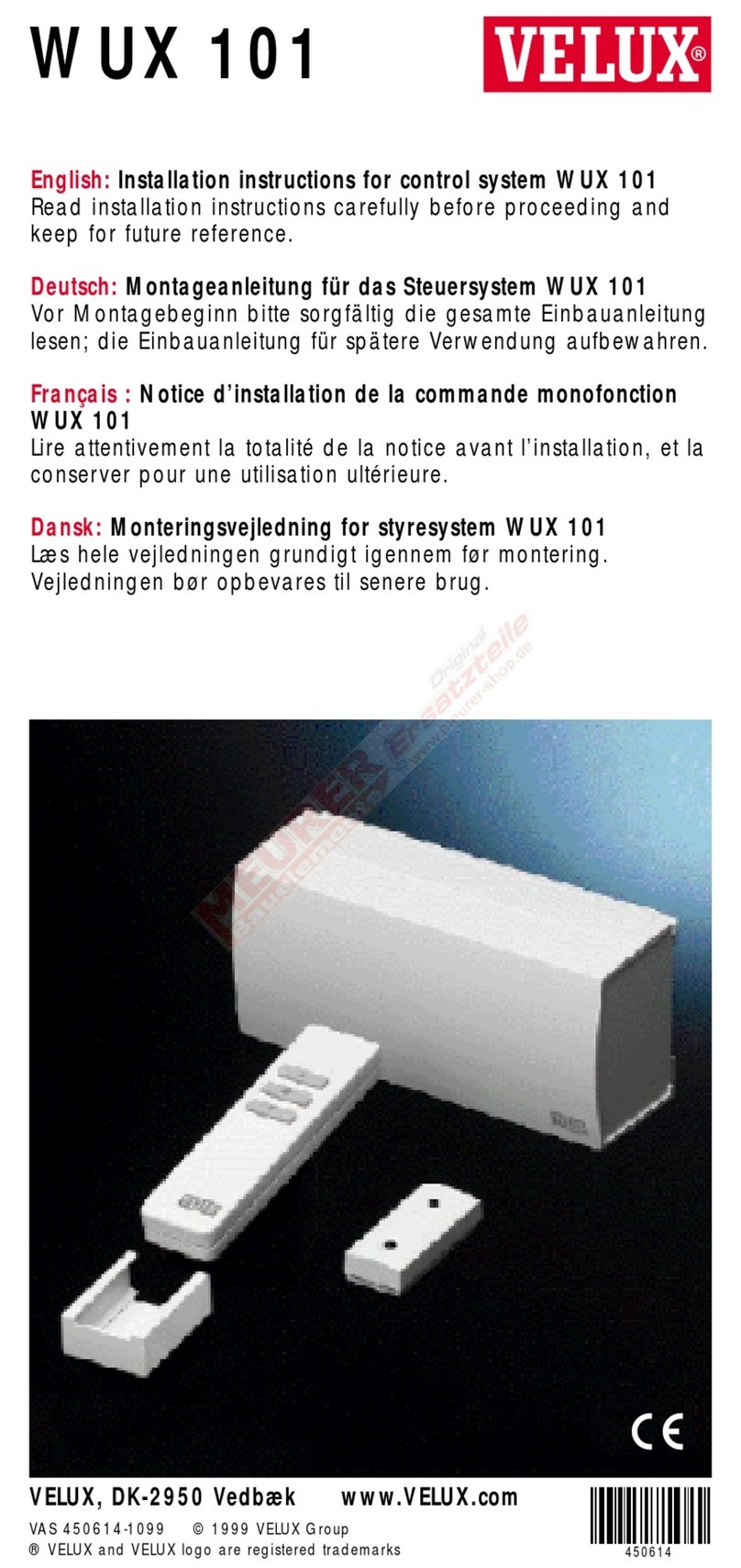
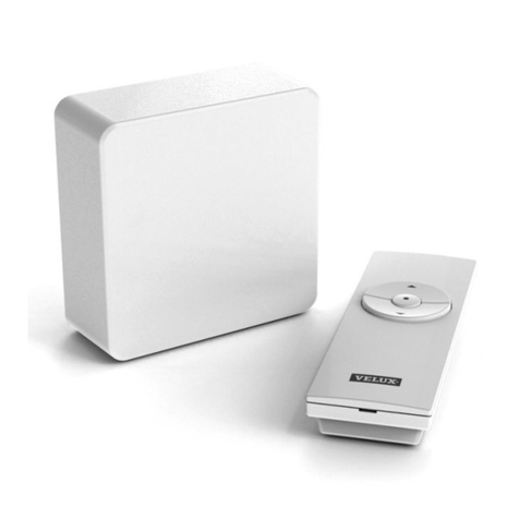
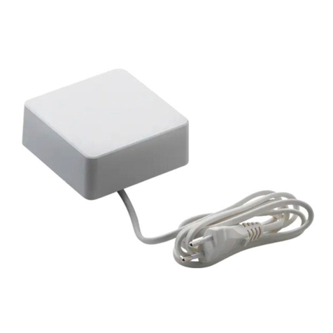
Velux Vario User manual

VAS 454764-2020-12
Vario by VELUX opening accessories
Control unit, wall switch, rain sensor and VELUX ACTIVE indoor climate control
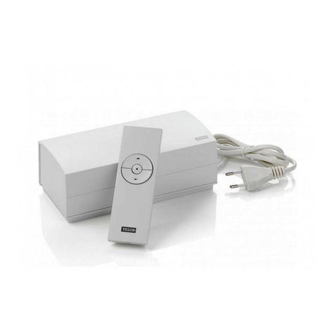
Control unit KLC 410
Wall switch KLI 311
(wireless control)
Rain sensor KLA 200
VELUX ACTIVE indoor climate control KIX 300
Bracket for rain sensor
Departure switch KLN 300 Indoor climate sensor KLA 300 Gateway 3LG
Contents of packaging
Add-on
Supplied by others
Extending wires for opening accessories
• Rain sensor wire: One 3 x 0.5 mm2UV cable (up to 30 metres)
• Actuator wire: One 2 x 1.5 mm2standard installation cable
(up to 20 metres)
VAS 454612-2020-01
RESET
Pressand hold
10sec
454612-2020-01_KLC410 label.indd 1 06-01-2020 08:54:14
Wires, not to be used for
Vario products

2 VELUX®
VAS 454612-2020-01
RESET
Press and hold
10 sec
454612-2020-01_KLC 410 label.indd 1 06-01-2020 08:54:14
Position control unit KLC410 on the wall inside the house (eg next to the consumer unit).
NOTE: When extending the cable (up to max. 20 m) between control unit KLC 410 and chain actuator
WMU/roller blind RMM, the cable dimensions in the table must be observed.
You can connect max one motor wire to one control unit KLC 410.
Control unit KLC 410 works for both single and dual actuated rooflights.
mm22 x 0.75 2 x 1.50
RMM 2 x RMM 4 x RMM
WMU 2 x WMU
KLC 410
RMM
WMU
20 m

VELUX®3
VELUX INTEGRA®
KLR 200
VELUX INTEGRA®
KLI 311 / KLI 312
max 10 min
1 sec
KLC 410
max 10 min
max 10 min
NOTE: Control unit KLC 410 must not be connected to mains supply until the installation of the chain
actuator and roller blinds is completed and they are ready for registration in the control. Once control unit
KLC 410 has been connected to the mains supply, registration of chain actuator/roller blind must take
place within 10 min. If the registration of the chain actuator/roller blind does not take place within 10 min,
disconnect the power from the control unit and then reconnect it.
AOperation with control A(control pad KLR 200): See instructions enclosed with control pad.
BOperation with control B(wall switch KLI 311/312): Connect the plug of KLC 410 to a power socket
and press the PAIR-button on the wall switch for 1 sec with a pointed object.
COperation with control C(potential-free switch): Connect the plug of KLC 410 to a power socket and
press the OPEN/UP or DOWN/CLOSE button.
If both a control and a potential-free switch are to be used for the operation of roller blinds, the roller
blind must be registered in control Aor B before connecting the potential-free switch.
If the roller blind is already registered in a control Aor B, the roller blind must be prepared for registra-
tion in the potential-free switch by means of the control unit. See instructions for control Aor B.
When the roller blind rolls up and down, it is ready for registration. Press OPEN/UP or CLOSE/DOWN
for 1 sec within 10 minutes.
CC
RMM
RESET
HVC
RAIN POWER
LINK
MOTOR
A
B
C

4 VELUX®
KLC 410
Connect rain sensor KLA 200 to control unit KLC 410.
NOTE: Make sure that the colours match as shown.
The cable for the rain sensor can be extended up to 30 m with a min 0.5 mm2cable.
CC
RMM
RESET
HVC RAIN POWER
LINK
MOTOR

VELUX®5
MAX
24 V
MAX
230 V AC
CC
RMM
RESET
HVC RAIN POWER
LINK
MOTOR
CC
RMM
RESET
HVC RAIN POWER
LINK
MOTOR
CC
RMM
RESET
HVC RAIN POWER
LINK
MOTOR
Control unit (connection plan)
1
RESET-button for registration of control or potential-free switch. After a long press (6-10 sec), regis-
tration in control must take place within 10 min.
IMPORTANT! After pairing with the remote control, connect the chain actuator with the top unit
using the locking pin. Now, calibrate the control unit by fully opening and closing the window using the
remote.
2
Potential-free entry for roller blinds
3
Potential-free entry for chain actuator
4
Entry for rain sensor KLA 200
5Plug connector for roller blinds
6
Plug connector for chain actuator
7230 V AC, consumption max 250 W
8
Jumper for compulsory chain actuator detection
Potential-free connection and function
Function of entries
OPEN/UP is controlled by connecting C and .
CLOSE/DOWN is controlled by connecting C and .
STOP is controlled by connecting C with both and .
Contact requirements
Potential-free contacts with a maximum resistance of 1 kΩ can be used. A current of 1 mA at 12 V DC
runs through the contact.
Contacts with a pulse signal can be used if the duration of the pulses is between 100 ms and 60 sec.
A contact with a pulse signal between 100 ms and 1 sec will make the product run to its end position.
A contact with a pulse signal between 1 and 60 sec will run the product until the contact is released.
Note: Do not activate the potential-free entries for more than 120 sec, as this could cause the products
to malfunction.
Do not connect voltage to the potential free entries.
Jumper
8A Auto detection of chain actuator
8B Compulsory detection of chain actuator
2
3
4
8
7
5
6
1
8A 8B

6 VELUX®
Important information
Read instructions carefully before installation and operation. Keep instructions for future reference and
hand them over to any new user.
Safety
•Control unit KLC 410, when connected to Vario by VELUX rooflight, can be used by persons (aged
8 years and above) with sufficient experience and knowledge if they have been given instruction con-
cerning safe use and understand the hazards involved. Cleaning and user maintenance must not be made
by unsupervised children.
•Children must not play with the rooflight or the control.
•It is recommended to place the control in the room where the product to be operated has been installed.
•Before operating, ensure that the rooflight is operated without risk of damage to property or injury to
people or animals.
•If repair or adjustment work is needed, disconnect mains supply and ensure that it cannot be recon-
nected unintentionally.
•For personal safety, never have your hand or body out of the rooflight without first having switched off
the mains supply to the system.
•The control unit must not be covered (maximum ambient temperature: 40 °C).
•The control unit must not be installed in rooms with a high level of humidity eg in rooms with swimming
pools.
Installation
• Note: Do not connect the control unit to the mains supply until the installation of the chain actuator and roller blinds is completed and
they are ready for registration in wall switch KLI 311/312, control pad KLR 200 or in a potential-free switch. See page 3.
• Do not connect the chain actuator to the mains supply during installation to prevent the rooflight from opening or closing suddenly and
uncontrollably.
• Maintenance and installation must be carried out in consideration of Health and Safety at Work requirements.
Product
• The control unit has been designed for use with chain actuators WMU 88V 2A or WMU 9093140 3A/6A in combination with Vario by
VELUX rooflight and VELUX roller blind RMM.
• The control unit can control one chain actuator WMU 88V 2A or WMU 9093140 3A/6A and up to four roller blinds RMM at a time.
• The control unit is compatible with products with the io-homecontrol®logo.
• The packaging must be disposed of in accordance with national regulations.
• The product, including batteries if any, is regarded as electrical and electronic equipment and contains hazardous materials, compo-
nents and substances. The crossed out wheeled bin symbolises that electrical and electronic equipment waste must not be disposed
of together with household waste. It must be collected separately at recycling stations or other collection sites or retrieved directly
from households to increase the possibilities of recycling, reuse and utilisation of electrical and electronic equipment waste. By sorting
electrical and electronic equipment waste with this symbol, you contribute to reducing the volume of incinerated or buried waste and to
reducing any negative impact on human health and the environment. Further information can be obtained from the local municipality's
technical administration or from your VELUX sales company.
• If batteries can be removed, product and batteries must be disposed of separately.
• In case of snow and/or ice, the operation of the rooflight may be blocked.
Maintenance and service
• Disconnect mains supply before carrying out any maintenance or service work on the rooflight and/or products connected to it and
ensure that it cannot be reconnected unintentionally.
• It is recommended to carry out at least one functional test annually to ensure that all moving parts of the rooflight and/or products con-
nected to it are fully functional and not influenced by wear or corrosion.
• If mains cable or any other cable is damaged, it must be replaced by qualified personnel in accordance with national regulations.
• It is recommended that VELUX service engineers carry out any repair work to the VELUX rooflight or VELUX electrical components.
• Spare parts are available through your VELUX sales company. Please provide information from the data label.
• If you have any technical questions, please contact your VELUX sales company, see telephone list or visit www.velux.com.
io-homecontrol
®
provides advanced and secure radio technology that is easy to install.
io-homecontrol
®
labelled products communicate with each other, improving comfort,
security and energy savings.
www.io-homecontrol.com
VELUX®7
Declaration of Conformity
We herewith declare that Vario by VELUX control unit KLC 410 (BI-SC004-01)
−is in conformity with the Low Voltage Directive 2014/35/EU, the EMC Directive 2014/30/EU,
the Radio Equipment Directive 2014/53/EU and the RoHS Directive 2011/65/EU,
−has been manufactured in accordance with the harmonised standards
EN 60335-1(2012),
EN 62233(2008),
EN 300220-2(2012),
EN 301489-1(2011),
EN 301489-3(2002),
EN 55014-1(2006)+A1(2009)+A2(2011),
EN 55014-2(1997)+A1(2001)+A2(2008) and
EN 55024(2010) and
−has been assessed in accordance with the harmonised standard EN 50581(2012).
When the above-mentioned control unit is connected to a VELUX INTEGRA®chain actuator
WMU 88V 2A or WMU 9093140 3A/6A or a VELUX INTEGRA®roller blind RMM installed in a Vario
by VELUX rooflight, the total system is to be considered as a machine, which is not to be put into ser-
vice until it has been installed according to instructions and requirements.
The total system then complies with the essential requirements of the Directives 2006/42/EC,
2014/35/EU, 2014/30/EU and 2014/53/EU of the European Parliament and Council.
VELUX A/S: . . . . . . . . . . . . . . . . . . . . . . . . . . . . . . . . . . . . . . . . . . . . . . . . . . . . . . . . .
(Jens Aksel Thomsen, Senior Certification Specialist)
Ådalsvej 99, DK-2970 Hørsholm. . . . . . . . . . . . . . . . . . . . . . . . . . . . . . . . . . . . . . . .
CE DoC 941986-02
03-02-2020

INSTALLATION INSTRUCTIONS FOR CONTROL UNIT KLC 410. ©2020 VELUX GROUP ®VELUX AND THE VELUX LOGO, VELUX INTEGRA, io-homecontrol AND THE io-homecontrol LOGO ARE REGISTERED TRADEMARKS USED UNDER LICENCE BY THE VELUX GROUP
VELUX Company Ltd.
Woodside Way
Glenrothes
Fife
Scotland
KY7 4ND
Telephone: +44 (0) 1592 778 246
Table of contents
Other Velux Control System manuals

Velux
Velux Integra Kux 110 User manual

Velux
Velux KFX 100 User manual

Velux
Velux WUX 101 User manual

Velux
Velux KLR 300 User manual

Velux
Velux KUX 100 User manual

Velux
Velux KFX 100 User manual

Velux
Velux KFX 210 User manual

Velux
Velux KUX 100 User manual

Velux
Velux Integra Kux 110 User manual

Velux
Velux KFX 110 User manual
Popular Control System manuals by other brands

Western Innovator
Western Innovator LC Series Installation and operating instructions

Invacare
Invacare LINX ACU user manual

ROTOTILT
ROTOTILT ICS Translation of the original instructions

Tyco
Tyco Raychem HWAT-ECO Installation and operation manual

Raven
Raven RCM Calibration and Operation Manual

2VV
2VV IC3-CONTROL Installation and operation manual