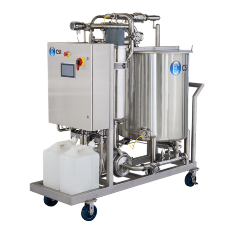
CSI CIP 2.0 Owner's manual

CIP 2.0
CONTROL SYSTEMS

2 |CIP 2.0 IOM
Safety ............................................................. 3
Important Safety Information .............................................3
Introduction........................................................ 4
About This Manual ......................................................4
Application ............................................................4
Technical Data .........................................................4
At A Glance (Equipment Overview) .................................... 5
Safety ............................................................. 6
Built-In Safety ..........................................................6
Air Lockout Capability ...................................................6
E-Stop Capability .......................................................6
Installation..........................................................7
Air Connections ........................................................7
Operation.......................................................... 8
Opearation Screens.....................................................9
Trend Screen..........................................................14
Equipment Screen .....................................................16
Alarms Screen ........................................................17
History Screen ........................................................18
Configuration Screens ...............................................19
Diags Screen ......................................................22
Phase Screen ..................................................... 23
Tuning Screen .....................................................24
Maintenance ......................................................25
Checklist .............................................................25
Replacing “Poly” Tubing ................................................25
Replacing Pressure Regulator Filter Element ..............................26
Replacing Solenoid Valve ...............................................26
Troubleshooting ................................................... 27
Warranty .........................................................28
TABLE OF
CONTENTS

CIP 2.0 IOM | 3
The CIP 2.0 Manual includes essential information for installing, operating, and
maintaining equipment properly and in a safe manner. Failure to do so could
result in personal injury and/or equipment damage.
DO NOT attempt to remove and/or modify CIP 2.0 products or programming.
Doing so can create unsafe conditions for operator(s) and surrounding persons.
Changes to CIP 2.0 products or programming void all warranties.
DO NOT place any CIP 2.0 product in an application where general product
service ratings are exceeded. Doing so puts operator(s) and surrounding
persons at risk of personal injury and may result in equipment damage.
THE MEANING OF DANGER, WARNING, AND CAUTION IN THESE INSTRUCTIONS
Danger: Indicates an imminently hazardous situation which, if not avoided, has a
high likelihood of resulting in death or serious injury. The word Danger indicates
the most extreme cases of risk that warrant immediate attention.
Warning: Indicates a potentially hazardous situation which, if not avoided, could
result in death or serious injury. The word Warning is used for moderately at-risk
cases that warrant immediate attention.
Caution: Indicates a potentially hazardous situation which, if not avoided,
may result in minor or moderate injury. “Caution” may also indicate an unsafe
operating or maintenance practice.
If at any point during operation, a Danger, Warning, or Caution indication is
present, the operator should immediately take steps to resolve the problem and
notify a supervisor.
Do not remove labeling on any CIP 2.0 product. Immediate replacement of
missing labels is important to the safety of all users.
IMPORTANT
SAFETY
INFORMATION

4 |CIP 2.0 IOM
INTRODUCTION Thank you for purchasing a CIP 2.0 Product!
This manual contains operation instructions for the CIP 2.0 Control System.
ABOUT THIS MANUAL
This manual covers the complete line of CIP 2.0 systems. All CIP 2.0 systems are
available with optional equipment that can provide additional functionality.
Please contact CSI at 800.721.2394 or 417.831.1411 for assistance.
APPLICATION
CSI’s CIP 2.0 regulates the operation of your Clean-in-Place system. CIP 2.0
takes the guesswork out of configuring and controlling the start, stop, flow, tem-
perature, and chemical concentrations required for a successful clean in place
cycle. If used properly, your CIP 2.0 system can be a source of savings and a
vital step in ensuring product quality through rapid and eective cleaning.
TECHNICAL DATA
• Compressed air pressure: 90–100 psig (requires at least 90, no more than 100)
• Air inlet size: 1/2” FNPT
• Maximum product pressure: 145 psig
• Product Temperature range: 0°F–185°F
• Electrical Requirement: AC 480V, 60Hz +/- 6%
• Amperage requirement based on system configuration

CIP 2.0 IOM | 5
AT A GLANCE 2
1
68
Emergency Stop (E-Stop)
Touchscreen
Power Disconnect Switch
Pressure Gauge
Pressure Regulator
Control Panel
Chemical Pumps
Chemical Tanks
Tank Level Transmitter
2
3
4
5
6
7
8
9
3
79
4
5

6 |CIP 2.0 IOM
SAFETY The CSI CIP 2.0 control package includes built-in safety features including air
lockout and emergency stop capabilities. The control units can also incorporate
system timeouts for added operator safety.
E-STOP CAPABILITY
Activate E-Stop to turn o all operations.
To release the E-Stop, twist clockwise until it pops up.
AIR LOCKOUT CAPABILITY
The photo on the left shows the air control in the Supply (SUP) position. To
prevent accidental operation, turn the air control to the OFF position and lock it
with a padlock (OSHA lockout/tagout standard for control of hazardous energy).

CIP 2.0 IOM | 7
WARNING
INSTALLATION The CIP 2.0 control cabinet arrives mounted to the skid and pre-wired to in-
struments installed on the skid. Typical installation requires a dedicated 480V
3-Phase with Branch Circuit Protection with enough amperage for the configu-
ration. Electrical schematics provided with the control panel indicate location,
voltage, and amperage requirement for the panel.
To avoid electrocution, ALL electrical work should be done by a registered elec-
trician, following industrial safety standards and local codes. All power must be
OFF and safely locked out during installation.
The CIP 2.0 system is designed to work as a standalone system or configured
to connect to the plant network via Ethernet for permissions, data logging, and
E-Stop connectivity. If the system is intended to communicate with the plant net-
work, an Ethernet drop must be provided to the CIP 2.0 control system and the
system uses 4-5 unique IP addresses depending on configuration.
DISCLAIMER OF LIABILITY
CSI does not assume responsibility and expressly disclaims liability for loss,
damage, or expenses that arise in any way from the installation, operation, use,
or maintenance performed in accordance with this manual. CSI assumes no
responsibility for any infringement of patents or other rights of third parties that
may result from use of the module. No license is granted by implication or other-
wise under any patent or patent rights.
CSI reserves the right to make changes to the product, specifications, or this
manual without prior notice.
Note: CSI recommends that the cabinet be supplied with clean process air at
the minimum pressure and flow rate for your application.
AIR CONNECTIONS
Note: CSI recommends that the control cabinet be supplied with clean instru-
ment air at the minimum pressure and flow rate for your application.
AIR INPUT TO CABINET
Air connection 1/2” NPT Female

8 |CIP 2.0 IOM
OPERATION CONTROL PANEL
Use the touchscreen control panel to select wash parameters and cleaning
cycle. Operators should take a moment to familiarize themselves with the items
in bold below.
SYSTEM START
1. Verify all Swing Connections and piping connection.
2. Verify the Air Relief Switch is in the On position.
3. Verify the E-Stop is not activated.
4. If not already completed, log on to the system by pressing the Logon/Logo
button.
5. Input your username and password
Default User Name: Operator
Default Password: operator
6. To initiate a wash cycle, press the Commands button.
7. If the system has more than one supply, select the appropriate Supply Header.
A prompt asks you to select a circuit.
8. Select the appropriate circuit. The system also indicates the last wash type
and time stamp for each circuit.
9. If your system uses swing connections, it prompts you to verify that those
connections have been made.
10. If your system requires plant permission, the system requests permission and
holds until permission is granted.
11. Select the appropriate wash type to start the system. The process can be
Aborted at any time from this screen.
12. Once the wash has started, press Close Window.
13. The system runs the wash cycle in automatic mode until the circuit set-points
have been completed, an error occurs, or and E-Stop condition occurs.

CIP 2.0 IOM | 9
OPERATION
SCREENS:
MAIN SCREEN
The main screen displays the equipment located on the skid, including tanks,
valves, pumps, heat exchangers, and piping.
CIP 2.0 is a versatile program oering full programming capabilities for an
assortment of systems ranging from small single-tank, single-supply systems to
the four-tank, dual supply system (as shown above).
Dual supply means you can clean two independent processes simultaneously as
there are two separate supply pumps, each having independent chemical dosing
and heat exchange equipment.
Dual supply systems provide reduced cost and space requirements when
compared to operating two separate clean in place systems.
Log in to start a wash or view screens. To log in, select the Logon/Logo
button on the far right, and select LogOn.
The Default Login is as follows:
User Name: Operator
Password: operator
2
3
2
4
5
3
4
5

10 |CIP 2.0 IOM
START THE WASH CYCLE
Select the Commands button.
If your system has more than one supply header, select the appropriate
header based on your piping configurations.
OPERATION
SCREENS
2
2

CIP 2.0 IOM | 11
OPERATION
SCREENS
If your A prompt screen appears: Select A Circuit or Quit without Starting.
Press Select A Circuit to continue the starting process. The screen prompts
you to select the desired circuit or Cancel.
Select the desired circuit number.
2
2
3
3

12 |CIP 2.0 IOM
OPERATION
SCREENS
If the system is configured with swing connections, they must first be verified.
If the connections are in place press Swing Connections Complete.
If the system is configured to request permission from a plant PLC before
beginning operation, it does so now.
If the system stalls at this point, it may be waiting to receive facility permission
from the plant PLC, or it might not be getting the signal from the plant PLC entirely.
1
2
2

CIP 2.0 IOM | 13
OPERATION
SCREENS
Once permission is granted, the operator is presented with available wash types.
From this screen the operator can: Start, Hold, Restart, & Abort a wash.
Select Start on the desired wash type. Then press Close Window.
The system should now run the selected wash in automatic mode until the wash
set-points have been met or there is an error or E-stop command.
Once completed, the system automatically returns to an idle state.

14 |CIP 2.0 IOM
The trend screen displays process parameters over the course of the cycle.
To display parameters, press Trend from the main navigation window.
The trend screen maps the analog values associated with your system.
All CIP 2.0 programs include: Conductivity, Temperature, and Supply
Flow trends as seen above.
More complicated systems, such as a dual supply system, display two trends
for Conductivity, Temperature, and Supply Flow, each referencing their
corresponding system.
Additional process parameters can be recorded and observed on an individual
skid basis.
TREND SCREEN
2
3A
3B
4
2 3 4

CIP 2.0 IOM | 15
OPERATION
SCREENS:
EQUIPMENT
To display the status or manually command a piece of equipment, select
Equipment from the main navigation. The screen displays the equipment
available with the system.
Press Clean HMI Screen to display a popup window which hides the CIP
skid objects. This allows the 4X Rated HMI screen to be wiped down with a
damp microfiber cloth — without unintentionally clicking on skid objects.
The Close button takes you back to the Main HMI screen.
2
3
2
3

16 |CIP 2.0 IOM
OPERATION
SCREENS:
EQUIPMENT
Press Equipment in the navigation bar.
Select Maintenance Info to display a list of the available PDFs and videos for
pumps, valves and instruments on your system — which provides easy access to
operators and maintenance personnel.
Press any PDF or Video button to view information on screen for a piece of
equipment.
2
3
2
3

CIP 2.0 IOM | 17
The Alarms button in the main navigation blinks red to indicate a situation
that should be investigated immediately. To see the cause of the alarm(s) select
Alarms from the main navigation.
The Alarms button blinks until the alarm(s) are acknowledged.
To acknowledge alarm(s), highlight the alarm by clicking it, then press the
check mark at the upper-left corner. Once acknowledged, the alarm occurrence
is recorded in the event log — as shown on page 18.
OPERATION
SCREENS:
ALARMS
2A
2B
2

18 |CIP 2.0 IOM
To access the event log, press the History button from the main navigation.
Then press Events from the drop-down menu.
OPERATION
SCREENS:
HISTORY

CIP 2.0 IOM | 19
CONFIGURATION
SCREENS
To change the system set points from the factory settings, log in at an elevated
level such as engineer. (Username: engineer; Password: engineer)
Press the Config button from the main navigation menu. Then press Main
from the drop-down menu to get to the main configuration screen.
From here you can change the set points for temperature and conductivity and
for wash types.
After changing the set points, the tanks should cycle on and o between their
respective percentage values to maintain fluid level.
To change flow rates and times for a selected circuit, press Circuit Config.
2
2

20 |CIP 2.0 IOM
CONFIGURATION
SCREENS
On the circuit settings page the number of circuits available can be configured
based on your piping configuration, up to 15 total circuits per supply.
Select whether the circuit needs to verify swing connection (Has Swing Conn)
or needs to wait for facility permission (Wait For Facility Perm) before starting
Input the flow rate set-point for the circuit
Input the required time at the specified flow rate temperature and conductivity
before advancing to the next phase
Pulse Rinsing is only visible on this screen if the VFD drop percentage is
greater than 0 on the Skid Initial Setup screen (see page 21). If there is no pulse
amount set, then it is disabled by default.
2
2 3 4
3
4
5
5
Table of contents
Other CSI Control System manuals