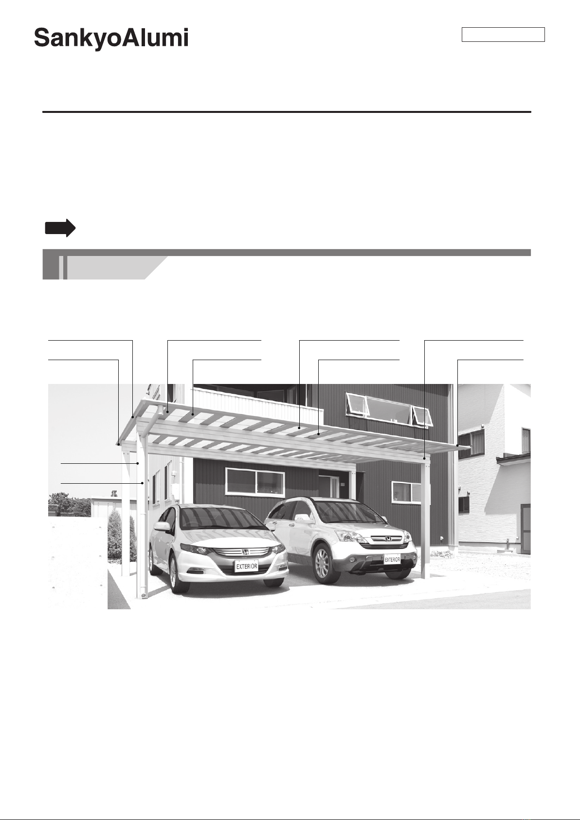
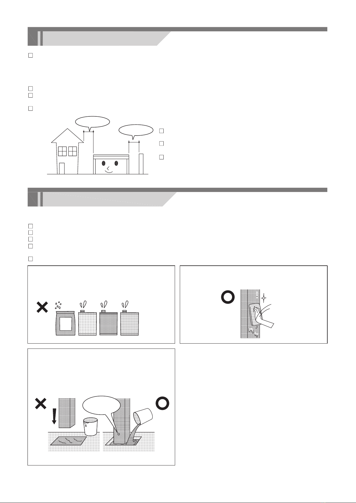
manuals.online logo
Brands
  1. Home
  2. •
  3. Brands
  4. •
  5. Sankyo
  6. •
  7. Tent
  8. •
  9. Sankyo CSS Series Programming manual

Sankyo CSS Series Programming manual

Assemblingmanual
carport
CSS-series
Thank you very much for choosing our company's products.
Please be sure to thoroughly read these instructions for assembly in order to properly and
smoothly assemble or attach this product.
Construction shall be implemented by professionals. Problems may occur if the product is
installed by someone without the proper knowledge.
Please be sure to return the instruction manual in its original package to the owner after
explaining product operation procedures,maintenance and inspection methods.
side frame roof panel
round gutter
beam
rafter
post
gutter
Name of part
Notice
1
HZ1750C-E
rear frame roof retainer
support rafter
enough space
enough spacePositioning the posts so that they do not affect underground
objects (water supply, drain pipes, etc.).
When moving the posts, please follow the company
specifications.
Install it so that the exhaust of hot-water supply, heating
and/or the car do not hit directly to the products and do not
retain around products. There is a possibility that the
surface abnormality occurs as the coating film stripping.
Precautions during installation
Precautions during construction
The carport is a simple garage. Do not change or remodel it for storage, recreational or residential
purposes.
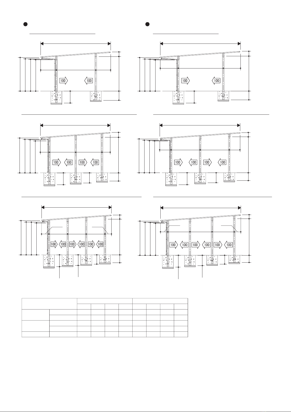
This product is for snow areas. It has a snow accumulation strength of 1500N/m2 (153.0kg/m2), 3000N/m2
(306.1kg/m2), 4500N/m2 (459.2kg/m2) which corresponds to 50cm,100cm,150cm of snowfall. (specific
weight 0.3)
Do not install it in the place where snow slides down from the building roof directly.
When installing it besides concrete wall, etc., keep the enough clearance between the post and the wall
due to not clash each other during strong wind.
Do not install it in the place where the strong wind blow up the roof.
The precautions provided herein contain important information to ensure product performance, function,
strength and safety. Please be sure to follow them during construction.
Follow the instructions and be sure that all the specified screws and bolts for assembly are tightened securely.
Do not use anything other than the specified parts or optional parts.
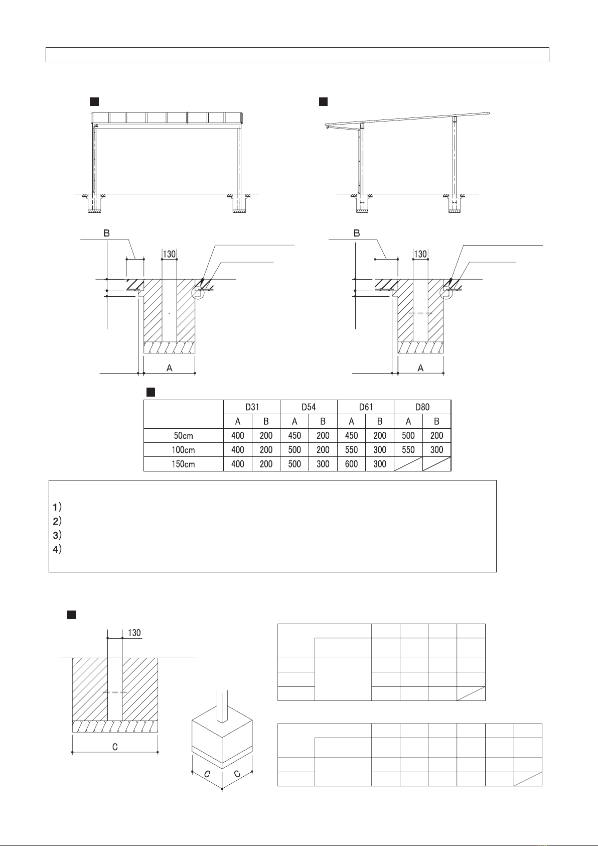
The foundation should comply with or exceed dimension specifications.
Allow sufficient curing time for the concrete (4 to 7 days) and do not place heavy objects on it or subject it to
vibrations during the curing period.
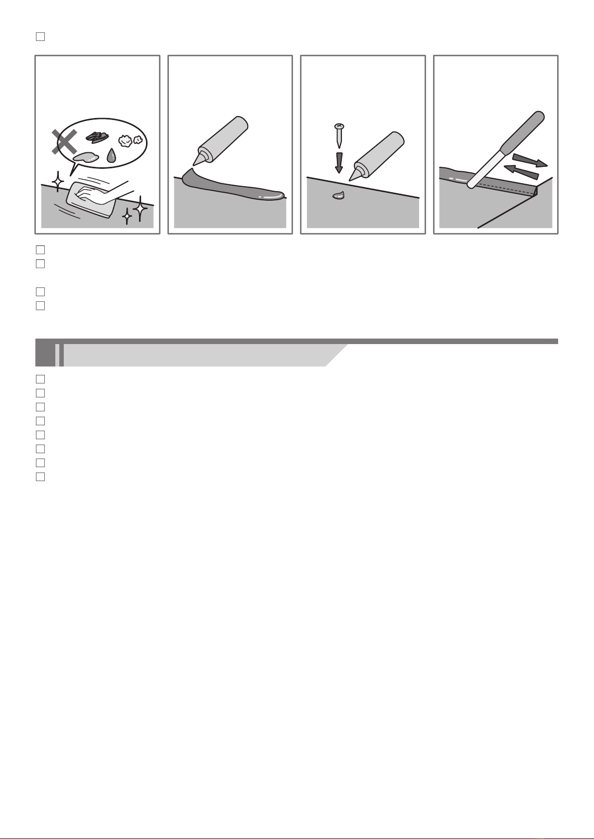
Be sure to keep the note below to prevent aluminum materials corrode.
Do not use sea sand for the foundation since it
contains salt and may cause corrosion.
Do not use a cement enhancer, water-reducing
agent or cryoprotectant. They may cause the
posts to corrode.
Immediately wipe off any mortar or stains from
the surface of aluminum parts since they may
cause corrosion.
Be sure to provide gravel for the foundation to
allow drainage, insert water drainage holes (φ5)
at the base of the posts and foundation. Failure
to do so may lead to water accumulation inside
the posts and damage them if the water freezes
and expands inside.
sea
sand
cement
enhancer
water-
reducing
cryopro
tectant
water drainage
hole
(1)
(3)
(2)
2
3
Be sure to put the sealant glue as the following.
When the G.L (Ground line) is steep, be sure to keep the depth of the post at the lowest level.
After construction, check the products to see if the bolts, screws, nuts, etc. loosen or any dangerous places
exist.
Be sure to check if the product has scratches, dents or dint.
Be sure to explain product operation procedures, maintenance and inspection methods to the owner.
Electric drill, Drill
Ratchet wrench, Adjustable end wrench
Electric screwdriver
Measure, Level, Plumb bob, Cutter, Pillar, Plastic hammer
Foundation materials (Cement, Aggregate, etc.)
Sealant, Caulk gun, Pallet
Cropper or Saw
Please prepare tools and materials as needed.
Wipe off any stains
from the sealing part.
Be sure to apply a
sealant, as specified.
After putting the
sealant glue on the
hole made in its all
wall body, fully tighten
the screw.
Seal completely deep
enough and finish the
surface with a pallet.
sealing
sealing
rust dust
oil water
Necessary Tools and Materials For Installation
(1)(2) (3)(4)
4
Dimension, position of posts and base dimension
Dimension, position of post
19size
31size
25size
Length dimension (W), height dimension (H) and post standard position (post could be changed as the dimension of ← →)
Standard type (Height size[ ] indicates H25 size, [[ ]] indicates H27 size.)
Be sure to keep the base depth more than ( ) dimension.
In case of using “clearance cover (option)”, be sure to make 100mm clearance between carport frame and house wall.
※1
※2
2438D31,D34,D42
D54,D61
A
2482
2544
2438
2482
snowfall 100cm
snowfall 150cm
D80
D31,D34
D42,D54,D61
2325
B
2368
2430
2325
2368
2332
C
2376
2438
2332
2376
233
D
277
339
233
277
W19
・The above table indicates H23 size. In case of H25, add 200mm to A〜C dimension, for H27, add 400mm.
Standard type(W19〜W31)
2426
A
2469
2531
2426
2469
2312
B
2356
2418
2312
2356
2288
C
2332
2394
2288
2332
246
D
289
351
246
289
W25
2410
A
2453
2515
2410
2453
2296
B
2340
2402
2296
2340
2231
C
2275
2337
2231
2275
262
D
305
367
262
305
W31
G.L G.L
G.L
1300352.5
287.5
H=2300 [2500] [[2700]]
GL to gutter bottom face: A
H1=2391 [2591] [[2791]]
766
W=1940
D
GL to elbow bottom face: C
※2
(100)
GL to drain elbow bottom face: B
  857  
※1(766)
1500
467.5
H1=2405 [2605] [[2805]]
752
W=2500
D
※2
(100)
532.5
  857  
※1(752)
GL to elbow bottom face: C
H=2300 [2500] [[2700]]
GL to drain elbow bottom face: B
GL to gutter bottom face: A
762.5
697.5
GL to elbow bottom face: C
H=2300 [2500] [[2700]]
GL to drain elbow bottom face: B
GL to gutter bottom face: A
W=3060
D
H1=2412 [2612] [[2812]]
745
1600
  857  
※1(745)
※2
(100)
5
51size58size
Snowfall 50cm depth 31/54/61
Snowfall 50cm depth 80, snowfall 100cm depth 31/54/61 Snowfall 50cm depth 80, snowfall 100cm depth 31/54/61
Snowfall 100cm depth 80, snowfall 150cm depth 31/54/61 Snowfall 100cm depth 80, snowfall 150cm depth 31/54/61
Snowfall 50cm depth 31/54/61
snowfall 50cm
2427D31,D54,D61
D80
A
2523
2461
2531
2469
snowfall 100cm
snowfall 150cm
D31,D54,D61
D80
D31,D54,D61
2326
B
2421
2359
2430
2368
2271
C
2409
2347
2429
2367
331
D
360
298
351
289
W51
2415
A
2510
2448
2531
2469
2314
B
2409
2347
2430
2368
2244
C
2382
2320
2429
2367
343
D
372
310
351
289
W58
※The above table indicates H23 size. In case of H25, add 200mm to A〜C dimension.
Standard type(W51〜W58)
G.L
G.L
G.L
G.L
G.L
G.L
659 1900 1900 593
1350 1350 1350
533.5 468.5
1308.5 3250
833.5 2100 2100 768.5
1600 1600 1600
533.5 468.5
H1=2527 [2727]
1243.5
W=5802
H1=2566 [2766]
H1=2583 [2783]
H1=2594 [2794]
W=5802
W=5802
W=5052
W=5052
H1=2636 [2836] 630
724
591
710
563
763
※(668)
668
574
745
※(633)
633
521
H=2300 [2500]
GL to elbow bottom face: C
GL to drain elbow bottom face: B
GL to gutter bottom face: A
GL to elbow bottom face: C
H=2300 [2500]
GL to gutter bottom face: A
H=2300 [2500]
GL to elbow bottom face: C
GL to drain elbow bottom face: B
GL to gutter bottom face: A
H=2300 [2500]
GL to gutter bottom face: A
H=2300 [2500]
857  
※(668)
W=5052
28501133.5 1068.5
H1=2499 [2699]658
GL to gutter bottom face: A
GL to drain elbow bottom face: B
GL to elbow bottom face: C
H=2300 [2500]
857  
※(724)857  
※(658)
857  
※(630)
857  
※(633)
857  
※(710)
GL to elbow bottom face: C
GL to drain elbow bottom face: B
GL to gutter bottom face: A
GL to elbow bottom face: C
GL to drain elbow bottom face: B
D
D
D
D
D
D
6
Dimension, position of posts and base dimension
Dimension, position of post
51size58size
Length dimension (W), height dimension (H) and post standard position (post could be changed as the dimension of← →)
Deluxe type (〔H=25〕indicates H25.)
The post depth of embedment is more than ( ) dimension.
Snowfall 50cm depth 31/54/61
Snowfall 50cm depth 80, snowfall 100cm depth 31/54/61 Snowfall 50cm depth 80, snowfall 100cm depth 31/54/61
Snowfall 100cm depth 80, snowfall 150cm depth 31/54/61 Snowfall 100cm depth 80, snowfall 150cm depth 31/54/61
Snowfall 50cm depth 31/54/61
※
snowfall 50cm
2353D31,D54,D61
D80
A
2448
2386
2457
2395
snowfall 100cm
snowfall 150cm
D31,D54,D61
D80
D31,D54,D61
2326
B
2421
2359
2430
2368
2271
C
2409
2347
2429
2367
331
D
360
298
351
289
W51
2341
A
2436
2374
2457
2395
2314
B
2409
2347
2430
2368
2244
C
2382
2320
2429
2367
343
D
372
310
351
289
W58
※The above table indicates H23 size. In case of H25, add 200mm to A〜C dimension.
Deluxe type
G.L G.L
G.L
G.L
G.L
G.L
W=5075
28501147 1078
673 1900 1900 602
1350 1350 1350547 478
1322 3250
847 2100 2100 778
1600 1600 1600
547 478
H1=2499 [2699]
H1=2527 [2727]
1253
W=5825
H1=2566 [2766]
H1=2594 [2794]
W=5825
W=5825
W=5075
W=5075
H1=2636 [2836]
658
630
724
591
710
563
H1=2583 [2783]
763
※(668)
668
574
745
※(633)
633
521
GL to gutter bottom face: A
GL to drain elbow bottom face: B
GL to elbow bottom face: C
H=2300 [2500]
H=2300 [2500]
GL to drain elbow bottom face: B
GL to gutter bottom face: A
GL to elbow bottom face: C
GL to drain elbow bottom face: B
GL to gutter bottom face: A
H=2300 [2500]
H=2300 [2500]
GL to gutter bottom face: A
GL to drain elbow bottom face: B
GL to elbow bottom face: C
H=2300 [2500]
GL to elbow bottom face: C
GL to drain elbow bottom face: B
GL to gutter bottom face: A
H=2300 [2500]
GL to elbow bottom face: C
GL to drain elbow bottom face: B
GL to gutter bottom face: A
857  
※(668)
857  
※(633)
857  
※(724)
857  
※(658)
857  
※(630)
857  
※(710)
D
D
D
D
D
D
7
Dimension, position of posts and base dimension
Dimension, position of post
31size34size42size
61size
80size
post center : 2811
post center : 5093
Standard : D=3050
Deluxe : D=3089
post center : 5811
Standard : D=6050
Deluxe : D=6089
post center : 7759
beam joint part 1970
Standard : D=7998
Deluxe : D=8037
Standard : D=5332
Deluxe : D=5371
54size
Depth dimension (D)
(Length dimension W19・25・31 size only)(Length dimension W19・25・31 size only)
Standard : D=3434 Standard : D=4152
718590 718 718 590 718590 718 718 718 590
post center : 3195post center : 3913
8
Base size
1.In case of concrete floor
Depth direction
In case of 100kN/m2endurance strength of ground
Length direction
Depth・Length direction
The projections which
prevent floating
Type
The projections which
prevent floating
steel rod
steel rod
more than 50 more than 100
more than 50 more than 50
Thickness of concrete floor is more than 100mm.
Steel rod and welding wire net are arranged in concrete floor.
Dimension of projection which prevents floating at 4 rounds is more than 50mm×50mm.
Distance(B)from outside edge of base to around concrete floor is more than dimension
specifications.
In case of base size for concrete floor, please install under below condition.
2.In case of no concrente floor or no correspond to above condition.
50cm
100kN/㎡
500
D31
endurance
strength of ground
endurance
strength of ground
CC
500
500
500
500
600
550
CC
550
650
550
600100cm
150cm
Type
D54 D61 D80
◎Length 51size・58size
100cm 100kN/㎡400
D31
CC
400
400
400
400
CC
400
400
450150cm
Type
D34 D42 D54
◎Length 19size・25size・31size
C
400
500
450
C
D61 D80
9
Please open the captioned carton and check all contents in advance.
Please check the parts defective or any damage.
We packed some extra screw in the parts box. (x) number is necessary Q'ty for installation.
Parts contents
content
description shape quantity
Parts ID content
description shape quantity
Parts ID
post set
depth 61
and under
post set
depth 80
post
post
beam
beam set
beam set
beam set
beam joint
parts set
beam set
anchor rod
anchor rod
post connecting part
support plate
bolt rail
bolt rail
hexagon bolt
hexagon bolt
hexagon nut
plain washer
10
spring washer
10
hexagon bolt
hexagon bolt
cap nut
drilling screw
plain washer
10
spring washer
10
hexagon bolt
hexagon bolt
hexagon nut
plain washer
10
spring washer
10
beam cap C
beam cap A
beam cap B
beam
beam
beam joint
sleeve
beam joint plate
beam joint cover
bolt rail
tapping screw
tapping screw
truss
hole seal
tapping screw
tapping screw
truss
hole seal
Right Left
each1pc
CSSH-M23A
CSSH-L23A
CSSH-LL23A
CSSH-M23B
CSSH-L23B
CSSH-LL23B
CSSH-M25A
CSSH-L25A
CSSH-LL25A
CSSH-M25B
CSSH-L25B
CSSH-LL25B
CSSH-L27B
CSSH-LL27B
CSSH-MW23B
CSSH-LW23B
CSSH-MW25B
CSSH-LW25B
CSSH-LW27B
CSST-31A
CSST-54A
CSST-54B
CSST-61B
CSST-42A
CSST-M31
CSST-M34
CSST-M42
CSST-31A
CSST-54A
CSST-54B
CSST-61B
CSST-31A・M31・M34
22(20)
CSST-42A・M42
24(26)
CSST-54A・54B
34(32)
CSST-42A
CSST-M31
CSST-M34
CSST-M42
CSST-61B
38(36)
CSST-31A・M31・M34
22(20)
CSST-42A・M42
24(26)
CSST-54A・54B
34(32)
CSST-61B
38(36)
GB8117
2
CSST-□□A
CSST-□□B
CSST-M□□
content
description shape quantity
Parts ID content
description quantity
Parts ID
depth set
[standard]
depth set
[deluxe]
depth set
[deluxe]
depth set
[standard]
gutter
(for standard)
rear frame
(for standard)
panel holder
(L=1197)
(L=1767)
(L=1325)
(L=2869)
(L=2174)
(L=2869)
(L=2174)
(L=2023)
(L=1197)
(L=1767)
(L=1456)
(L=1895)
gutter
(for standard)
rear frame
(for standard)
gutter connecting parts A
(for standard)
gutter connecting
parts B
panel holder
panel holder
panel holder
panel holder
panel holder
(L=2043)
panel holder
(L=1456)
panel holder
(L=1895)
panel holder
(L=2174)
panel holder
(L=2869)
panel holder
gutter
(for deluxe)
rear frame
(for deluxe)
panel holder
panel holder
panel holder
panel holder
(L=2174)
panel holder
(L=2869)
panel holder
gutter
(for deluxe)
rear frame
(for deluxe)
gutter connecting parts A
(for deluxe)
gutter connecting
parts B
panel holder
panel holder
Right Left
each1pc
Right Left
each1pc
Right Left
each1pc
Right Left
each1pc
10
CSSM-31N
CSSM-34
CSSM-42
CSSM-80N
CSSMD-31N
CSSMD-54N
CSSMD-61N
CSSMD-80N
CSSM-31N
1
CSSMD-31N
1
CSSMD-31N
1
CSSMD-54N
CSSMD-80N
1
2
1
2
1
1
1
1
1
2
1
2
CSSM-31N
CSSM-34
CSSM-54N
CSSM-54N
CSSM-61N
CSSM-80N
CSSM-61N
CSSM-80N
CSSM-34
CSSM-42
CSSM-42
CSSMD-54N
CSSMD-61N
CSSM-54N
CSSM-61N
CSSMD-61N
CSSMD-80N
content
description shape quantity
Parts ID content
description shape
Parts ID
round gutter
set
G1CAH
side frame set
[standard]
parts set
[standard]
round gutter
side frame
(for standard)
side frame
(for deluxe)
roof retainer
(end)
roof retainer
(end)
roof retainer
(middle)
support
rafter
rafter
side frame set
[deluxe]
rafter set
support
rafter set
rear frame cap
connecting parts
glue
label
snow label
name label
caution label
assembling manual
instruction manual
gutter cap
quantity
11
GB2898
saddle
GB3887
drain elbow
GB2752
elbow
GB8208
gasket
GB2739
drain
Right Left
each1pc
Right Left
each1pc
CSSE-51-4
CSSE-58-4
CSSE-51-6
CSSE-58-6
CSSE-51-8
CSSE-58-8
CSSED-51-4
CSSED-58-4
CSSED-51-6
CSSED-58-6
CSSED-51-8
CSSED-58-8
CSST-W51A4-3
CSST-W58B4-3
CSST-W51A4-4
CSST-W58B4-4
CSST-W51A6-3
CSST-W58B6-3
CSST-W51A6-4
CSST-W58B6-4
CSST-W51A8-3
CSST-W58B8-3
CSST-W51A8-4
CSST-W58B8-4
CSSHT-W51A4-2
CSSHT-W58B4-2
CSSHT-W51A4-3
CSSHT-W58B4-3
CSSHT-W51A4-4
CSSHT-W58B4-4
CSSHT-W51A6-2
CSSHT-W58B6-2
CSSHT-W51A6-3
CSSHT-W58B6-3
CSSHT-W51A6-4
CSSHT-W58B6-4
CSSHT-W51A8-2
CSSHT-W58B8-2
CSSHT-W51A8-3
CSSHT-W58B8-3
CSSHT-W51A8-4
CSSHT-W58B8-4
3
CSST-
W□□□□-3
4
CSST-
W□□□□-4
3
CSST-
W□□□□-3
4
CSST-
W□□□□-4
2
CSSHT-
W□□□□-2
CSSB-5180N
1
1
1
2
1
2
3
6
2
4
1
CSSB-5880N
CSSE-19
CSSE-25
CSSE-31
CSST-W19A-3
CSST-W25A-3
CSST-W31A-3
CSST-W19A-4
CSST-W25A-4
CSST-W31A-4
CSST-W19A-5
CSST-W25A-5
CSST-W31A-5
CSSHT-W19A-5
CSSHT-W25A-5
CSSHT-W31A-5
CSSHT-W19A-4
CSSHT-W25A-4
CSSHT-W31A-4
CSSHT-W19A-3
CSSHT-W25A-3
CSSHT-W31A-3
5
CSST-
W□□□□-5
5
CSST-
W□□□□-5
3
CSSHT-
W□□□□-3
4
CSSHT-
W□□□□-4
5
CSSHT-
W□□□□-5
HZ1750
screws
See screws guantities
table on page12.
CSSB-□□
31N・34・42
54N・61N
CSSB-□□80N
CSSB-□□80N
CSSB-□□80N
CSSB-□□80N
CSSB-□□
31N・34・42
54N・61N
CSSB-□□
31N・34・42
54N・61N
CSSB-□□
31N・34・42
54N・61N
CSSB-□□
31N・34・42
54N・61N
CSSB-5131N
CSSB-5831N
CSSB-5154N
CSSB-5854N
CSSB-5161N
CSSB-5861N
CSSB-5180N
CSSB-5880N
CSSB-1934
CSSB-1942
CSSB-1954
CSSB-1961
CSSB-1980
CSSB-2534
CSSB-2542
CSSB-2554
CSSB-2561
CSSB-2580
CSSB-3134
CSSB-3142
CSSB-3154
CSSB-3161
CSSB-3180
12
parts set
[
deluxe
]
snow stopper
set
content
description shape quantity
content
description shape quantity
Parts ID Parts ID
Parts ID
content
description shape quantity
Parts ID
Right Left
each1pc
Right Left
each1pc
gutter cap
rear frame cap
roof panel
set
connecting parts
glue
label
snow label
name label
caution label
assembling manual
instruction manual
GB2898
saddle
GB3887
drain elbow
GB2752
elbow
GB8208
gasket
L=1453
snow stopper
L=1787
snow stopper
L=1325
snow stopper
L=1915
snow stopper
L=2171
snow stopper
small truss
screw
4X15X7
ES0243
L=1197
snow stopper
GB2739
drain
drilling screw
tapping screw
truss
small truss
screw
drilling screw
Right Left
each1pc
Right Left
each1pc
CSSBD-5131N
CSSBD-5831N
CSSBD-5154N
CSSBD-5854N
CSSBD-5161N
CSSBD-5861N
CSSBD-5180N
CSSBD-5880N
CSSBD-
31N・54N・61N
□□
CSSBD- □□80N
2
1
1
1
4
CSSSP-31N
CSSSP-42
CSSSP-80N
CSSSP-31N
CSSSP-54N
CSSSP-61N
CSSSP-34
CSSSP-80N
CSSSP-31N・34
CSSSP-54N
CSSSP-61N
CSSSP-80N
22(20)
24(22)
26(24)
34(32)
CSSBD-
31N・54N・61N
□□
CSSBD-
31N・54N・61N
□□
CSSBD- □□80N
CSSBD-
31N・54N・61N
□□
CSSBD- □□80N
CSSBD-
31N・54N・61N
□□
CSSBD- □□80N
1
1
1
1
1
1
1
screws
See screws guantities
table.
CSSSP-31N
CSSSP-54N
CSSSP-61N
CSSSP-80N
CSSSP-34
CSSSP-42
CSSSP-42
18(20)
CSSSP-54N
CSSSP-61N
CSSSP-34
CSSSP-42
CSSY-□
0651(N)-1
CSSY-□
0651(N)-2
CSSY-□
0658(N)-1
CSSY-□
0658(N)-2
CSSY-□
0751(N)-1
CSSY-□
0751(N)-2
CSSY-□
0758(N)-1
CSSY-□
0758(N)-2
When □mark is P,
it’s the polycarbonate
panel (AO).
When □mark is PS,
it’s the polycarbonate
panel (SI).
When □mark is CP,
it’s the heat protection
polycarbonate panel.
When □mark is CK,
it’s the heat protection
polycarbonate panel(SI).
When □mark is CD,
it’s heat protection
FRP DR type.
1
CSSY-
□○○○○(N)-1
2
CSSY-
□○○○○(N)-2
CSSY-□
0619-1
CSSY-□
0619-2
CSSY-□
0719-1
CSSY-□
0719-2
CSSY-□
0625-1
CSSY-□
0625-2
CSSY-□
0725-1
CSSY-□
0725-2
CSSY-□
0631-1
CSSY-□
0631-2
CSSY-□
0731-1
CSSY-□
0731-2
CSSB-1934
◎Screws guantities table
49(47)42(40)46(44)13(12)
CSSB-194253(50)50(48)58(55)14(13)
CSSB-195463(60)67(64)81(77)16(15)
CSSB-196167(64)76(72)92(88)18(16)
CSSB-198074(70)99(94)116(110)26(24)
CSSB-253456(53)42(40)59(56)
CSSB-254259(56)50(48)74(70)
CSSB-255469(66)67(64)103(98)
CSSB-256174(70)76(72)118(112)
CSSB-258080(76)99(94)147(140)
CSSB-313464(61)42(40)76(72)
CSSB-314267(64)50(48)95(90)
CSSB-315478(74)67(64)132(126)
CSSB-316182(78)76(72)151(144)
CSSB-318088(84)99(94)189(180)
CSSB-5131N 87(83)42(40)126(120)
CSSB-5154N 103(98)67(64)221(210)
CSSB-5161N 107(102)76(72)252(240)
CSSB-5180N 113(108)99(94)315(300)
CSSB-5831N 98(93)42(40)147(140)
CSSB-5854N 113(108)67(64)257(245)
CSSB-5861N 118(112)76(72)294(280)
CSSB-5880N 124(118)99(94)368(350)
CSSBD-5131N 87(83)50(48)126(120)
CSSBD-5154N 103(98)76(72)221(210)
CSSBD-5161N 107(102)84(80)252(240)
CSSBD-5180N 113(108)107(102)315(300)
CSSBD-5831N 98(93)50(48)147(140)
CSSBD-5854N 113(108)76(72)257(245)
CSSBD-5861N 118(112)84(80)294(280)
CSSBD-5880N 124(118)107(102)368(350)
13(12)
14(13)
16(15)
18(16)
26(24)
13(12)
14(13)
16(15)
18(16)
26(24)
13(12)
16(15)
18(16)
26(24)
13(12)
16(15)
18(16)
26(24)
13(12)
16(15)
18(16)
26(24)
13(12)
16(15)
18(16)
26(24)
CSSBD-5180N
CSSBD-5880N
1
1
1
2
1
2
3
6
2
4
1
HZ1750
Installation of the frames
Depth 31・34・42・54・61
Step1
After inserting the hexagon bolts M10x35
into the bolt rail, insert it into the beam.
Attach the name label on the beam.
Step3
Insert the post connecting part and
the support plate into the hexagon
bolts M10x35 and fix with plain
washer, spring washer and nut.
Step4
Insert the post connecting part into
the post and fix with hexagon bolts
M10x20.
Attach the snow label and caution
label on the right inside from the
front at 1500mm from GL.
There is the incline on
the top side of the
beam and beam cap.
Set the cap to the beam
at the direction
matching the shape.
Drawing of the position
of the post connecting part
post connecting part
(beam set)
(beam set)
beam cap
beam
beam
beam
(post set)
(post set)
(post set)
(post set)
(post set)
(post set)
support plate
hexagon bolt M10X35
hexagon bolt M10X20
hexagon nut M10
plain washer M10
spring washer M10
plain washer M10
spring washer M10
bolt rail
post
post
snow label
name label
(parts set)
caution label
1500mm from GL
tapping screw
4 X 20 X 7
13
Step2
Screw the beam cap to the beam end with
tapping screw 4x20x7.
※
There is right and left direction for the
small beam cap (height 155mm). Face
the round shape seal mark toward inside.
Installation procedure
Depth 80
Step1
After inserting the hexagon
bolts M10x25 into the bolt rail,
insert it into the beam.
Step2
Insert the beam connecting
sleeve to the beam, and fix
with hexagon bolts
M10x35.
Step3
Insert the beam joint plate
into the hexagon bolts
M10x25 and fix with plain
washer, spring washer
and nut.
Step5
Hook the beam joint cover to the fin of the
downside beam at the joint part, and attach the
beam joint cover along the beam face.
After attaching, make φ4.5 holes to the beam
adjusting the holes of beam joint cover, and fix with
drilling screws 5x16x10.
Step4
Make φ4.5 holes to the beam adjusting the
holes of beam joint plate of beam joint part,
and screw the joint plate to the beam with
drilling screws 5x16x10.
1. Installation of beam joint part
hexagon bolt M10X35
hexagon bolt M10X25
plain washer M10
spring washer M10
(beam joint parts set)
(beam set)
(beam set)
beam
(beam set)
beam
bolt rail
hexagon nut M10
plain washer M10
spring washer M10
beam joint plate
beam joint sleeve
beam joint plate
beam joint cover
drilling screw 5 X 16 X 10
(beam joint parts set)
drilling screw 5 X 16 X 10
14
2. Installation of the post and beam
Step1
After inserting the hexagon bolts M10x110 into the
bolt rail, insert it into the beam. Attach the name
label on the beam.
Step2
Screw the beam cap to
the beam end with
tapping screw 4x20x7.
There is the incline on
the top side of the beam
and beam cap.
Set the cap to the beam
at the direction matching
the shape.
Step3
Insert the post connecting
part into the hexagon bolts
M10x110, fix with plain
washer, spring washer and
nut.
Step4
Insert the post connecting part into the
post and fix with hexagon bolts
M10x20.
Attach the snow label and caution
label on the right inside from the front
at 1500mm from GL.
Drawing of the position
of the post connecting part
post connecting part
(beam set)
(beam set)
beam cap
beam
beam
beam
(post set)
(post set)
(post set)
(post set)
(post set)
hexagon bolt M10X110
hexagon bolt M10X20
hexagon nut M10
plain washer M10
spring washer M10
plain washer M10
spring washer M10
bolt rail
post
post
snow label
name label
(parts set)
caution label
1500mm from GL
tapping screw
4 X 20 X 7
post connecting part
15
Installation of the base hole
Installation of rafter, support rafter, side frame
Step1
Insert the anchor rod to the post.
Step1Screw the side frame to the beam adjusting the pre-holes of side frame and beam end with
tapping screw truss 5x10x10.
When the post is moved in the length direction, put the seal on unnecessary holes.
Step1
Screw the rafter and support rafter to the
beam adjusting pre-holes of rafter,support
rafter and beam with tapping screw truss
5x10x10.
Position the support rafter next to the side
frame, and install the rafter and support
rafter alternately.
But after the 3 spans, screw the support
rafter temporarily.
When the post is moved in the length
direction, put the seal on unnecessary
holes.
Step2
Insert the post to the base hole and fix
with support stand not to fall down.
※ Before casting concrete,
check if it is flat and
vertical.
1. Installation of side frame
2. Installation of rafter and support rafter ( standard・deluxe )
Deluxe type
Standard type
beam beam
(parts set) (parts set)
(parts set)
tapping screw truss
5 X 10 X 10 tapping screw truss
5 X 10 X 10
tapping screw truss
5 X 10 X 10
(side frame set) (side frame set)
side frame
side frame
side frame
rafter
(support rafter set)
support rafter
(rafter set)
16
anchor rod
17
Do sealing work to the
connecting part of frames.
Step1
Do sealing work to the touching part of gutter and
gutter cap, and attach the gutter cap.
Do sealing work to the back face of the gutter connecting part A, and screw the gutter connecting
part A and gutter connecting part B to the gutter with tapping screw truss 4x10x8.
Do sealing work to the touching face of gutter and gutter connecting part A, and in the same way do
sealing work to the touching face of another gutter and gutter connecting part A. Then screw it with
tapping screw truss 4x10x8.
Installation of gutter
Standard type
sealing
sealing
sealing sealing
sealing
gutter
gutter
gutter
Sealing part details
indicates sealing part.
Installation of the D80 gutter connecting part
Do sealing to the
whole back face.
(parts set)
(parts set)
gutter cap
gutter cap
(parts set)
gutter cap
(depth set)
(depth set)
(depth set)
(depth set)
(depth set)
gutter connecting parts A
(depth set)
gutter connecting parts B
gutter connecting
parts B
gutter connecting
parts A
(parts set)
tapping screw truss
4 X 10 X 8
Drawing
Step2
Set in the gutter to the side frame, rafter and support
rafter, and fix with tapping screw truss 4x10x8.
But screw the support rafter temporarily.
Step3
Do sealing work again to the connecting
part of the gutter and gutter cap.
Set in the gutter fin to the cutting part of
the side frame, rafter and support rafter,
and screw it.
Drawing
Step1
Do sealing work to the touching part of
gutter and gutter cap, and put the gutter
cap to the gutter, and screw with tapping
screw truss 4x10x8.
Sealing part details
indicates sealing part.
(parts set)
tapping screw truss
4 X 10 X 8
Deluxe type
18
fin
gutter
side frame gutter
side frame
gutter cap
Do sealing work to the
inside fin.
support rafter
rafter
(parts set)
gutter cap
sealing
(depth set)
gutter
gutter cap
(parts set)
gutter cap
(parts set)
sealing
gutter cap slit part
■Gutter cap detail figure
gutter cap
gutter cap slit part
Do sealing work to the slit part to
infill this slit.
19
Sealing part details
Do sealing work to the back face of the gutter connecting part A, and screw the gutter connecting
part A and gutter connecting part B to the gutter with tapping screw truss 4x10x8.
Do sealing work to the touching face of gutter and gutter connecting part A, and in the same way do
sealing work to the touching face of another gutter and gutter connecting part A. Then screw it with
tapping screw truss 4x10x8.
Installation of the D80 gutter connecting part
Drawing
sealing
sealing
sealing
Do sealing work to the
connecting part of frames.
gutter
Do sealing to the
whole back face.
(depth set)
(depth set)
gutter connecting
parts A
(depth set)
gutter connecting parts B
sealing
gutter
(depth set)
(depth set)
(depth set)
gutter connecting
parts B
gutter connecting
parts A
Step2
Do sealing work again to the
connecting part of the gutter
and gutter cap.
Step3
Install the gutter attached the gutter cap to
the side frame, rafter and support rafter.
(parts set)
tapping screw truss
4 X 10 X 8
Set in the gutter fin to the cutting part of
the side frame, rafter, and support
rafter, and screw it.
sealing
gutter
Drawing
fin
Do sealing work to the inside
fin and the tip of screw.
gutter cap
(parts set)
tapping screw truss
4 X 10 X 8
gutter cap
side frame
gutter
20
Step1
Process the clearance cover frame as
below figure.
Step2
Screw the clearance cover
frame to rear frame.
Step3
Cut the clearance cover adjusting to
clearance cover frame and insert.
Drawing
In case of D80, after connecting rear
frame, install the clearance cover.
note!
Standard type W19・W25・W31
clearance cover frame
D31
D34
D42
D54
D61
D80
Cutting length L
Number of holes N
Hole pitch PEnd dimension A
2956 6550 103
3340 6630 95
4058 7640 109
5238 9630 99
5956 10 64098
3951.5×2 7620 116
(clearance cover frame)
drilling screw 4×10×8
clearance cover frame
clearance cover
rear frame
rear frame
rear frame
clearance cover frame
clearance cover
drilling screw
4×10×8
except D80
clearance cover frame
rear frame
D80
clearance cover frame
rear frame
rear frame connecting part
5
Clearance cover (option) installation
①
Hook the bottom fin of
clearance cover to the
frame.
②Push into the
gutter from
above.
N-φ5(on V-shape gutter)
L
A P P
5.5
5.5 5.5
5.5 5.5

Popular Tent manuals by other brands

Outsunny 84C-229 Assembly & instruction manual

Outsunny

Outsunny 84C-229 Assembly & instruction manual

PARRY ST1050 GUIDELINE FOR THE SELECTION, INSTALLATION, AND OPERATION

PARRY

PARRY ST1050 GUIDELINE FOR THE SELECTION, INSTALLATION, AND OPERATION

toolport economy 3x9 m Series Assembly instruction

toolport

toolport economy 3x9 m Series Assembly instruction

Hercules Double Peak Star Marquee instruction manual

Hercules

Hercules Double Peak Star Marquee instruction manual

Zempire DELTA FORCE CANVAS Series instructions

Zempire

Zempire DELTA FORCE CANVAS Series instructions

Snow Peak Amenity Dome M instruction manual

Snow Peak

Snow Peak Amenity Dome M instruction manual

Dancover Multipavillon 6x6m manual

Dancover

Dancover Multipavillon 6x6m manual

leco Recreation Oasis Assembly instruction

leco

leco Recreation Oasis Assembly instruction

AVZ Cubola Solidare Installation instruction

AVZ

AVZ Cubola Solidare Installation instruction

VONDOM VELA 54183F Assembly instructions

VONDOM

VONDOM VELA 54183F Assembly instructions

Boutique Camping LUNA EMPEROR instruction manual

Boutique Camping

Boutique Camping LUNA EMPEROR instruction manual

PHI VILLA E02GA0505-005-01 manual

PHI VILLA

PHI VILLA E02GA0505-005-01 manual

23zero WOOF-DEN user manual

23zero

23zero WOOF-DEN user manual

gaviota ZEN RAIN Assembly instructions

gaviota

gaviota ZEN RAIN Assembly instructions

Boutique Camping TUAREG instruction manual

Boutique Camping

Boutique Camping TUAREG instruction manual

skandika outdoor EASY AIR 3XL Setup Instruction

skandika outdoor

skandika outdoor EASY AIR 3XL Setup Instruction

komodo KDTNT8PPTTNA quick start guide

komodo

komodo KDTNT8PPTTNA quick start guide

Tentipi Adventure 5 manual

Tentipi

Tentipi Adventure 5 manual

manuals.online logo
manuals.online logoBrands
  • About & Mission
  • Contact us
  • Privacy Policy
  • Terms and Conditions

Copyright 2025 Manuals.Online. All Rights Reserved.