Santa Fe Rx 4030440 User manual

© 2008 Therma-Stor LLC •Manual P/N TS-663 12/13
Rx
Rx
nFree-standing dehumidification
for your home.
n
Includes installation, operating
and safety instructions, warranty
information and all ancillary
products.
n Read and save these instructions.
For small usage:
4201 Lien Rd Madison, WI 53704 •TOLL-FREE 1-800-533-7533 •www.thermastor.com •sales@thermastor.com
INSTALLER’S & OWNER’S MANUAL
HVAC INSTALLER: PLEASE LEAVE MANUAL FOR HOMEOWNER
P/N 4030440 • Serial No.________________________ Install Date:___________
Sold by:

Table of Contents
1. Specifications ..........................................................................2
2. Installation .............................................................................. 2
2.1 Location .............................................................................. 2
2.2 Electrical Requirements ..................................................... 2
2.3 Condensate Removal ......................................................... 3
3. Operation ................................................................................. 3
3.1 Top Removal ...................................................................... 3
3.2 Humidity Control Adjustment .............................................. 3
3.3 Blower Switch ..................................................................... 3
4. Maintenance ........................................................................... 3
4.1 Air Filter ............................................................................. 3
4.1A Filter Options ................................................................. 4
4.1B Optional Filter Test ........................................................ 4
5. Service ................................................................................... 4
5.1 Warranty ............................................................................ 4
5.2 Technical description ......................................................... 4
5.3 Troubleshooting ................................................................. 5
5.4 Refrigerant Charging .......................................................... 5
5.5 Blower Replacement .......................................................... 5
5.6 Compressor/Capacitor Replacement .................................. 5
5.6A Replacing A Burned Out Compressor ...................................... 5
5.6B Replacing a Compressor - Nonburn Out .................................. 6
5.7 Humidity Control ................................................................ 6
5.8 Defrost Thermostat ............................................................ 6
5.9 Condensate Pump .............................................................. 6
5.10 Relay................................................................................ 6
5.11 Low Pressure Control ....................................................... 6
Wiring Diagram ............................................................................ 7
Service Parts List ........................................................................ 8
Filter Frame Assembly ................................................................ 9
Set-Up Instructions .................................................................... 10
Warranty .................................................................................... 11
Read the installation, operation and maintenance instructions
carefully before installing and using this unit. Proper adherence to
these instructions is essential to obtain maximum benefit from
your Santa Fe Rx Dehumidifier.
1. Specifications
Part Number: 4030440
Blower: 230 CFM @ 0.0" WG
Power: 630 Watts @ 80°F and 60% RH
Supply Voltage: 115 volt – 1 phase – 60 Hz
Current Draw: 5.4 Amps
Energy Factor: 2.45 l/kw
Operating Temp.: 60°F Min., 95°F Max. (70°F
recommended)
Sized for: 2200 Sq. Ft. - Typical
Minimum Performance at 80°F and 60% RH
Water Removal: 74 Pints/Day
Efciency: 5.2 Pints/kWh
Air Filter: MERV-11
Efciency Standard 65% Efcient, ASHRAE Dust
Spot Test
Size: 16" x 20" x 2'
Power Cord: 8' – 110-120 VAC, Ground
Drain Hose: 3/16" ID x 20' of drain hose with 15' lift
capacity; Internal Pump Included
Santa Fe Rx Dimensions
Dimensions with
Dimensions Secondary Filter Housing Shipping
Width: 23" 23" 29"
Height: 37-1/2" 37-1/2" 46"
Depth: 20" 24-5/8" 29"
Weight: 130 lbs 172 lbs.
CAUTION! — This symbol means
important instructions. Failure to heed them can result
in injury or material property damage.
TABLE OF CONTENTS
2Santa Fe Rx Installer’s & Owner’s Manual

2. Installation
2.1 Location
The Santa Fe Rx is designed to be installed indoors. Ideal for living
spaces and finished basements.
CAUTION!
• Installation outdoors, in a crawlspace or near a pool or
spa will void factory warranty.
• Do not use the dehumidier as a bench or table.
Consider the following points when choosing a location for
your Santa Fe Rx:
1. The Santa Fe Rx is most effective if it is centrally located in the
space to be dehumidified.
2. It is designed to be placed with its back 3" or more from a wall
(the air outlet is located at the lower portion of the back). This
will reduce noise and the likelihood that discharge air will blow
directly at someone.
3. The water removed by the Santa Fe Rx will be pumped through
the 20' long hose coming from under its base. The hose (about
the diameter of a TV coaxial cable) must be routed to a drain or
outside. It can pump condensate 15' above the unit and can be
extended (see section 2.3).
4. The top can serve as a light duty table (maximum load: 20 lbs.),
but it must be removed periodically to check the air filter.
2.2 Electrical Requirements
The Santa Fe Rx plugs into a common grounded outlet on a
15 Amp circuit. It draws between 5 and 6 Amps under normal
operating conditions.
2.3 Condensate Removal
The Santa Fe Rx is equipped with a condensate pump to remove
the water that is condensed during dehumidification. This allows
the water to be discharged to a distant location, or to be pumped
up to 15’ above the Santa Fe Rx.
The water is discharged through a 20' hose coming from the unit
bottom. The hose is about the diameter of a TV coaxial cable and
can be routed in much the same way. If a drain is not convenient,
a small hole can be drilled through the floor or wall to access a
drain or outside. The hose can be extended if needed; it should,
however, be extended with a hose of larger inner diameter (1/4"
I.D. or greater) to avoid overloading the pump. Larger diameter
hose is available from the factory or may be purchased from
many hardware stores. If the hose can not be routed to a drain
or outside, a reservoir container with an overflow switch can be
used.
If the hose is routed outside, it must exit the building with a
downward slant. This will allow the water in the hose to drain
from it when the pump shuts off, preventing it from freezing.
Pump failure will cause the unit to stop dehumidifying via a safety
switch.
3 Operation
3.1 Top Removal
The top of the unit must be removed to access the humidity
control knob, blower switch, and standard air filter. The standard
metal top is removed by pulling it horizontally toward the front
about 3/4", then lifting it upward (the unit front is opposite from
the side that the air comes out).
3.2 Humidity Control Adjustment
The humidity control knob is located under the removable top (top
must be lifted off to access). Turning the knob clockwise lowers
humidity. Turning it counter clockwise to the stop shuts it off.
The dehumidifier will run continuously until the relative humidity
(RH) is reduced to the humidity control setting. Setting the
humidity control to lower RH levels will NOT increase the unit’s
dehumidification rate, it will simply run longer to reduce the area’s
RH to the setting.
The Santa Fe Rx (and refrigerant based dehumidifiers in general)
will reduce a warm space’s RH to a lower level than that of a
cool space. For example, the Santa Fe Rx may reduce an 80°F
space to 30% RH. However, if the same space is 65°F, it may only
reduce to a 40% RH.
A humidity meter is supplied upon return of the survey warranty
registration card: a meter is recommended to accurately monitor
humidity levels. Additional meters are available for purchase from
the factory.
3.3 Blower Switch
Lifting off the top accesses the blower switch. It is located near
the humidity control dial.
Turning the blower switch to FAN ON will cause the blower to run
continuously, whether the unit is dehumidifying or not. This function
is desirable if the unit is used for air ltering.
4. Maintenance
4.1 Air Filter
The Santa Fe Rx is equipped with a standard MERV 11 65%
efficient disposable pleated fabric air filter. Optional 95%
efficiency, 99.97% efficiency HEPA grade and activated carbon
filters are available (see Section 4.1A).
The standard filter is located beneath the removable top. The
filter is removed by lifting the front edge up first, then the back.
It should be checked every 6 months. Operating the unit with
a dirty filter will reduce dehumidifier capacity and efficiency. If
dirty, the pleated fabric filter can generally be vacuumed cleaned
several times before needing replacement. Replacement filters
can be ordered from the factory or purchased locally if available.
Its nominal size is 16" x 20" x 2" thick. Its efficiency is 65% per
ASHRAE std. 52.1-1992.
DO NOT operate the unit without the filter or with a less
effective filter. The heat exchange coils inside the unit could
become clogged which would reduce performance and require
disassembly to clean.
SAFETY PRECAUTIONS
3Santa Fe Rx Installer’s & Owner’s Manual

4.1A Filter Options
An optional filter frame is available
that attaches to the back of the
machine and adds 6-1/2" to the units’
depth. It allows the choice of using
either 95% efficient, HEPA grade, or
activated carbon filters in addition to
the standard filter. These filters are
accessible by removing the 4 screws
from the filter frame top cover.
The MERV 14 95% efficient filters
(as rated by ASHRAE 52-76 Dust
Spot Test) capture about 95% of
all particles greater than 1 micron.
Actual filter size is 19.38" wide
x 15.38" high x 3.75" deep. Two
filters are stacked to form a 32" high
filter bank. These filters can be tested for replacement using the
optional filter test listed in Section 4.1B.
The HEPA media filter captures 99.97% of all particles 0.3
microns or larger that pass through it. Actual filter size is 19.38"
wide x 30.75" high x 3.75" deep. These filters can be tested for
replacement using the optional filter test listed in Section 4.1B.
Optional Carbon filter/Pleated filter combination: The carbon
filter is actually a blend of activated carbon and potassium
permanganate. This blend removes the vast majority of gaseous
contaminants encountered in most filtering applications. The
activated carbon removes the heavier volatile organics while the
potassium permanganate removes the lower molecular weight
contaminates. The life of this disposable filter depends upon both
the hours used and the contamination level. The filter contains 8.7
pounds of active media (17.4 pounds with two filters).
Another advantage of this blend versus an all carbon filter is that it
changes color as it loads up with contaminates. It starts out black,
then turns pink, then brown, and finally white. It is best changed
when it passes the brown stage and begins to turn white, as it
has lost most of its effectiveness at that point. Actual filter size of
the carbon filter is 19.38" wide x 15.38" high x 2.88" deep. The
.88" deep pleated filter is the same nominal size and is installed
downstream of the carbon dust. The two filter combos are stacked
to form a 32" high filter bank.
4.1B Optional Filter Test
The optional 95% efficiency and HEPA filters have long lives
when prefiltered by the standard MERV 11 65% efficient pleated
inlet filter; they can last many years in certain conditions. How
long they last can, however, vary widely depending upon the
following: unit run time, air contamination level and standard inlet
filter cleanliness. Given the expense of the optional filter, it can
be costly to change them prematurely. The following test helps
determine when they should be changed.
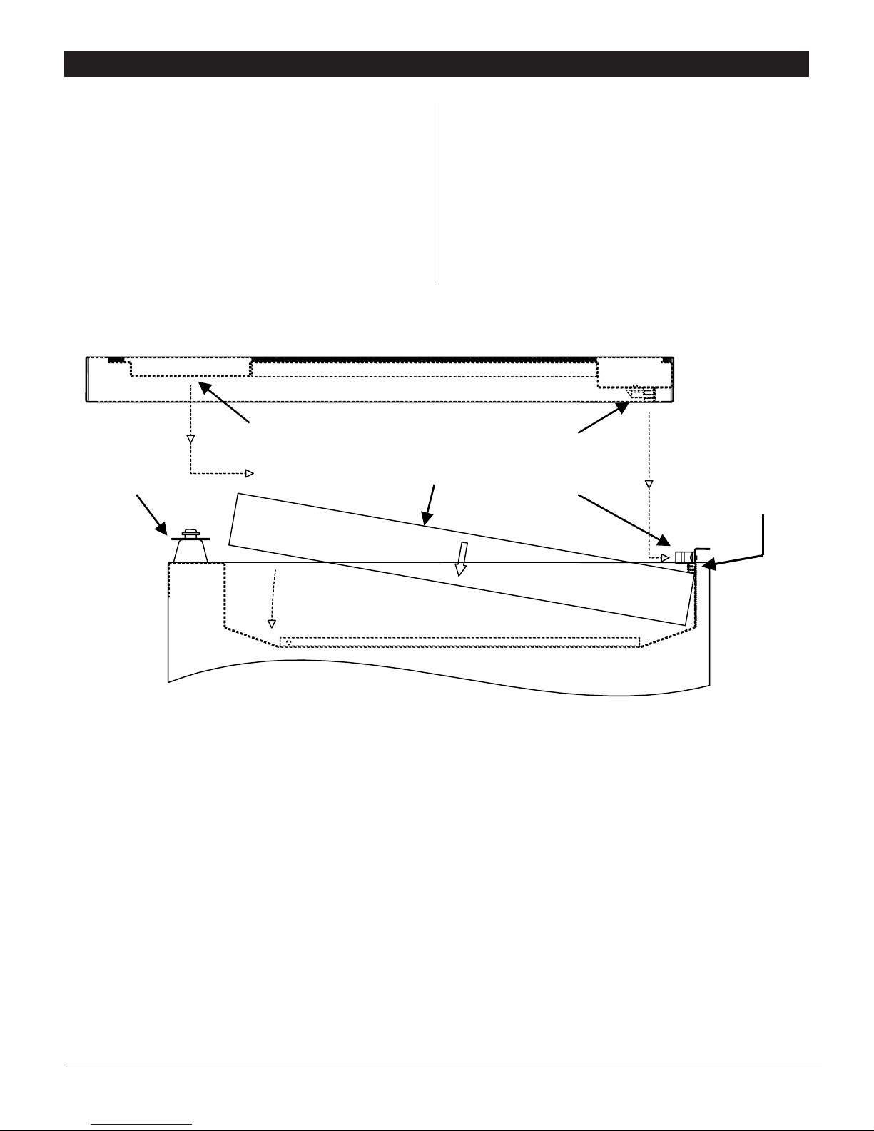
Air exiting the bottom rear of the unit enters the filter frame, then
passes through the optional filter and into the room. If the filter
is dirty, air pressure builds up before the filter. To check this
pressure, remove the plastic plug from the filter frame top; you
will feel air coming out of the hole with the unit running. Place
the ping pong ball that came with the filter frame on the hole and
let go (any marked, regulation sized ping pong ball will work). If
the ball does not move or only bounces slightly and does not spin
continuously, the filter is clean enough for continued use. If the
ball floats above the hole and starts to spin and perhaps wobble
within 30 seconds, the filter needs to be changed.
5. Service
CAUTION! Servicing the Santa Fe Rx with
its high pressure refrigerant system and high voltage circuitry
presents a health hazard which could result in death,
serious bodily injury, and/or property damage. Only
qualified service people should service this unit.
5.1 Warranty
A warranty certificate has been enclosed with this unit. Read
it before any repair is initiated. If a warranty repair is required,
call the factory first at 1-800-533-7533 for warranty claim
authorization and technical assistance.
5.2 Technical Description
The Santa Fe Rx uses a refrigeration system similar to an air
conditioner’s to remove heat and moisture from incoming air, and
add heat to the air that is discharged (see figure 1).
Hot, high pressure refrigerant gas is routed from the
compressor to the condenser coil. The refrigerant is cooled and
condensed by giving up its heat to the air that is about to be
discharged from the unit.The refrigerant liquid then passes through
a filter/drier and capillary tubing which cause the refrigerant
pressure and temperature to drop. It next enters the evaporator coil
where it absorbs heat from the incoming air and evaporates.
The evaporator operates in a flooded condition, which means that
all the evaporator tubes contain liquid refrigerant during normal
operation. A flooded evaporator should maintain constant pressure
and temperature across the entire coil, from inlet to outlet.
The mixture of gas and liquid refrigerant enter the accumulator after
leaving the evaporator coil. The accumulator prevents any liquid
refrigerant from reaching the compressor. The compressor evacuates
the cool refrigerant gas from the accumulator and compresses it to a
high pressure and temperature gas to repeat the process.
FOR HVAC INSTALLER ONLY
4Santa Fe Rx Installer’s & Owner’s Manual
Santa Fe Rx with
Optional Filter Frame
Attached to Back

5.3 Troubleshooting
No dehumidification. Neither blower nor compressor run with
AUTO FAN and humidity control turned ON.
1. Unit unplugged or no power to outlet.
2. Humidity control set too high or defective (Sec. 3.1 & 5.7).
3. Loose connection in internal wiring (Fig. 2).
4. Safety float switch in remote reservoir has turned unit off
(Sec. 2.5).
No dehumidification. Compressor does not run but blower
runs with AUTO FAN and humidity control turned to ON.
1. Defective compressor run capacitor (Sec. 5.6).
2. Loose connection in compressor circuit (see Fig. 2).
3. Defective compressor overload (Sec. 5.6A).
4. Defective compressor (Sec. 5.6).
5. Defrost thermostat open (Sec. 5.8).
6. Defective relay (Sec. 5.10).
7. Pump Safety switch open (Sec. 5.9)
Blower runs with AUTO FAN, but compressor cycles on & off.
1. Low ambient temperature and/or humidity causing unit to cycle
through defrost mode.
2. Defective compressor overload (Sec. 5.6A).
3. Defective compressor (Sec. 5.6).
4. Defrost thermostat defective (Sec. 5.8).
Blower does not run with fan switch in either position.
Compressor runs briefly but cycles on & off.
1. Loose connection in blower circuit (see Fig. 2).
2. Obstruction prevents impeller rotation.
3. Defective blower (Sec. 5.5).
4. Blower switch defective.
Evaporator coil frosted continuously, low dehumidifying
capacity.
1. Defrost thermostat loose or defective (Sec. 5.8).
2. Low refrigerant charge.
3. Dirty air filter or air flow restricted (Sec. 4.1B).
5.4 Refrigerant Charging
If the refrigerant charge is lost due to service or a leak, a new
charge must be accurately weighed in. If any of the old charge
is left in the system, it must be removed before weighing in the
new charge. Follow EPA recovery regulations. Refer to the unit
nameplate for the correct charge weight and refrigerant type.
5.5 Blower Replacement
The centrifugal blower has a PSC motor and internal thermal
overload protection. If defective, the complete assembly must be
replaced.
1. Unplug the power cord.
2. Remove the unit top.
3. If optional HEPA, 95% efficient or carbon filters are attached to
the unit back, the filter(s) and their frame must be removed.
4. Remove the back cover (4 screws).
5. Remove the cabinet (6 screws).
6. Disconnect the blower leads: black from the black wire at wire
nut, and white from the run capacitor.
7. Remove the foam pieces at the blower outlet at the bottom
back to access the blower screws.
8. Remove the 4 screws holding the blower outlet flange and
remove the blower.
9. Reassembling with the new blower is the above procedure
reversed.
5.6 Compressor/Capacitor Replacement
CAUTION! ELECTRIC SHOCK HAZARD:
Electrical power must be present to perform some tests; these
test should be performed by a qualified service person.
This compressor run capacitor is accessed by following steps 1
through 4 in section 5.5 on blower replacement; the compressor
is accessed by following steps 1 through 5. This compressor is
equipped with a two terminal external overload, run capacitor, but
no start capacitor or relay (see Fig. 2).
Perform the following tests if the blower runs but the compressor
does not with the AUTO FAN and the humidity control ON.
1. Unplug the unit, follow steps 1 through 5 of section 5.5 to
access the compressor. Remove the electrical connection cover
on the compressor top.
2. Plug in the unit and turn the humidity control to ON. If the
compressor tries to start but cycles on the over load, go to
step 4. If the compressor remains silent, check for 110 volts
from compressor terminal R to overload terminal 3 using an
AC voltmeter. If voltage is resent, go to step 3. If there is no
voltage, either the pump safety switch, defrost thermostat,
low pressure control, or relay are open or there is a loose
connection in the continuity; see the appropriate section if a
defect is suspected.
3. Check continuity between overload terminals 1 and 3: if there
is none, the overload may be tripped. Wait 10 minutes and try
again. If there is still no continuity, it is defective and must be
replaced.
4. Unplug the unit, then replace the run capacitor with one of the
same microfarad rating and equal or greater voltage rating. If
such a capacitor is unavailable, a hard start kit sized for this
compressor may be used. If the compressor does not start
and run correctly, the compressor is defective and must be
replaced.
5.6A Replacing a Burned out Compressor
The refrigerant and oil mixture in a compressor is chemically very
stable under normal operating conditions. However, when an
electrical short occurs in the compressor motor, the resulting high
temperature arc causes a portion of the refrigerant oil mixture to
break down into carbonaceous sludge, a very corrosive acid and
water. These contaminants must be carefully removed otherwise
even small residues will attack replacement compressor motors
and cause failures.
FOR HVAC INSTALLER ONLY
5Santa Fe Rx Installer’s & Owner’s Manual
Other manuals for 4030440
1
Table of contents
Other Santa Fe Rx Dehumidifier manuals