sanus accents SAN55BB User manual

Milestone AV Technologies
6436 City West Parkway
Eden Prairie, MN 55344 USA
Customer Service
Asia Pacific: 86 755 8996 9226 • sanus.ap@milestone.com
accents.sanus.com
©2012 Milestone AV Technologies, a Duchossois Group Company.
All rights reserved. Accents is a Milestone brand.
All other brand names or marks are used for identification purposes and are trademarks of their respective owners.
SAN55BB Instruction Manual
(6904-002023 <01>)
Scan here to view
product demo and install
videos or visit san.us/115

6904-002023 <01>
2
0.95
24.2
IMPORTANT SAFETY INSTRUCTIONS – SAVE THESE INSTRUCTIONS – PLEASE READ ENTIRE MANUAL PRIOR TO USE
Specications
Weight capacity-DO NOT EXCEED: 58.9 kg (130lb) includes TV and any accessories
CAUTION: Avoid potential personal injuries and property damage!
ÙDo not use thisproduct for any purpose not explicitly specied by manufacturer.
ÙThewall must becapableof supporting vetimes theweight of themonitor and mount combined.
ÙThisproduct isnot designed for use in metal stud walls!
ÙIf you do not understand these instructions, or havedoubtsabout thesafety of theinstallation, assembly or use of this
product, contact Customer Serviceor call a qualied contractor.
ÙManufacturer isnot responsiblefor damageor injury caused by incorrect assembly or use.
Technical Specications
in.
mm
Required Tools
10mm
(3/8 in.)
5.5mm
(7/32 in.)
13mm
(1/2 in.)
17.24
437.9
15.94
405.0
UP TO
26.57
675.0
27.64
702.1
6.00
152.4
25.00
635.0
3.91
99.4
3.33
84.7
OFFSET

6904-002023 <01> 3
⁄ x 2¾ in. ⁄ in.
WARNING: This product contains small items that could be a choking hazard if swallowed.
Beforestarting assembly, verify all partsareincluded and undamaged.If any partsaremissing or damaged, do not return the
damaged item to your dealer; contact Customer Service. Never use damaged parts!
NOTE: M4, M6, or M8 describes thediameter, mm describes thelength of screwsthat arelabeled M# X ##mm.Not all
hardwareincluded will beused.
[01] x 1
[02] x 1[03] x 1
[04] x 4[05] x 4[06] x 4
[07] x 4[08] x 4[09] x 4[10] x 4[11] x 4
[12] x 4[13] x 4[14] x 4[15] x 4[16] x 4
Supplied Parts and Hardware
M6 x 12mm M6 x 20mm M6 x 35mm
M4 x 35mm
M4 x 12mm
M4 M6/M8
M8 x 16mm M8 x 35mm

6904-002023 <01>
4
M4/M6/M8
1-2 Attach brackets to a TV with a at back
[07, 09, 10, 12]
[02, 03]
[14, 15]
Ensurethebracketsarelevel on theback of theTV.
If you requireadditional spacefor cables, recesses, or
protrusions, choose conguration B.
[03]
[02]
Your TV type will helpyou determinewhich hardware
conguration to use.
A. Installation option without spacers(TVswith at backs)
B. Installation option using spacers(TVswith irregular
backs)
Hand thread screwsinto thethreaded insertson theback of
your TV to determinethecorrect screw diameter (M4, M6, or
M8).
CAUTION: Avoid potential personal injuries and
property damage! Verify that thereareadequatethreads
to securethebracketsto themonitor.If you encounter
resistance, stopimmediately and contact customer
service. Use theshortest screw and spacer combination to
accommodateyour needs. Using hardwarethat istoo long
may damageyour TV.
B
1-1 Select the hardware diameter and length
A
1 Select TV Hardware and Mount TV Brackets
A

6904-002023 <01> 5
M4/M6/M8
1-2 Attach brackets to a TV with an irregular back
1-3 Adjust straps
[08, 11, 13]
[02, 03]
[14, 15]
Ensurethebracket islevel on theback of theTV.
Standard congurationsareshown.
For special applications, or if you areuncertain about your
hardwareselection, contact Customer Service.
[03]
[03] [16]
[02]
[02]
For ease of access, straps should belevel with thebottom of theTV.
B

6904-002023 <01>
6
[01]
[01]
< 16 mm
(5/8 in.)
2Mount the Wall Plate
Wood stud
2-1 Locate stud
2-2 Mark the wall
Level thewall plate[01] and mark theholelocations.
2-3 Drill pilot holes
2-4 Tighten lag bolts [04]
CAUTION:
Avoid potential injuries or property damage!
Improperuse could reducetheholding powerof thelag bolt.To
avoid potential injuries or property damage
ÙDO NOT over-tighten thelag bolts[04].
ÙTighten thelag bolts[04] only until thewashers[06] are
pulled rmly against thewall plate[01].
[04] [06]
Verify thecenter of thestud using an awl, a thin nail, or an
edgeto edgestud nder.
CAUTION: Avoid potential personal injuries and property
damage!
ÙAny material covering thewall must not exceed 16 mm
(5/8 in.).
ÙMinimum wood stud size: common 51 x 102 mm (2x 4 in.)
(nominal 38 x 89 mm (1½ x 3½ in.)).
ÙMinimum spacebetween fasteners: 406 mm (16 in.).
CAUTION:
Avoid potential injuries or property damage! Pilot
holes MUST bedrilled to a depth of 75 mm (3 in.), using a 5.5 mm (⁄
in.) diameter drill bit.
75 mm
(3 in.)
5.5 mm
(7/32 in.)
13 mm
(1/2 in.)
406-609 mm
(16-24 in.)

6904-002023 <01> 7
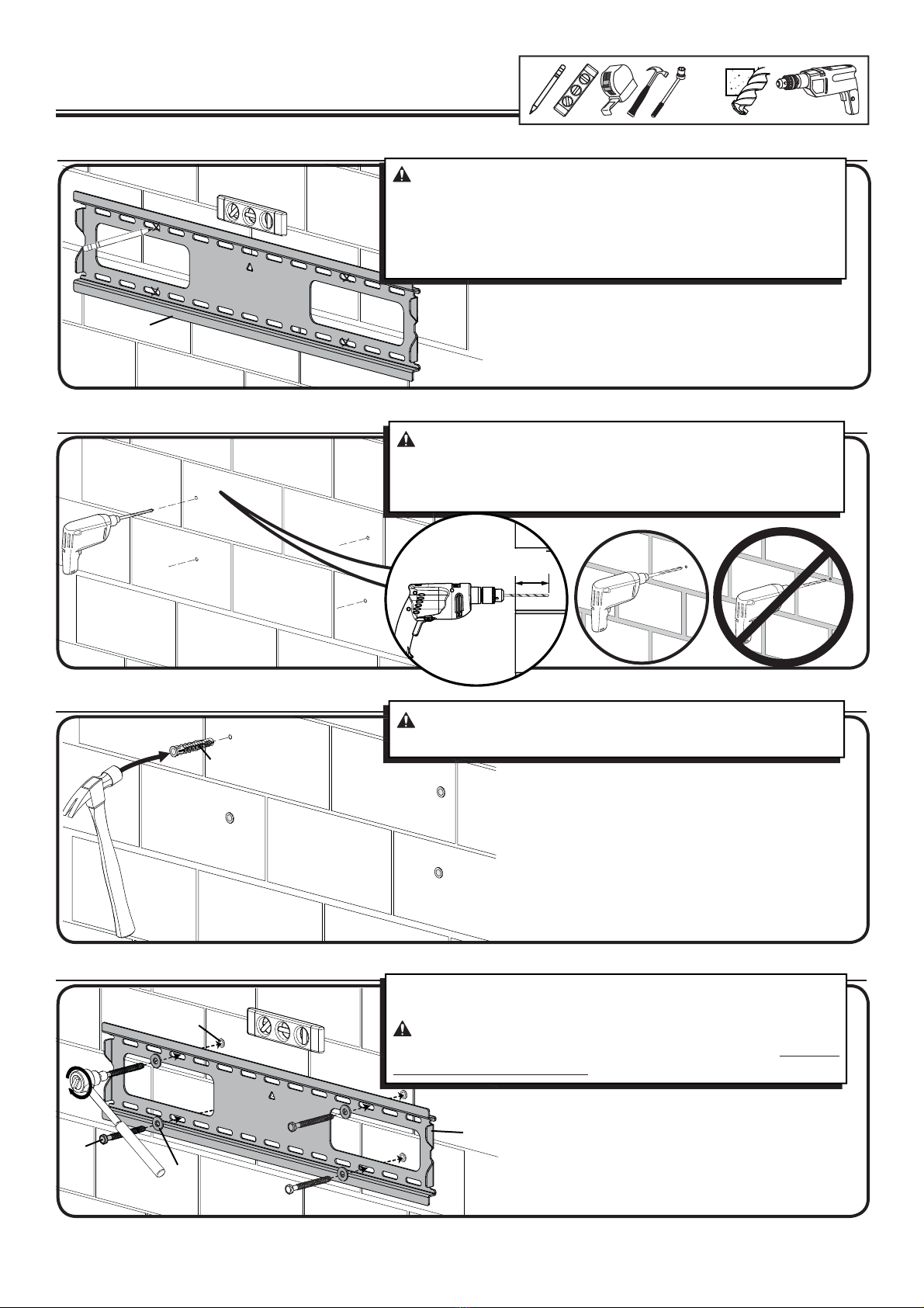
2-1 Level wall plate [01] and mark hole locations
2 Mount the Wall Plate
Solid Concrete and Concrete Block
2-2 Drill pilot holes as illustrated
2-3 Insert anchors [05]
2-4 Tighten lag bolts [04]
CAUTION: Avoid potential personal injuries and property
damage!
ÙMount thewall plate[01] directly onto theconcretesurface.
ÙMinimum solid concretethickness: 203 mm (8 in.).
ÙMinimum concreteblock size: 203 x 203 x 406 mm (8 x 8 x 16 in.).
ÙMinimum spacebetween fasteners: 406 mm (16 in.).
CAUTION: To avoid potential injuries or property damage:
ÙPilot holes MUST bedrilledto adepth of 75 mm (3 in.)using a
10mm (3/8 in.)diameterdrill bit.
ÙNeverdrill into themortar betweenblocks.
CAUTION: To avoid potential injuries or property damage:
Besuretheanchors[05] areseated ush with theconcretesurface.
[01]
[05]
[05]
[01]
[04]
[06]
Tighten lag bolts[04] only until thewashers[06] arepulled rmly
against thewall plate[01].
CAUTION: Improper use could reducetheholding power of
thelag bolt.To avoid potential injuries or property damage: DO NOT
over-tighten thelag bolts[04].
75 mm
(3 in.)
10 mm
(3/8 in.)
13 mm
(1/2in.)

6904-002023 <01>
8
[02, 03]
[02, 03]
[01]
[01]
3Hang the TV onto the Wall Plate
1 2
HEAVY! You will need
assistance with this step.
Thereisan audibleclick when thebrackets
[02, 03] aresecurely latched to thewall
plate[01].

6904-002023 <01> 9
4Adjust Level
If needed, tighten a screw on theTV brackets[02, 03] to level theTV.
[03]
[02]

6904-002023 <01>
10
MilestoneAV Technologies and itsaliated corporationsand subsidiaries (collectively, “Milestone”), intend to makethismanual accurateand complete. However, Milestonemakes no claim that theinformation
contained herein coversall details, conditions, or variations. Nor does it providefor every possiblecontingency in connection with theinstallation or use of thisproduct.Theinformation contained in this
document issubject to changewithout noticeor obligation of any kind.Milestonemakes no representation of warranty, expressed or implied, regarding theinformation contained herein.Milestoneassumes no
responsibility for accuracy, completeness or suciency of theinformation contained in thisdocument.
To removetheTV from thewall plate, simultaneously pull
release cordsdown and TV out, and then lift theTV upand out
away from thewall.
HEAVY! You will need assistance with this step.
Maintenance - Removing the TV from the Wall Plate
Table of contents
Other sanus accents TV Mount manuals