Rish INSU 10Dx+ User manual
+
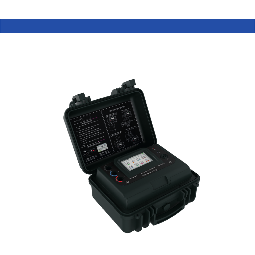
RISH INSU 10Dx
Operating Manual
10 kV Digital Insulation Tester

TABLE OF CONTENTS
Chapter 1: General Aspects………………....……………………….........................................3
1.1 Features of the meter.......………………....………………………......................................3
Chapter 2: User and Battery Safety….....………………………........................................5
Chapter 3: Basic Components and Indications in the Meter...............................7
3.1 Legends and their meanings ..........................................................................7
3.2 Basic indications and their meanings...............................................................8
Chapter 4: Connections of test leads to meter...................................................9
Chapter 5: Measurement modes of the meter..................................................11
5.1 IR Mode.....................................................................................................11
5.2 DAR Mode..................................................................................................13
5.3 PI Mode.....................................................................................................16
5.4 Step Mode.................................................................................................19
5.5 Ramp Mode................................................................................................23
5.6 Dielectric Discharge Mode ...........................................................................26
5.7 Voltage Mode ............................................................................................30
Chapter 6: Graph window................................................................................31
Chapter 7: File explorer...................................................................................34
Chapter 8: Audio read-out Feature..................................................................36
Chapter 9: Settings of the meter.....................................................................37
9.1 SLEEP Mode Settings..................................................................................37
9.2 Time/date Settings....................................................................................38
9.3 Customer information.................................................................................39
1

9.4 Brightness settings....................................................................................40
9.5 Short circuit Settings..................................................................................41
9.6 Go No Go Settings.....................................................................................42
9.7 Other Settings(Bluetooth,USB and audio read out(speaker))............................43
Chapter 10: Meter Specifications....................................................................45
Chapter 11: Battery Charging and Battery Warnings......................................48
11.1 Battery Charging Process...........................................................................48
11.2 Battery Alarms.........................................................................................48
Chapter 12: Insulation Resistance Measurement for various Equipments........49
12.1 Transformers...........................................................................................49
12.2 Circuit breakers........................................................................................50
12.3 Cables....................................................................................................50
12.4 Current transformers.................................................................................51
12.5 Motors....................................................................................................51
Chapter 13: Connection of meter with PC using USB.......................................52
Chapter 14: Connection of meter with PC using bluetooth...............................54
Chapter 15: Connection of meter with Android phone using bluetooth............58
DMAN-00IM-0901_REV_B_12_2022
2

CHAPTER 1
GENERAL ASPECTS
1.1 Features of the meter
Selectable Test Voltage up to 10000 V: Test voltages can be set to any desired value
from 100V to 10000V with steps of 10V upto 1000V and steps of 25V above 1000V.
High Insulation resistance measurement: Insulation resistance measurement from
50kΩ to 20TΩ .
Noise rejection - 8mA: High Noise immunity allows accurate measurement under noisy
environment.
Polarization Index: Polarization index (PI) testing is an extension of the insulation
resistance test and is designed to check specific issues such as moisture and insulation
deterioration.
Dielectric Absorption Ratio: DAR measurement is a diagnostic test similar to the
Polarization Index (PI), but DAR takes the ratio of the Insulation Resistance usually
measured at 30 sec and 1 min.
Dielectric Discharge Test: Dielectric Discharge(DD) test is a diagnostic insulation test
that allows aging and deterioration to be assessed.
Step Voltage Test: Step Voltage Test is designed as a controlled over-voltage or proof
test to provide an additional evaluation of the insulation system integrity.
Ramp Diagnostic Test: The Ramp Test is performed with a slowly rising voltage.
Software Selectable Filter: User selectable software filter can be used depending on
noise levels. This help in accurate reading in noisy environments.
Capacitance Measurement: Capacitance can be measured from 1nf to 50uF.
3

Go- NoGo Function: User can set an insulation resistance limit below which user will be
alarmed about the quality of insulation.
Insulation Graph Display: Insulation Resistance trend can be displayed over the time in
graphical form.
Communication Interface: Bluetooth 2.0 & 4.0 Class II and electrically isolated USB 2.0
communication.
Software and Mobile Application: It has data logging and monitoring software for
window system and an interactive mobile application for android.
File Explorer: It has file explorer to view the datalog file on TFT display.
Audio Read-Out: Audible test result on completion of test for awkward locations.
Rechargeable Battery: Li-Ion 3 Cell Battery with charging current of 1A.
Internal Data logging: It has internal data logging feature. It can log up to 2000 test
files with customer information and time stamp.
Selectable test time: User can set the test time to any desired test time from 45 sec to
99 min 59 sec.
The home screen of the meter is as shown below:
4

USER SAFETY:
Following safety measures should be taken while using the instrument:
The circuit under test should be turned off /denergized(dead), all its terminals should be
isolated, the circuit should also be discharged and checked before the insulation is tested.
During the test please make sure that you do not touch any of the test leads. The caution
symbol on the measurement screen indicates that hazardous voltage is present at the
test leads.
After test completion you should make sure that the load is completely discharged
because this charge can be dangerous.
The voltage indicator and internal discharge should be treated like additional safety
devices and not a substitute for the general practices.
Insulation testing in wet conditions can be hazardous. It is recommended that the
instrument should not be used under these circumstances.
During control from bluetooth or USB the test can be started at any time. Please make
sure the connections are proper before turning on the test.
Please use only the leads supplied with the meter for testing the device.
NOTE: INSTRUMENT SHOULD BE OPERATED BY SUITABLY TRAINED AND
COMPETENT PERSONS ONLY
BATTERY SAFETY:
Following safety measures should be followed while handling the battery:
Do not disassemble or change the battery. This battery consists of safety and protection
devices which if damaged can cause harm to the battery.
Do not heat the battery in any way.
Do not pierce the battery.
Do not expose the battery to water.
CHAPTER 2
USER AND BATTERY SAFETY
5

Do not subject the battery to shocks.
Never short circuit the battery pack.
In case the battery starts leaking, do not allow the liquid to come in contact with skin or
eyes. If by mistake you make contact, wash the affected area with water and contact
doctor.
Keep the battery away from children.
Do not expose the battery to extreme temperatures. Extreme temperature will reduce
the lifetime of the lithium ion battery.
SYMBOLS ON THE INSTRUMENT:
Caution: Please refer user manual
Caution: Risk of electrical shock
Equipment complies with current EU directives
Bluetooth
Equipment protected throughout double insulation
Do not dispose in normal waste
Audio Readout
Mains connected
Universal Serial Bus(USB)
600 V
CAT IV
Overvoltage category IV (equipment installed at or near the origin of the
electrical supply to a building) & 600V refers to the rms phase to earth voltage
that instruments can withstand to the overvoltage category IV rating.
External Voltage shall not exceed 750V
6
CHAPTER 3
BASIC COMPONENTS AND INDICATIONS IN THE METER
7
5
6
4
1
3
8
2
910 11
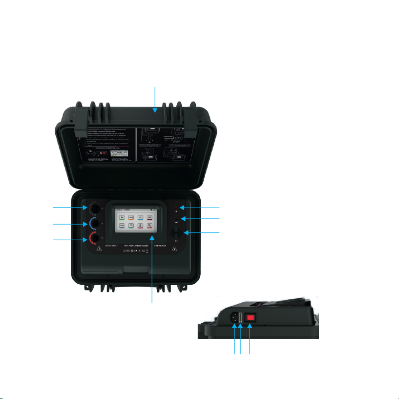
3.1 LEGENDS AND THEIR MEANING
1. Negative(-) terminal
2. Guard(G) terminal
3. Positive(+) terminal
4. LED indicating presence of mains
5. USB slot for device connection
6. Speaker
7. Protective cover
8. TFT touch screen display
9. Power supply socket
10. Fuse
11. On/Off Switch
7
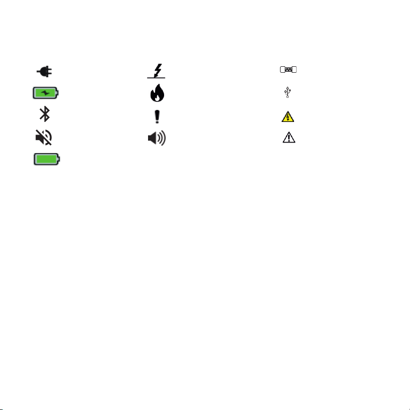
3.2 BASIC INDICATIONS AND THEIR MEANING
Mains connected
Battery charging
Bluetooth mode
Breakdown mode
Burn mode
Pre-alarm for battery
charging
Guard fuse blown
USB mode
Danger High Voltage
at leads
Speaker mute Speaker unmute Current limit warning
Battery fully
charged indication
8
CHAPTER 4
CONNECTION OF TEST LEADS TO METER
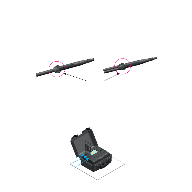
The meter has 3 probes guard, positive and negative. Each probe consists of 2 ends.
One of these ends is the probe handle which has to be connected to the meter and the other
end will depend upon the type of accessories ordered. Figure below shows the probe handle
for the single probes(Guard and positive) and double probe which is connected to the
negative terminal. Both the handles have a rotor for locking the probe to the meter
NOTE: Insulation of the DUT should be fully discharged before connecting the leads
to the DUT.
Due to the locking mechanism of the probes the probes remain firmly connected to the
meter during the test. Following are the steps to connect the probe to the meter:
Insert the probes into the meter as shown in the below diagram:
Single probe handle Double probe handle
Probe rotor
Negative
Guard
Positive
9

Then push the probes into the meter and rotate the probe rotor as shown below so that
the probe gets locked to the meter.
NOTE: Do not disconnect the test leads of the meter till the test has been completed
and the DUT has been discharged as the leads can cause electrical hazard to the
user when the test is being conducted or if the DUT is still charged.
10
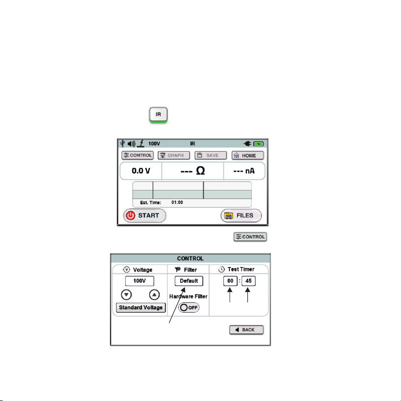
5.1 IR Mode:
This mode is used to measure the insulation resistance of a device for a fixed amount of
time. The default time of this test is 45 sec. The steps to do a test in the IR mode are as follows
To enter the IR mode press icon on the home screen. The main measurement
screen will appear.
To setup the basic settings of the mode press the icon. The control window will
appear as shown below.
Here you can set the voltage using the voltage up and down in steps of 10V below 1000V
and in steps of 25V above 1000V. There is also a standard voltage button to set standard
testing voltages (250V, 500V, 1000V, 2500V, 5000V,10000V).
CHAPTER 5
MEASUREMENT MODES OF THE METER
Software filter
button
min
button
sec
button
11

You can also change the filter settings in this window (hardware and software filter).
These filters are very useful in noisy environments. The software filter can be selected
from the drop down list which will appear after pressing the software filter button.
You can also set the test time in this mode by pressing the second or minute button. The
keyboard will appear and then you can enter the desired time between 45 sec and 99 min
59 sec and then press the button on the keyboard to set the time.
After setting up all the basic settings press the button to go back to the main
measurement screen. All these control settings are stored by the meter so that the next
time you start the meter you do not need to do these settings again.
Then connect the test leads to the equipment whose Insulation Resistance has to be
measured.
On the measurement screen press and hold the button for about 3 seconds and
then release it to start the test.
The speaker will give 3 beeps in order to indicate that the test has started. After the test
has been completed all the parameters will be displayed(according to the meter setting)
like insulation resistance, capacitance, DAR, PI, voltage, current as shown below.
12
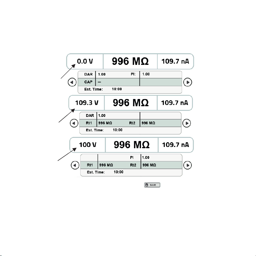
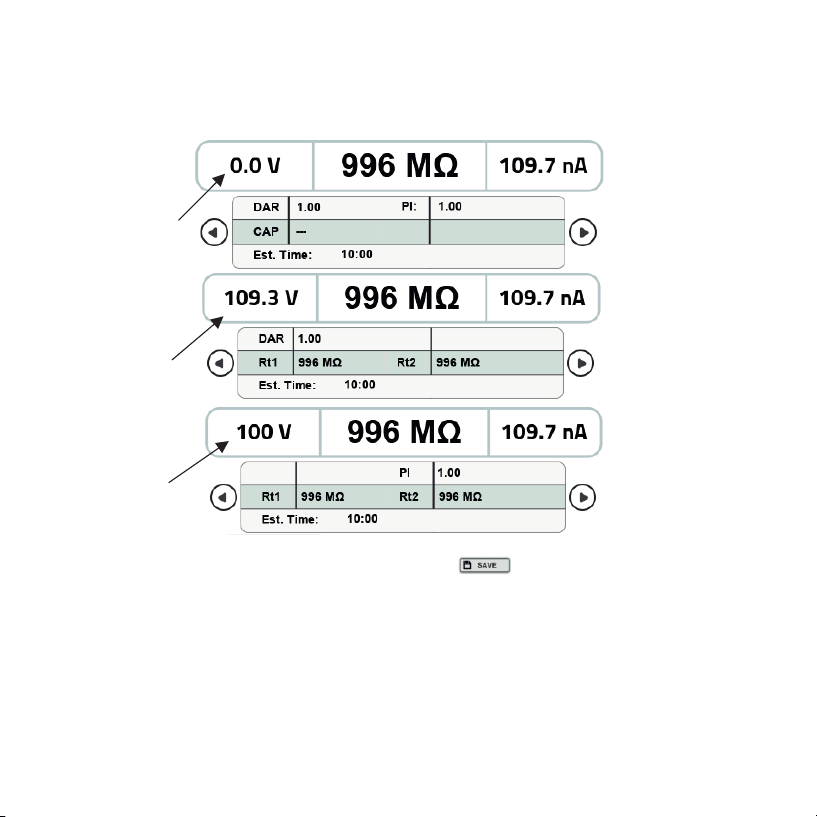
Because there are a lot of parameters to be displayed they have been divided into three
sub screens which can be scrolled using the scrolling arrows. Figure shows the sequence
of the screens along with the parameters displayed on the corresponding screen.
You can save the data of this test by pressing the button. After pressing this button
a message will appear to tell you about the file number. You can press the OK button on
the message box in order to go back to the measurement screen.
5.2 DAR Mode:
DAR(Dielectric Absorption Ratio) is defined as the ratio of insulation resistance at 1
minute divided by insulation resistance at 30 seconds. It is very useful to know the condition
of the insulation. It can be expressed in formula as:
SCREEN 1
SCREEN 2
SCREEN 3
VOLTAGE
AT LEADS
/DUT
VOLTAGE
DURING
TEST
SET
VOLTAGE
DAR
INFORMATION
PI
INFORMATION
SCREEN 1
SCREEN 2
SCREEN 3
VOLTAGE
DURING
TEST
SET
VOLTAGE
DAR
INFORMATION
PI
INFORMATION
13

DAR = IR60s / Ir30s
DAR of less than 1 indicates that the insulation is in poor condition, DAR of 1-1.4
indicates that the insulation is in good condition and DAR of greater than 1.4 indicates that
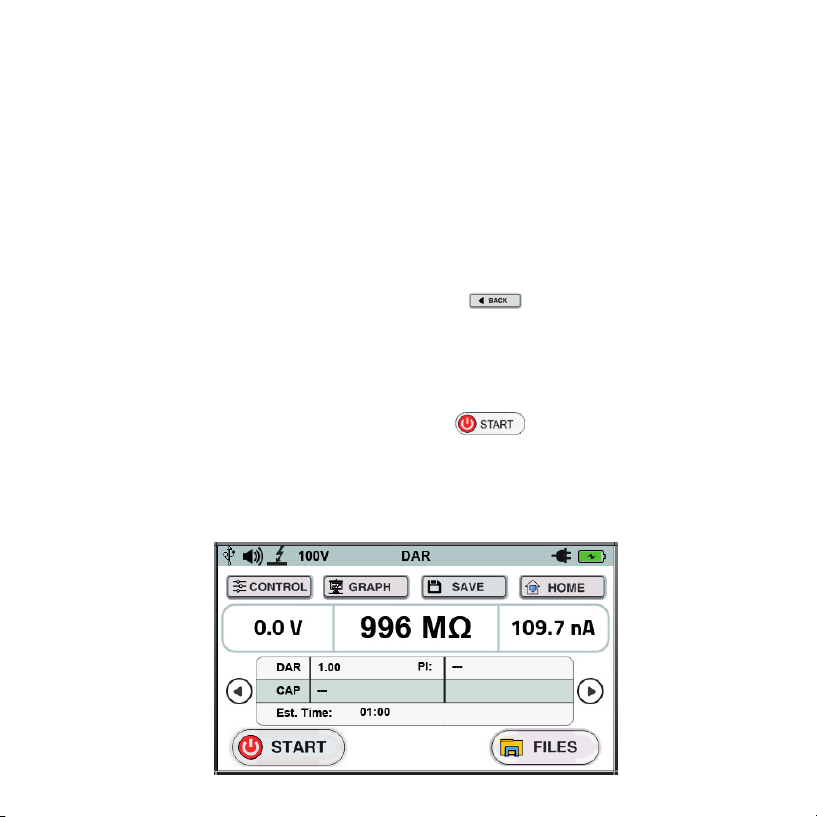
the insulation is in an excellent condition. The steps to take a test in DAR mode are as follows:
To enter the DAR mode press the icon on the home screen and following screen will
be displayed.
To setup the basic settings of the mode press the icon. The control window will
appear as shown below.
Software filter
button
14
Here you can set the voltage using the voltage up and down in steps of 10V below 1000V
and in steps of 25V above 1000V. There is also a standard voltage button to set standard
testing voltages (250V, 500V, 1000V, 2500V, 5000V,10000V).
You can also change the filter settings in this window (hardware and software filter).
These filters are very useful in noisy environments. The software filter can be selected
from the drop down list which will appear after pressing the software filter button.
As we know DAR tests are measurements of resistance over time expressed as a ratio
of resistance at time t2 divided by resistance at time t1. The t1 and t2 both can be set in
the control window with the help of their corresponding arrows. The up arrow will
increase the time and the down arrow will decrease the time.
After setting up all the basic settings press the button to go back to the main
measurement screen. All these control settings are stored by the meter so that the next
time you start the meter you do not need to do these settings again.
Then connect the test leads to the equipment whose Insulation Resistance has to be
measured.
On the measurement screen press and hold the button for about 3 seconds and
then release it to start the test.
The speaker will give 3 beeps in order to indicate that the test has started. After the test
has been completed all the parameters will be displayed(according to the meter setting)
like insulation resistance, capacitance, DAR, PI, voltage, current.
15
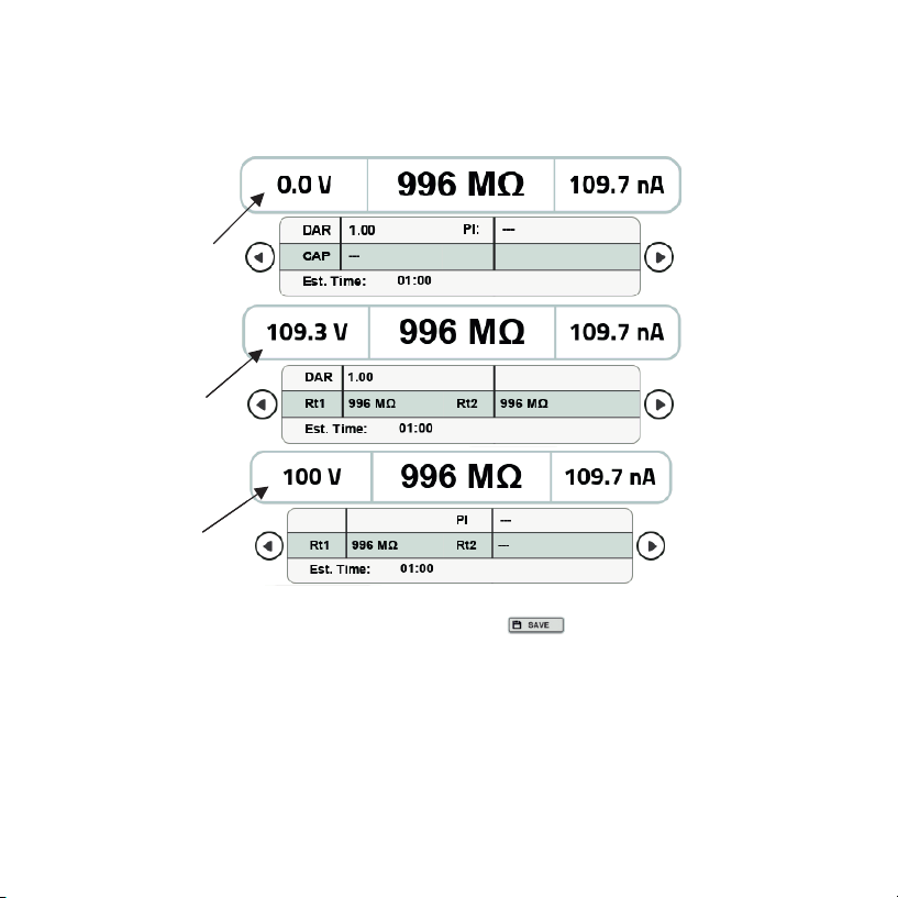
Because there are a lot of parameters to be displayed they have been divided into three
sub screens which can be scrolled using the scrolling arrows. Figure shows the sequence
of the screens along with the parameters displayed on the corresponding screen.
You can save the data of this test by pressing the button. After pressing this button
a message will appear to tell you about the file number. You can press the OK button on
the message box in order to go back to the measurement screen.
5.3 PI Mode:
PI(Polarization Index) is defined as the ratio of insulation resistance at 10 minute
divided by insulation resistance at 1 minute. It is very useful to know the condition of the
insulation. It can be expressed in formula as:
PI = IR10min / IR1min
SCREEN 1
SCREEN 2
SCREEN 3
VOLTAGE
AT LEADS
/DUT
VOLTAGE
DURING
TEST
SET
VOLTAGE
DAR
INFORMATION
PI
INFORMATION
16

PI of less than 1-2 indicates that the insulation is in poor condition, PI of 2-4 indicates
that the insulation is in good condition and PI of greater than 4 indicates that the insulation is
in an excellent condition. The steps to take a test in PI mode are as follows:
To enter the PI mode press the icon on the home screen and the following screen will
be displayed:
To setup the basic settings of the mode press the icon. The control window will
appear as shown below.
Software filter
button
17

Here you can set the voltage using the voltage up and down in steps of 10V below 1000V
and in steps of 25V above 1000V. There is also a standard voltage button to set standard
testing voltages (250V, 500V, 1000V, 2500V, 5000V,10000V).
You can also change the filter settings in this window (hardware and software filter).
These filters are very useful in noisy environments. The software filter can be selected
from the drop down list which will appear after pressing the software filter button.
As we know PI tests are measurements of resistance over time expressed as a ratio of
resistance at time t2 divided by resistance at time t1. The t1 and t2 both can be set in the
control window with the help of their corresponding arrows. The up arrow will increase
the time and the down arrow will decrease the time.
After setting up all the basic settings press the button to go back to the main
measurement screen. All these control settings are stored by the meter so that the next
time you start the meter you do not need to do these settings again.
Then connect the test leads to the equipment whose Insulation Resistance has to be
measured.
On the measurement screen press and hold the button for about 3 seconds
and then release it to start the test.
The speaker will give 3 beeps in order to indicate that the test has started. After the test
has been completed all the parameters will be displayed(according to the meter setting)
like insulation resistance, capacitance, DAR, PI, voltage, current.
18
Because there are a lot of parameters to be displayed they have been divided into
three sub screens which can be scrolled using the scrolling arrows. Figure shows the
sequence of the screens along with the parameters displayed on the corresponding
screen.
You can save the data of this test by pressing the button. After pressing this button
a message will appear to tell you about the file number. You can press the OK button on
the message box in order to go back to the measurement screen.
5.4 Step Mode:
In the step voltage test 5 test voltages are applied to the DUT. The SV test is based on
the principle that an ideal insulator will produce identical readings at all voltages, while an
insulator which is being over stressed, will show lower insulation values at higher voltages.
This test is divided into 5 intervals.
SCREEN 1
SCREEN 2
SCREEN 3
VOLTAGE
AT LEADS
/DUT
VOLTAGE
DURING
TEST
SET
VOLTAGE
DAR
INFORMATION
PI
INFORMATION
19
Table of contents
Other Rish Test Equipment manuals


Popular Test Equipment manuals by other brands


Alcohawk
Alcohawk PT400 owner's manual

Gossen MetraWatt
Gossen MetraWatt METRISO PRIME operating instructions

MULTI MEASURING INSTRUMENTS
MULTI MEASURING INSTRUMENTS MCL-800D+ instruction manual

AFRISO
AFRISO GPG 01 operating instructions

Omicron
Omicron CMC 850 quick start

YOKOGAWA
YOKOGAWA AQ1215A user manual