Sanyo Denki San Ace User manual

1
COOLING SYSTEMS Fan Instruction Manual
1. Safety Precautions
・
In order to ensure that this product is used safely, be sure that you read and
understand the following precautions fully and use the product only as directed.
・
Be sure to read these Safety Precautions carefully before installing, connecting,
operating, maintaining, or inspecting this product. Follow all the precautions and
directions given here.
・
This product has been designed and manufactured for use as a device to be
used in general industrial machinery, and may not be used as a standalone
product.
・
The product of our company (hereafter called the product) falls into the
category of the products specified in the Attached List 1, Item 16 (Class 84,
Item 14) of the Export Trade Control Ordinance. To export the product as an
individual part or to export a product into which the product is assembled, the
Information Requirements
and
Objective Requirements
that the Ministry
of Economy, Trade and Industry established based on the
Catchall Controls
must be studied for applicability. Based on information on applicability and
specified requirements, appropriate export formalities must be performed.
In order to prevent any possible bodily injury or damage to property or
equipment, the following precautions for ensuring safety are displayed
according to the following two ranks of importance:
※Note: Items marked
Warning
might also result in serious bodily injury or death in
some circumstances. Always follow the instructions for items marked
Danger
.
Handling or using the product improperly and in disregard of the
instructions with this mark might result in serious bodily injury or death.
Handling or using the product improperly and in disregard of the
instructions with this mark might result in bodily injury or physical
damage.
Dange
r
Warning
Descriptions of the precautions to be taken to ensure safety are given
below.
Dange
r
・If the product is used in medical appliances or other types of equipment
that affect people's lives, sufficient safety-related evaluations and
preparations must be made in advance, and the product or the type of
equipment into which the product is assembled must be used on the
user's own responsibility.
・If the product is used in types of equipment that have a strong social
and public impact, sufficient prior evaluations and safety-related
evaluations and preparations must be made, and the product or the type
of equipment into which the product is assembled must be used on the
user's own responsibility.
・If the product is used in an environment where there are vibrations, for
example, in a car or aboard a ship, sufficient prior evaluations and safety-
related evaluations and preparations must be made, and the product or
the piece of equipment into which the product is assembled must be
used on the user's own responsibility.
・Connect all wires properly and securely. Failure to do so might result in
burns, fire, or exposure to electrical shock.
・If there are any grounding taps or wires, attach all grounds securely.
Failure to do so might result in exposure to electrical shock.
・Never use in explosive atmosphere, as doing so might result in fires,
burns, or bodily injury.
・Never operate with any live wires exposed, as doing so might result in
electrical shock.
・Never allow any persons or objects to approach or come into contact
with the rotor while in operation, as doing so might result in damage or
personal injury.
・Turn off the power and stop using the product immediately if you notice
any sparks, smoke, odd odors, sounds, or anything unusual during
operation. Failure to do so might result in fire, burns, or electrical shock.
・Never allow the product to fall, topple over, or otherwise be subjected
to excessive shocks when moving it, as doing so might result in product
breakdown or substandard operation.
・The product should be handled only by personnel with sufficient training
and knowledge and under the responsibility of the end user.
・Never attempt to disassemble, repair, or alter this product in any way, as
doing so might result in fire, burns, or electrical shock.
・Dispose of the product as industrial waste. Please contact your local
government office for further details about disposal.
Warning
Handling
・Installation, placement, connections, wiring, or relocation of the product
should be performed by knowledgeable or correctly licensed personnel.
Never perform such work while the product is live as this might lead to
injury, electrical shock, burns, or fire.
・Do not use the fan if not fixed or stand in hand.
・Never allow yourself to come into contact with the ends of wires or
plugs when measuring the insulation resistance or dielectric strength
voltage. This might result in electrical shock.
・Never attempt to disassemble or alter this product in any way. Doing so
might invalidate any warranties concerning the functions or performance
of the product, and might also result in fire, burns, bodily injury, or
electrical shock.
Instruction
・If the fan stops during operation, give proper consideration to the device
for its protection.
・Never use the product at voltages, temperatures, or any other settings
which exceed those given in the product specifications. This might result
in substandard operation, breakdown, fire, bodily injury, or electrical
shock.
・The fan may fail to operate properly if there is insufficient power
capacity, because the starting current is several times larger than the
rated current will flow at the moment of the voltage is supplied to the
fan. Be sure to inquire about startup current levels for individual models.
・Do not control the speed of the fan by changing power voltage. It may
cause fan failure.
・Start up all fans at the same possible timing if two or more fans which
wind interferes with each other are installed in the device. If the fan is
exposed to wind from other fans at start up, it may cause fan failure or
the fan may not start up correctly.
・Never insert or remove any lead wires or connectors while the power
is turned on. When inserting or removing plugs or connections, always
be sure to first check that the power has been turned off and hold the
housing of the plug or connector when doing so. Failure to do so might
result in damage or exposure to electrical shock.
・Do not remove the lead wire from the frame hook. It may scratch and
damage the surface of the lead wire.
・Never remove the product identification plate or install the product so
that the identification cannot be seen after installation. This could result
in the product being improperly used, and subsequently result in fires.
・Do not push the nameplate of the DC fan with strong force. The
nameplate may break and touch the shaft.
・The product might become damaged if foreign objects or external forces
are allowed to interfere with normal fan operation.
・Do not implement ON-OFF of power supply in negative line. That might
cause damage of the fan.
Installation
・When fixing this product into place, be sure to take into consideration
the product's weight, the vibrations generated during operation, and all
other relevant factors. Failure to do so might cause the product or parts
of it to fall out of position, resulting in bodily injury or malfunction of the
product.
・Be sure to check the direction of installation (i.e., the fan), as failing to
do so might result in bodily injury or mechanical breakdown.
・In order to ensure that the product operates properly, allow spaces for
ventilation and take whatever steps necessary to prevent the entry
of foreign objects. Failure to do so might result in bodily injury or
mechanical breakdown.
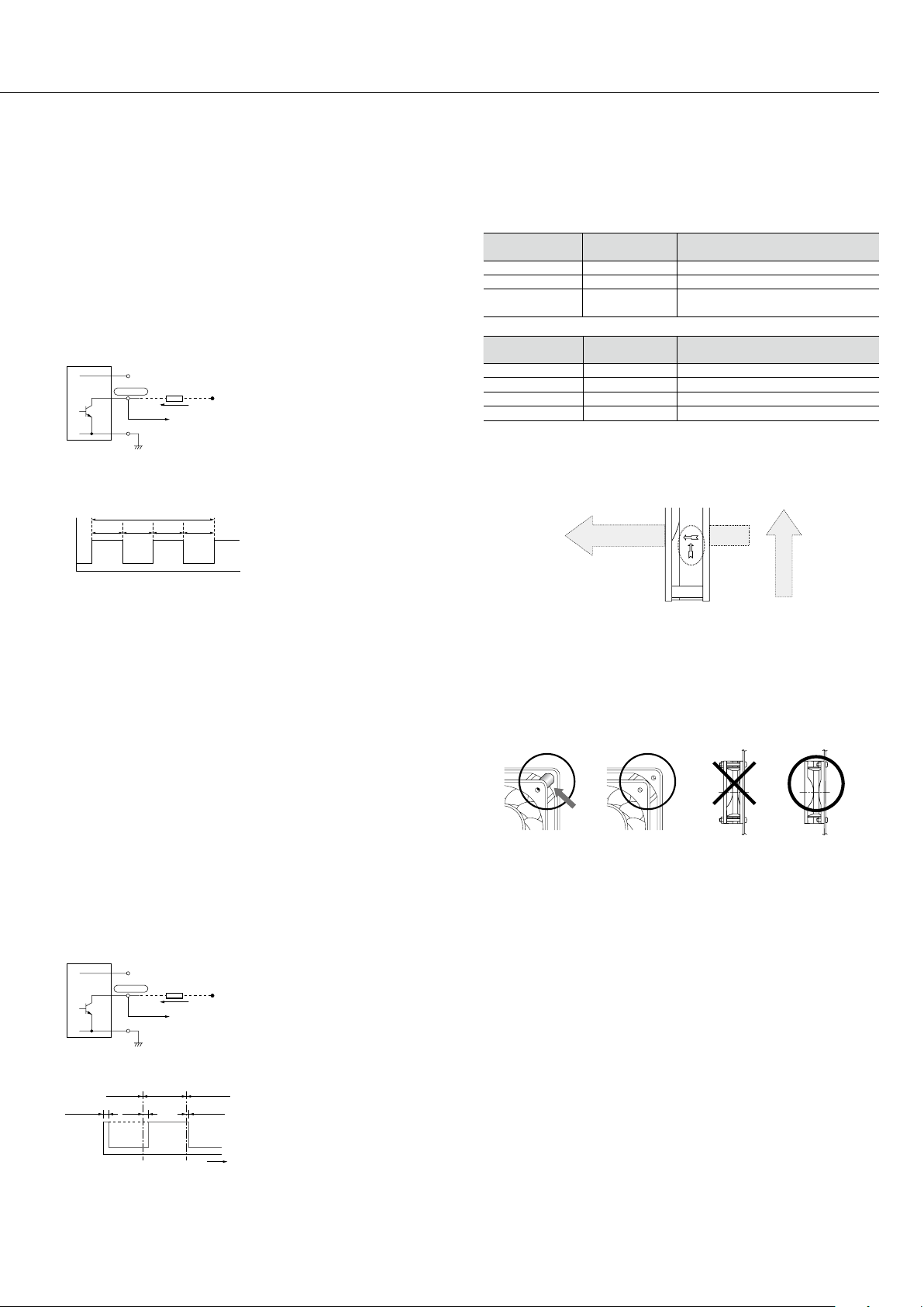
・When fixing the fan with screws, make sure the screw and sheet metal
do not deform the frame of the fan before operation. If the frame of
the fan is deformed, mechanical failure may be occurred or specified
performance may not be generated.
・When fixing the fan with screws, ensure the screwing torque. If the
screwing torque is over the recommended screw torque, fan frame
may be deformed or damaged. Use a ribbed frame when using screw
for piercing. In order to prevent from loosing screw, please use plain
washer and spring lock washer. For screwing torque of each fan type,
contact SANYO DENKI or SANYO DENKI distributor.
・When fixing the fan with self-tapping screws, fan frame may be
damaged.
・When excessive shock is attacked to fan, impeller may be protruded
from the surface of fan frame. Make sure that impeller does not touch
cover such as finger guard and mounting plate. Do not give excessive
shock to fan to avoid fan failure and deteriorate of fan performance.
・Pulling or pinching the lead wires could result in damage to the wire,
and you should avoid placing excessive stresses on these wires. The
device should also be installed so that the lead wires are not allowed to
come into contact with the rotor or blades. Failure to do so might result
in damage or exposure to electrical shock.
・Take proper precautions against static electricity when making electrical
M0011876

2
connections. Failure to do so might cause the breakdown of the fan or
device.
・Install a finger guard or other cover if there is any danger of fingers,
hands or objects coming into contact with the rotor or blades. Failure to
do so might result in bodily injury or mechanical breakdown.
・Install the finger guard, filter, and plate to the fan in the correct position
while avoiding touching of the rotor blade. Avoiding this will prevent
device failure. Please use SANYO DENKI genuine finger guards and filter
kits.
・Make electrical connections properly. If not, there is a possibility that
breakdown of device, malfunction, breakdown and deterioration of
product might cause.
Installation of Centrifugal Fan
・The fan shall be fixed with screws. For screw size of each fan type, refer
to drawing or catalog.
・Do not use the screws with length over the depth of mounting screw.
Fan might not be fixed by damaging threaded hole . For depth of
mounting screw of each fan type, refer to drawing or catalogue.
・When fixing the fan with screws, ensure the screwing torque. If the
screwing torque is over the recommended screw torque, threaded
holes may be damaged. Also, in order to prevent from loosing screw,
please use plain washer and spring lock washer. For screwing torque of
each fan type, contact SANYO DENKI or SANYO DENKI distributor.
・When excessive shock is given to fan, impeller may be protruded. Make
sure that impeller does not touch cover such as inlet nozzle and finger
guard, and mounting plate. For positional relation among the fan, inlet
nozzle, and plate of each fan type, refer to drawing or catalog.
・Install the inlet nozzle, finger guard, and plate to the fan in the correct
position while avoiding touching of the rotor blade. Avoiding this will
prevent device failure. Please use SANYO DENKI genuine inlet nozzle.
Environment of usage
・The product must not be used or stored in a flammable or corrosive
gas atmosphere, in a place where water or oil splashes (not applicable
to Splash Proof or Oil Proof Fans), in a place where there is much dust
or humidity, in a place where condensation occurs, in a place where
the product is exposed to radioactive rays or is in direct sunlight, in a
place where a salty sea breeze blows or seawater splashes, or in an
environment where the product may be contaminated by such corrosive
materials as sulfurous water, sulfurous volcanic ash, organic solvents,
acidic chemicals, alkali chemicals, etc., such hazardous substances
as nuclear fuel materials, etc. If it is used or stored in such places or
environments, there is the possibility that a fire may occur, the product
may malfunction or its performance may deteriorate.
・Avoid using or storing the product in locations and an environment
where it could be constantly exposed to vibrations, strong shocks,
magnetic or electromagnetic noise, and which the electromagnetic noise
overlaps into power voltage. This might result in product breakdown or
substandard operation.
・Avoid using or storing the product under environments where rapidly
changed such as thermal and humidity change. This might result in
product breakdown or deterioration.
Maintenance
・Maintenance and inspections should always be performed by personnel
with sufficient training and knowledge. Failure to do so might result in
fire, burns, bodily injury, or electrical shock.
・Never perform any maintenance or inspections while the product is in
operation. Also note that the blades continue to rotate for some time
immediately after operation ceases. You should always be sure to check
to see that all rotating parts have come to a stop before beginning work.
・Never use gasoline, paint thinner, benzene, or any other organic
solvents to clean the product as this could result in the deformation or
substandard operation.
2. Operating precautions
Handling explanations and precautions for the use of fans are described below.
Items without fan models are common contents.However, specifications may
differ for some model numbers. Please check the catalog or drawing for the
product specifications for the model number on the nameplate.
[1] Temperature conditions
Operating temperature: -20 ℃to +70 ℃/ -20 ℃to +60 ℃/
-10 ℃to +70 ℃/ -10 ℃to +60 ℃
(Varies for each model / Non condensing)
Storage temperature: -20 ℃to +70 ℃/ -30 ℃to +70 ℃
(Varies for each model / Non condensing)
※Rapid change in temperature may cause condensation. Prevent
condensation when storing. Condensation may affect lubrication
performance and insulation.
[2]Power specifications
For the specification of rated voltage and voltage range, please check the
catalog or drawing for the model number.
※Use of voltage exceeding the specified range may lead to performance
degradation, device failure, or fire hazards. Do not apply voltage that
exceeds specifications to the fan.
※An electronic circuit is used for the DC fan.For power supply, use
power with ripple less than 5% with low line noise and surge to prevent
electronic circuit trouble.
[3]Connection
The overview of the connection method is described below.
●AC fan
・Connection to power supply
Lead wire type: Connect AC power supply at specified voltage to lead wire
of fan motor.
Plug cord type: Connect special plug cord to power supply terminal and
connect AC power supply at specified voltage to plug cord wire.
・Connection to earth ground
Be sure to connect to earth ground through earth tapping or earth terminal
on the fan motor.
・Sensor wire
AIn the case of AC fan with sensor output, the fan has lead wire for the
sensor. Confirm "Specification for AC fan sensor" in San Ace AC fan catalog
regarding detail of sensor specification.
・Don't connect AC power supply to sensor lead wire. Fan should be broken.
AC fan AC power
Earth
●DC fan and blowers
The lead wire from the fan unit is connected to the DC power supply with
specified voltage. The red wire is +, and the black or blue wire is - (GND) in
principal.
・Sensor wire
In the case of DC fan sensor output specification, a yellow lead wire is
attached.
Connect this yellow lead wire to the receiving circuit of the sensor. Sensor
specifications differ among each model number. Do not let electric currents
above the default value flow through the lead wire of the sensor. The fan
may become damaged. For details regarding sensor specifications, refer to
the enclosed technical information "DC fan sensor specifications".
・Control line
In the case of the 2-speed fan, external
thermistor type temperature variable
speed fan or fans with PWM speed control
function, a brown lead wire is attached.
Use the brown lead wire for control. For
details regarding connection methods,
refer to the San Ace catalogue "fans
with PWM speed control function" and
technical information "the built-in / external
type temperature adjustable speed fan".
-
DC Fans
Blowers
Red
Connection schematic
Direct current
Black or Blue
●CPU cooler
The CPU cooler has lead terminal with connector at its tip. Apply specified
DC power through the connector. Yellow wire (Pin No2) is +, black wire (Pin
No1) is - (GND) in principal. Green wire (Pin No3) is pulse sensor.
※Since DC fan, blower and CPU cooler have a function of "Reverse
polarity protection", the motor doesn't break even if + and - lead wire are
connected in reverse within specified operating voltage.

3
Specifications for DC fan and blower sensors
●Pulse sensor (Tach output type) example
Pulse sensor outputs two pulse waves per revolution of fan, and it is good
to detect fan speed. Pulse sensors can be incorporated in all kinds of DC
fans.
* Noise from inside the fan or from external devices may effect sensor
output. For details, refer to specifications. The special IC that detects a
pulse sensor and raises the alarm is available.
Typical standard model: 9G1212H101
(As the following specifications differ by model no. contact us for further
information.)
Output circuit: Open collector
Specifications
VCE=+30 V MAX. (For a 48 V-rated fan: Vce=+60 V MAX.)
Ic=10 mA MAX. [Vol=Vce (SAT) =0.4V or less]
Inside of DC fan
○−
○+
Ic=10 mA MAX.
+30 V MAX.
Sensor output
Resistor
SENSOR
Output waveform (Need pull-up resistor)
In case of steady running
T1 to 4≒(1/4)T0
T1 to 4≒(1/4)T0=60/4N(sec)
N=Fan speed(min-1)
T
0
One revolution
T
1
0V
V
OL
V
OH
T
2
T
3
T
4
* If you want detailed specifications that apply when the rotor is locked,
please contact SANYO DENKI.
●Locked rotor sensor (rotation / lock detection type) example
Locked rotor sensor outputs fan status signals. It is good to check whether
the fan is running or locked
* Noise from inside the fan or from external devices may effect sensor
output.
* Regarding details of the reverse logic and specifications of lock sensor
output signals, please contact SANYO DENKI.
* Lock sensor can not be used in some models. Contact us for more
information.
Typical standard model: 9G1212H1D01
(As the following specifications differ by model no. contact us for further
information.)
Output circuit: Open collector
Specifications
VCE=+27.6 V MAX. (For a 48 V fan VCE =+60 V MAX.)
Ic=5 mA MAX. [VOL=VCE (SAT) =0.6 V or les]
(For a 48 V fan: VCE (SAT) =0.4 V or less)
Inside of DC fan
○−
○+
Ic=5mA MAX.
+
27.6V MAX.
Sensor output
Resistor
SENSOR
Output waveform (Need pull-up resistor)
VOH
VOL
0V
Time(sec)
5 or less0.5 or less 3 or less
Rotor
running
Rotor
locked
Rotor
running
Note: The output is completely at Vol with 0.5 seconds or less after
power-up.
Tightening Torque
This shows the recommended values for the tightening torque
when installing the fans. If the tightening torque is higher than the
recommended values, the fan can be deformed or damaged. Use care
when tightening. Also, be sure to always use a fan with a ribbed structure
when using screws to pass through and secure the fan.
Recommended screw torques
・DC fan
Fan mounting hole
diameter [mm]
Nominal screw
diameter
Recommended screw torque
ø3.5 M3 0.44 N・m max.
ø4.3, ø4.5 M4 0.78 N・m max.
ø4.3, ø4.5 M4
0.98 N
・
m
max.
(
ø172
×
51 mm,
ø172
×
150
×
51 mm
,
ø200
×
70 mm
)
・AC fan
Fan mounting hole
diameter [mm]
Nominal screw
diameter
Recommended screw torque
ø3.5, ø3.7 M3 0.44 N・m max.
ø4.3 M4
0.58 N
・
m max.
(
120mm
×
120mm max.
)
ø4.3 M4 0.78 N・m max.(ACDC fan, ø172 mm)
ø5.5 M4,M5 0.78 N・m max.(160mm ×160mm)
Installation
There are no limitations on the installation direction of fans or blowers. Fans
have symbols on the fan indicating the airflow direction and blade rotation
direction. When installing, use these symbols to check the airflow direction.
Air Flow direction
Symbols indicating the fan airflow direction and blade rotation direction
Blade rotation direction
Suction sideDischarge side
Comparison of ribbed and ribless structures
Regarding plastic frame, we have a option ribbed and ribless about
mounting. Please use preferred type up to your application. Please use
ribbed fan in case that you hook fan up clamping either side fan mounting
hole target. (According to the model, only models with or without ribs are
available.)
* Use a fan with a rib structure when using a screw for piercing.
Rib
Ribbed Ribless
Secur
ing with flanges
on both sides
Securing with a flang
e
on one side
Handling precautions
The fan motor is equipped with a precision ball bearing. Therefore, please
handle the motors carefully in order not to shock the bearings.
3. Overheating protection function
Protection Functions:
If the fan blades are restricted, an overcurrent occurs and leads to a rise in
the fan coil temperature. This can result in reduced performance, damage,
or a fire. To prevent this from occurring, SANYO DENKI
s fans incorporate
an overheating protection function. Refer to the catalog for the types of
protection functions.
●The burnout protective function of the AC fan
・Impedance protection (60mm sq. 80mm sq. 92mm sq. 120mm sq.)
This system is used for shading coil-type fans. When the blades are
restricted, the current is reduced by the impedance of the coil itself to
prevent a temperature rise in the coil. However, if the applied voltage
exceeds the specification range, an overcurrent can occur and result in
overheating, and so care needs to be taken.
・Thermal protection (160mm sq. φ172mm)
This system is used for condenser phase-type fans. A temperature sensor is
incorporated in the coil so that if the temperature exceeds the specification
temperature, the current is cut off to prevent overheating of the coil.
●The burnout protective function of the DC fan and blower
・Current cutoff system
If the fan blades are restricted, the coil current is cut off at regular cycles
to prevent overheating of the coil. When the hindrance is removed, the fan
restarts automatically.

4
2017.9
4. Precautions regarding dropping and rollover
Avoid impact of dropping or rollover to the fan.Precision ball bearings are used
for the bearing of the fan.
When an impact is added, the bearing suffers damage, and may lead to
the degradation of product performance, such as extraordinary noise and
shortening of life expectancy. Follow the next conditions with extra caution
when handling transportation and installation.
・The dropping limitation of the product stand-alone: The maximum limit of
dropping height is 3 cm.
・The external force limitation of the product stand-alone: A weight of 100
g dropped from a height of 3 cm above the product stand-alone is the
maximum limit. A force of 5 kgf to the fan blade is the maximum limit.
・The dropping limitation in a packaged condition: The maximum limit of
dropping height is 30 cm.
5. Other precautions
・Regarding CPU cooler that low thermal resistance pad (Thermal Pad) is
attached, take care of handling in order not to scratch it. If the low thermal
resistance pad scratches, there is a possibility that it doesn't have enough
cooling performance.
・The specification value of the maximum air volume and maximum static
pressure that is described in the catalog is a standard value at normal
temperature.Please consider enough margins when selecting a fan.
・When the fan is used in the vicinity of a power switching circuit, refer to
San Ace catalogue technical material "Cautions for use of a cooling fan in the
vicinity of a power switching circuit".
6. Options
The following options are available. Please utilize if necessary.
All-in-one fan packs with a fan and finger guard are available upon request.
Only this model includes mounting screws and nuts for assembling.
[1] The finger guard
This is an option that prevents foreign objects, such as fingers, to make
contact with the blade of the fan while in operation.Fixes with the mounting
hole of the frame of the fan using a screw. steel types or resin (plastic) types
are available.In addition, suction side and discharge side types are available.
In the case of installation, please be careful of the direction of airflow.
Please refer to the catalog for details of model numbers and other
descriptions, and apply the correct combination.
[2] Filter kit
・A filter kit keeps air in the chassis clean by filtering dust from external air
when using suction cooling. The filter kit is attached with screws through
the fan frame mounting holes along with a finger guard. Some performance
values (airflow & static pressure) of the fan motor degrade when a filter kit is
attached.
・Resin filter kits are composed of 3 components: a guard, a filter, and a cover.
It is delivered as a finished product, decreasing assembly time for mounting. It
can be mounted by inserting screws through the apertures of the cover.
・The filter and cover can easily be attached or removed from the guard. There
is no need for fan removal when performing filter maintenance.
・Ensure fan is disconnected from power source before exchanging filter.
・Operating temperature limit is between -10℃to +60℃. (non condensing)
・The filter will deteriorate with age, and the level of deterioration will vary
with usage conditions. Please be aware that the filter has a greater tendency
to deteriorate under high temperatures and humidity. For long-term storage,
please store within a temperature range of +10 ℃to +30 ℃, and a humidity
range of 20% to 65%. Product lifespan is two years, including time in storage.
・Cooling ability decreases with filter contamination from clogging. Filter
replacement is recommended after approximately six months of usage.
Replace the filter earlier if deterioration or clogging is observed during
inspection.
・When replacing the filter, use only genuine SANYO DENKI filters.
・Do not water-wash the filter.
・Avoid use and storage in high temperature or humid conditions, under direct
sunlight or exposure to ultraviolet light, or in the presence of corrosive gas.
Small pan-head screws(4)
Hexagonal nuts(4)
Filter kits
Chassis
Fan
For fixing screws
Apertures(4 locations)
[3] Plug cord
・Plug cord is one of the option to supply AC power to AC fan that power supply
input is terminal type. Plug shall be inserted to AC fan and specified power
shall be applied to code. There is a lineup of plug cord with overseas safety
standard as well. Please refer to the San Ace AC fan catalog for details of
model numbers and other descriptions, and apply the correct combination.
[4] Thermistor
・Thermistor is one of the option for thermally speed control fan with external
thermistor type. Please refer to the San Ace DC fan catalog for details.
Popular Computer Hardware manuals by other brands

Harman
Harman BSS DCP-555 installation guide

Delta Electronics
Delta Electronics Communication Module RTU-485 instruction sheet

hilscher
hilscher CIFX HPCIE90-DN/F user manual

Delta Electronics
Delta Electronics Pulse Generator Card EME-PG01 instruction sheet

Gigabyte
Gigabyte GC-CI11M-B installation guide

Radica Games
Radica Games DAVID-II 716 Operating and maintenance instruction manual