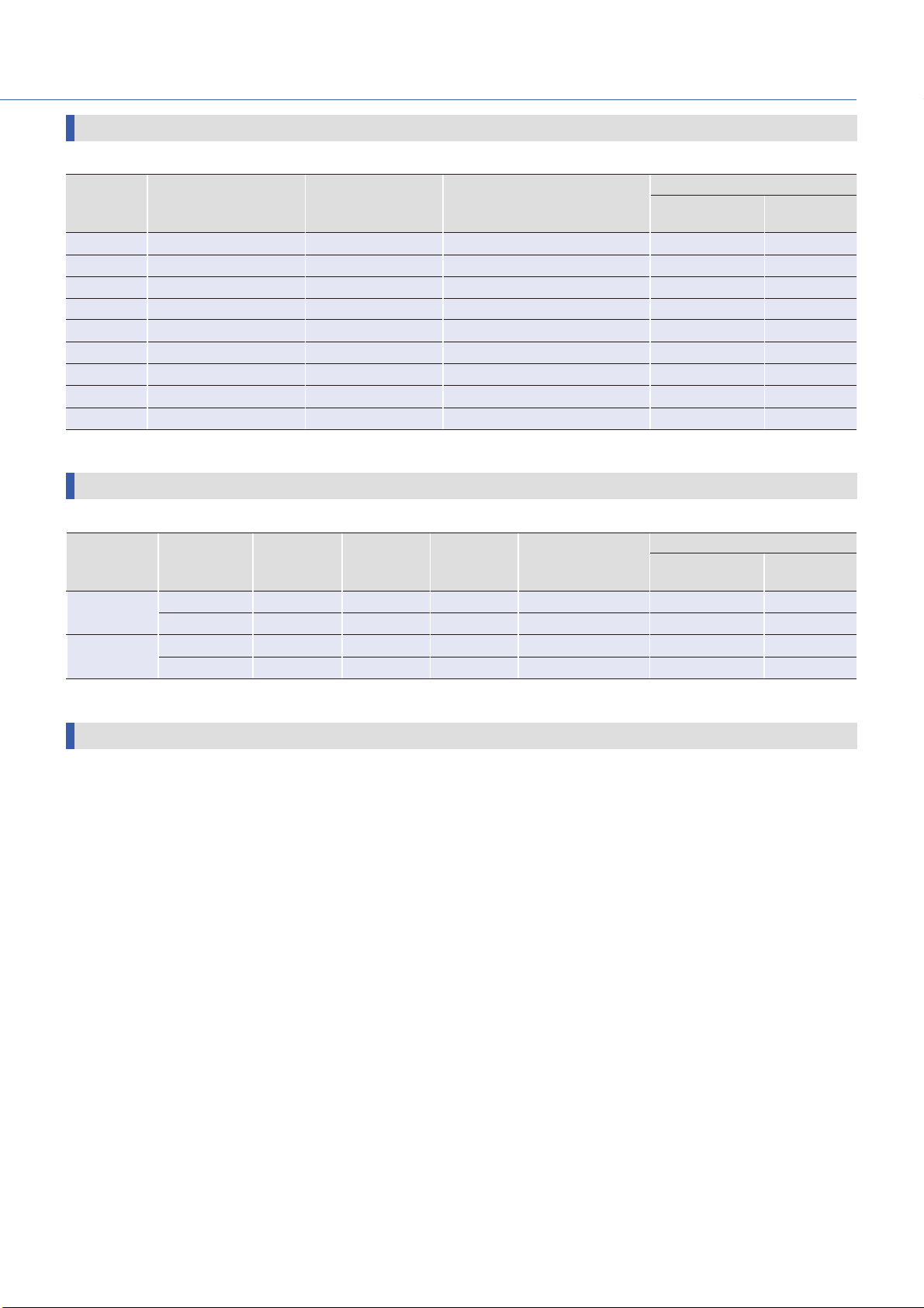
Sanyo Denki SANMOTION F5 User manual

5-PHASE STEPPING SYSTEMS

AC input Set model
Micro step
DC input Set model
Micro step, full step / half step
AC input Driver
DC input Driver
Stepping Motor
28mm sq. to 60mm sq. , φ60mm to φ106mm
Linear Actuator Stepping Motor,
Stepping Motor for vacuum environment
F50表1〜表4.inddH3-H4 2013/06/2811:28:01

3
Features ・・・・・・・・・・・・・・・・・・・・・・・・・・・・・・・P. 4
Line Up ・・・・・・・・・・・・・・・・・・・・・・・・・・・・・・・・P. 5
Lineup Details
・・・・・・・・・・・・・・・・・・・・・・・・・・P. 6
AC input Set model Micro step ・・・・・・・・・・・P. 8
System Conguration・・・・・・・・・・・・・・・・・・・・・・・・P. 8
Model number convention ・・・・・・・・・・・・・・・・・・・P. 9
Set Model Conguration ・・・・・・・・・・・・・・・・・・・・・P. 1 0
Optional Accessories
・・・・・・・・・・・・・・・・・・・・・・・・・P. 11
Specications Standard model ・・・・・・・・・・・・・・・P. 1 2
Specications CE / UL model
・・・・・・・・・・・・・・・・・P. 1 5
Specications Low-backlash gear model
・・・・・・P. 1 8
Specications Harmonic gear model ・・・・・・・・・P. 23
Specications Electromagnetic brake model
・・P. 25
Motor specications ・・・・・・・・・・・・・・・・・・・・・・・・・P. 28
Driver specications ・・・・・・・・・・・・・・・・・・・・・・・・・P. 29
Driver Controls and Connectors ・・・・・・・・・・・・・・P. 30
Connections and Signals
・・・・・・・・・・・・・・・・・・・・・P. 31
DC input Set model Micro step ・・・・・・・・・・・P. 34
System Conguration・・・・・・・・・・・・・・・・・・・・・・・・P. 34
Model number convention ・・・・・・・・・・・・・・・・・・・P. 35
Set Model Conguration ・・・・・・・・・・・・・・・・・・・・・P. 36
Optional Accessories
・・・・・・・・・・・・・・・・・・・・・・・・・P. 37
Specications Standard model ・・・・・・・・・・・・・・・P. 38
Specications Low-backlash gear model
・・・・・・P. 41
Specications Spur gear model ・・・・・・・・・・・・・・ P. 46
Specications Harmonic gear model ・・・・・・・・・P. 48
Specications Electromagnetic brake model
・・P. 51
Motor specications ・・・・・・・・・・・・・・・・・・・・・・・・・P. 53
Driver specications ・・・・・・・・・・・・・・・・・・・・・・・・・P. 54
Driver Controls and Connectors ・・・・・・・・・・・・・・P. 55
Connections and Signals
・・・・・・・・・・・・・・・・・・・・・P. 56
DC input Set model
Full/half step
・・・・・・・・・・・・P. 60
System Conguration・・・・・・・・・・・・・・・・・・・・・・・・P. 60
Model number convention ・・・・・・・・・・・・・・・・・・・P. 61
Set Model Conguration ・・・・・・・・・・・・・・・・・・・・・P. 62
Specications Standard model ・・・・・・・・・・・・・・・P. 63
Specications Low-backlash gear model
・・・・・・P. 66
Specications Spur gear model ・・・・・・・・・・・・・・ P. 71
Specications Harmonic gear model ・・・・・・・・・P. 73
Specications Electromagnetic brake model
・・P. 7 6
Motor specications ・・・・・・・・・・・・・・・・・・・・・・・・・P. 78
Driver specications ・・・・・・・・・・・・・・・・・・・・・・・・・P. 79
Driver Controls and Connectors ・・・・・・・・・・・・・・P. 80
Connections and Signals
・・・・・・・・・・・・・・・・・・・・・P. 81
Stepping Motor ・・・・・・・・・・・・・・・・・・・・・・・・P. 84
Linear Actuator Stepping Motor ・・・・・・・・P. 95
Stepping Motor for vacuum environment
・・P. 96
Dimensions ・・・・・・・・・・・・・・・・・・・・・・・・・・・・P. 97
Safety Consideration ・・・・・・・・・・・・・・・・・・・P. 1 0 7
Index

4
SANMOTION F5 is a five-phase stepping system that provides precise positioning with simple control.
The typical basic step angle is 0.72°, precisely controlled by pulse signals.
Host Devices
PLC, etc
Driver Motor
Optional
Accessories
Gear
Electromagnetic
brake
Encoder
Pulse signal
■Automicro function
■Small driver and motor, yet high torque.
■Fast response provides shorter system cycle time for repetitive operations.
■Holding torque maintains the stop position when turning on power. Electromagnetic brake
models maintain position even with power off.
Safety standards
All SANMOTION F5 drivers are specified according to standards, and comply with
UL and CE (EN standards).
You can select driver/motor sets that comply UL and CE standards.
Smooth drive is provided even with coarse resolution of one division (full-step) or two (half-step) settings.
Vibration suppression is executed internally and independently from the controller.
■Microstepping system
Multiples of the 0.72
°
basic step angle resolution can be set in 16 steps from 1 to 250 divisions. (0.72
°
to 0.00288
°
/ pulse)
Provides smooth drive with low vibration.
For DC input, only specific model (micro-step)
Features

55
Line up
Harmonic gear model
This model employs harmonic gears for
up to 1:100 resolution.
Motor size 42mm sq. (1.65inch sq.)/60mm sq.
(2.36inch sq.)/
φ
86mm (
φ
3.39inch)
Reduction gear ratios 1:30 / 1:50 / 1:100
Harmonic gear model
This model employs harmonic gears for
up to 1:100 resolution.
Motor size
28mm sq. (1.10inch sq.)/42mm sq.
(1.65inch sq.)/60mm sq. (2.36inch sq.)/
φ
86mm
(
φ
3.39inch)
Reduction gear ratios 1:30 / 1:50 / 1:100
Electromagnetic brake model
This set utilizes a non-excitation
electromagnetic brake to maintain
position in vertical load applications
and hold load even during power off.
Motor size 42mm sq. (1.65inch sq.)/60mm sq.
(2.36inch sq.)/
φ
86mm (
φ
3.39inch)
Electromagnetic brake model
This set utilizes a non-excitation
electromagnetic brake to maintain
position in vertical load applications
and hold load even during power off.
Motor size
42mm sq. (1.65inch sq.)/60mm sq.
(2.36inch sq.)/
φ
86mm (
φ
3.39inch)
Low-backlash gear model
This set employs low backlash conically
hobbed gears to engage the output stage
of the speed reduction mechanism.
Motor size
42mm sq. (1.65inch sq.)/60mm sq.
(2.36inch sq.)/φ86mm (φ3.39inch)
Reduction gear ratios
1:3.6 / 1:7.2 / 1:10 / 1:20 / 1:30 / 1:36
Low-backlash gear model
This set employs low backlash conically
hobbed gears to engage the output stage
of the speed reduction mechanism.
Motor size
42mm sq. (1.65inch sq.)/60mm sq.
(2.36inch sq.)/
φ
86mm (
φ
3.39inch)
Reduction gear ratios
1:3.6 / 1:7.2 / 1:10 / 1:20 / 1:30 / 1:36
Spur gear model
This set employs a spur gear in the
speed reduction mechanism.
Motor size 28mm sq. (1.10inch sq.)
Reduction gear ratios 1:3.6 / 1:7.2 / 1:10 /
1:20 / 1:30 / 1:50
When ordering a motor only, select from
a variety of motor sizes.
Separate driver is required.
Motor size
28mm sq. (1.10inch sq.)/
39mm sq. (1.54inch sq.)/
42mm sq. (1.65inch sq.)/
50mm sq. (1.97inch sq.)/
60mm sq. (2.36inch sq.)/
φ
60mm (
φ
2.36inch)/
φ
86mm (
φ
3.39inch)/
φ
106mm (
φ
4.17inch)
This motor is customized for use
in systems operating in vacuum
environments.
Separate driver is required.
AC input (Micro step) DC input
(42mm sq. (1.65inch sq.)/60mm sq. (2.36inch sq.))
Standard model
This is the basic model AC driver/motor
set.
Motor size
42mm sq. (1.65inch sq.)/60mm sq. (2.36inch sq.)/
φ
86mm (
φ
3.39inch)/
φ
106mm (
φ
4.17inch)
Standard model
This is the basic model DC driver/motor
set.
Motor size
28mm sq. (1.10inch sq.)/42mm sq. (1.65inch sq.)/
60mm sq. (2.36inch sq.)/
φ
86mm (
φ
3.39inch)
Motor/driver sets are conveniently available in either AC or DC models.
DC models include micro-step and full-/half-step drivers.
Beside the set models, stepping motors can be purchased independently.
The product line includes linear actuator stepping motors with straight line drives, and vacuum-compatible stepping
motors.
Set model
Stepping motor for vacuum
environment
This motor employs an integrated ball
screw for linear motion.
Separate driver is required.
Motor size
42mm sq. (1.65inch sq.)/
60mm sq. (2.36inch sq.)
CE / UL model
This model motor/driver set complies
with CE and UL standards.
Motor size
42mm sq. (1.65inch sq.)/60mm sq. (2.36inch sq.)/
φ
86mm (
φ
3.39inch)/φ106mm (
φ
4.17inch)
Stepping Motor Linear Actuator
Stepping Motor

6
Features and Line up
Series
AC input Set model
Micro step
DC input Set model
Micro step
DC input Set model
Full / half step
Power supply Single phase AC100V to 230V DC24V/48V DC24V/36V
Number of divisions 1 to 250 5-phase mode:1 to 250
2-phase mode:0.4 to 102.4
1 (Full step),
2 (Half step)
Basic step angle 0.72°to 0.00288°/pulse
5-phase mode
:
0.72°to 0.00288°/pulse
2-phase mode:
1.8°to 0.00703125°/pulse
0.72°to 0.36°/pulse
Stepping motor connection
method※pentagon connection New pentagon connection New pentagon connection
Model
types and
corresponding
motor sizes
(reduction
ratios in
parentheses)
Standard
42mm sq. (1.65inch sq.)/60mm sq.
(2.36inch sq.)/
φ
86mm (
φ
3.39inch)/
φ
106mm (
φ
4.17inch)
28mm sq. (1.10inch sq.)/42mm sq.
(1.65inch sq.)/60mm sq. (2.36inch
sq.)/
φ
86mm (
φ
3.39inch)
28mm sq. (1.10inch sq.)/42mm sq.
(1.65inch sq.)/60mm sq. (2.36inch
sq.)/
φ
86mm (
φ
3.39inch)
CE・UL
42mm sq. (1.65inch sq.)/60mm sq.
(2.36inch sq.)/
φ
86mm (
φ
3.39inch)/
φ
106mm (
φ
4.17inch)
−−
Low-backlash gear
model
42mm sq.(1.65inch sq.)/60mm sq.
(2.36inch sq.)/
φ
86mm (
φ
3.39inch)
(1:3.6 / 1:7.2 / 1:10 / 1:20 / 1:30 / 1:36)
42mm sq. (1.65inch sq.)/60mm sq.
(2.36inch sq.)/
φ
86mm (
φ
3.39inch)
(1:3.6 / 1:7.2 / 1:10 / 1:20 / 1:30 / 1:36)
42mm sq. (1.65inch sq.)/60mm sq.
(2.36inch sq.)/
φ
86mm (
φ
3.39inch)
(1:3.6 / 1:7.2 / 1:10 / 1:20 / 1:30 / 1:36)
Spur gear model −28mm sq. (1.10inch sq.)
(1:3.6 / 1:7.2 / 1:10 / 1:20 / 1:30 / 1:50)
28mm sq. (1.10inch sq.)
(1:3.6 / 1:7.2 / 1:10 / 1:20 / 1:30 / 1:50)
Harmonic gear
model
42mm sq. (1.65inch sq.)/60mm sq.
(2.36inch sq.)/
φ
86mm (
φ
3.39inch)
(1:30 / 1:50 / 1:100)
28mm sq. (1.10inch sq.)/42mm sq.
(1.65inch sq.)/60mm sq. (2.36inch
sq.)/
φ
86mm (
φ
3.39inch)
(1:30 / 1:50 / 1:100)
28mm sq. (1.10inch sq.)/42mm sq.
(1.65inch sq.)/60mm sq. (2.36inch
sq.)/
φ
86mm (
φ
3.39inch)
(1:30 / 1:50 / 1:100)
Electromagnetic
brake model
42mm sq. (1.65inch sq.)/
60mm sq. (2.36inch sq.)/
φ86mm (φ3.39inch)
42mm sq. (1.65inch sq.)/
60mm sq. (2.36inch sq.)/
φ86mm (φ3.39inch)
42mm sq. (1.65inch sq.)/
60mm sq. (2.36inch sq.)/
φ86mm (φ3.39inch)
Control method Pulse input・Open loop Pulse input・Open loop Pulse input・Open loop
Set model conguration items Driver・Motor・Connector
Driver・Motor・
DC power cable (1m)
Motor cable (1m)
I/O signal cable (1m)
Driver・Motor
Optional Accessories
AC power cable (1 to 10m)
Motor cable (1 to 10m)
I/O signal cable (1 to 2m)
Regeneration resistor −
Page
System
Conguration P. 8 P. 3 4 P. 6 0
Set Model
Conguration P.10 P.36 P.62
Specications and
Characteristics P.12 to 27 P.38 to 52 P.6 3 to 7 7
Motor specications
・
Driver specications
・
Safety standards
P.2 8 to 2 9 P.5 3 t o 5 4 P.78 to 79
Dimensions P.97 to 105 P.97 to 105 P.97 to 105
Our stepping motors generally support one of two connection methods, called "Pentagon" and "New Pentagon."
See each motor's specications for details.
Set model P.8 -
Lineup Details

77
Connection Method: Pentagon
Basic step
angle Motor size Holding torque
(N・m) Model Number
Page
Specications and
Characteristics
Dimensions
0.36°39mm sq. (1.54inch sq.) 0.078 to 0.167 103-45 □□ -70 □0P.84P.97
0.45°φ60mm (φ2.36inch) 0.91 103-7566-70 □1P.85P.99
0.72°28mm sq. (1.10inch sq.) 0.041 to 0.085 SH528 □-□0□1P.86P.97
0.72°42mm sq. (1.65inch sq.) 0.127 to 0.255 103H55 □□ -70 □0P.87P.97
0.72°50mm sq. (1.97inch sq.) 0.225 to 0.39 103H650 □-□0□1P.88P.98
0.72°60mm sq. (2.36inch sq.) 0.65 to 1.86 103H785 □-□0□1P.89P.98
0.72°φ60mm (φ2.36inch) 0.46 to 1.568 103H752 □-□0□1P.90P.99
0.72°φ86mm (φ3.39inch) 2.06 to 6.17 103H858 □-□0□1P.91P.99
0.72°φ106mm (φ4.17inch) 10.8 to 16 103H8958 □-□0□1P.92P.100
This motor is customized for use in systems operating in vacuum environments.
Supports wide pressure range for low, high and ultra-high vacuums.
・Encoder-equipped motors are available upon request.
Stepping Motor P.84 -
Stepping motor for vacuum environment P. 9 6
Linear Actuator Stepping Motor P.95 -
Connection Method: New Pentagon
Motor size Brake Rated current
(A/phase)
Thrust
(N)
Speed
(mm/s) Model number
Page
Specications and
Characteristics
Dimensions
42mm sq.
(1.65inch sq.)
Without 0.75 370 48 SL5421-7241 P.95 P.106
W i th 0 .7 5 3 70 4 8 S L5 4 21-7 2X B 41 P. 9 5 P.10 6
60mm sq.
(2.36inch sq.)
W i th ou t 1. 4 4 5 0 6 4 S L5 6 01 - 82 41 P. 9 5 P.10 6
With 1.4 450 64 SL5601-82XB41 P.95 P.106

8
AC input Set model
Micro step
System conguration
AC input Set model
Micro step
S
et Model Conguration P.10
Specications・Characteristics P.12 to 27
Motor specications P. 2 8 Driver specications P. 2 9
Motor dimensions P.97 to 104 Driver dimensions P.10 5
■Features
・
The auto-micro function provides low vibration and smooth
drive even with coarse resolution setting of one or two divisions
(full-/half-step), and supports micro steps of 250 divisions.
・Status and alarms are displayed instantly on the driver's
two-digit alphanumeric LEDs.
■Set model conguration items
Driver
Model number:FS1W075P00
Power supply:Single phase AC100V to 230V
Motor
CE/UL models comply with the respective safety standards.
Motor size:42mm sq. (1.65inch sq.), 60mm sq. (2.36inch sq.),
φ86mm (φ3.39inch), φ106mm (φ4.17inch)
Connector Power supply, Input/output signal, Motor
・Instruction manuals can be downloaded from our website.
・Cables for motor power and input/output signals (with connectors) are
sold as options.
Driver
Motor
End-cap side
Flange side
・Low-backlash gear
・Harmonic gear
I/O signal connector
(Set model conguration items)
Power connector
(Set model conguration items)
I/O signal
cable
(Optional
Accessories)
Motor cable
(Optional Accessories)
Power supply cable
(Optional Accessories)
Pulse signal
Host Devices
AC power
Single phase
100V to 230V
PLC, etc.
Brake power source
DC24V
Required for brake-
equipped stepping
motor models.
Noise lterElectromagnetic
contactor
Molded case
circuit breaker
・Electromagnetic brake
・Encoder(option)
Motor connector
(Set model conguration items)
Protects the power
line.
Cuts off circuit in the
event of overcurrent.
Switches driver
power on/off.
Use together with a
surge protector.
Filters out incoming
noise from power
line.

9
Model number convention
Example: The model number of the set with an AC driver and motor model 103F7851-70CXA4 is composed as follows.
This motor is specied as 60mm sq. (2.36inch sq.) and 92mm (3,62inch) long (motor + gear), single shaft, with
low backlash gears.
-CX
Stepping motor size
55:42mm sq. (1.65inch sq.) 85:
φ86mm (φ3.39inch)
78:60mm sq. (2.36inch sq.) 89:
φ106mm (φ4.17inch)
Stepping motor shaft spec.
S:Single shaft D:Double shaft
Stepping motor total length (Applies to standard and CE/UL models. See the
Dimensions pages for models equipped with gears and electromagnetic brakes.)
Code
Motor size
42mm sq. (1.65inch sq.) 60mm sq. (2.36inch sq.)
φ86mm (Φ3.39inch) φ106mm (Φ4.17inch)
Motor model
number
Motor length :
mm(inch)
Motor model
number
Motor length :
mm(inch)
Motor model
number
Motor length :
mm(inch)
Motor model
number
Motor length :
mm(inch)
1103□5505 34 (1.34) 103□7851 46.5 (1.83) 103□8581 62.15 (2.45)
2103
□5508 40 (1.57) 103□7852 55 (2.17) 103□8582 92.2 (3.63) 103□89582 163.3 (6.43)
3103
□7853 87.5 (3.44) 103□8583
125.85 (4.95)
103□89583 221.3 (8.71)
4103
□5510 49 (1.93)
・Replace the box character depicted in the motor model number with 'M' for CE/UL models, and 'F' for
others.
CX:Low-backlash gear model
HX:Harmonic gear model
XB:Electromagnetic brake model
Gear ratio
3.6 to 100
FS:AC input
Stepping MotorTypes
F:Standard, with gear, and with electromagnetic brake
M:CE/UL compliant
9
AC input Set model
Micro step
DC input Set model
Micro step
DC input Set model
Full / half step
Stepping MotorLinear Actuator
Stepping Motor
Stepping motor for
vacuum environment
Dimensions
1F 78 3.6S
FS

10
AC input Set model
Micro step
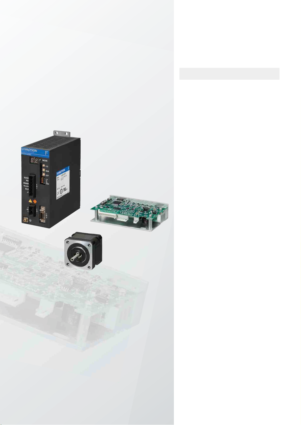
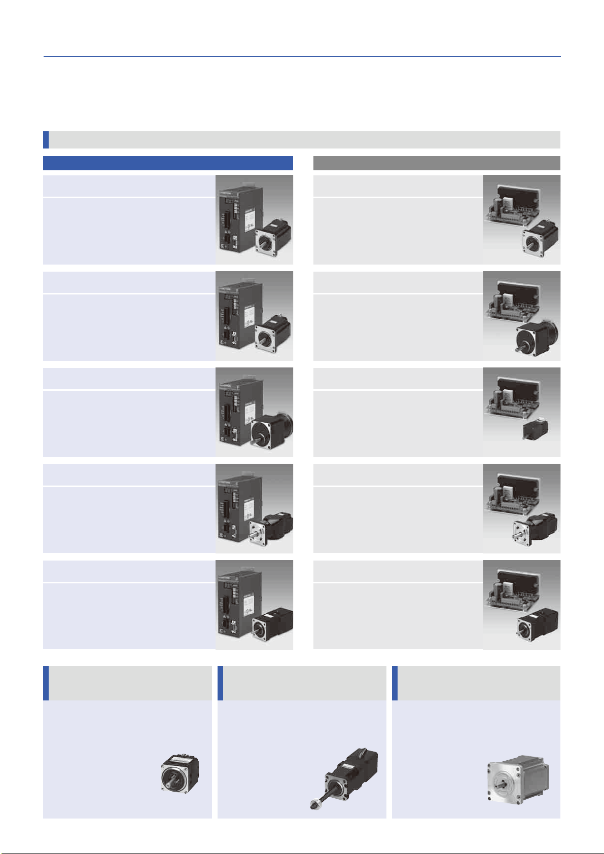
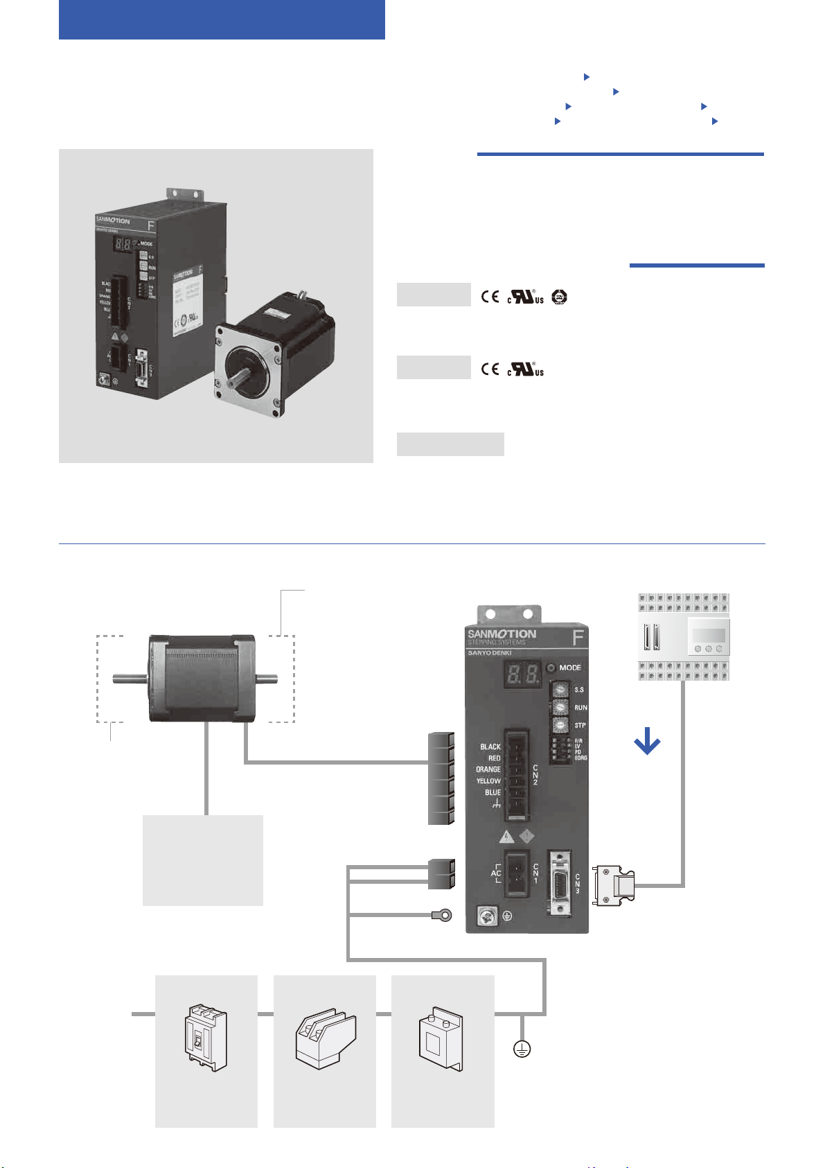
Set Model Conguration This is a set comprising a driver, motor and connectors.
AC Input Driver Model No.:FS1W075P00 Basic step angle:0.72° Rated current:0.75A/phase
Model Motor
size
Single shaft Double shaft Page
Set model
number
Set model conguration items Set model
number
Set model conguration items
Motor model
number
Connector
number
(note)
Motor model
number
Connector
number
(note)
Speci-
cations
Dimen-
sions
Standard model
42mm sq.
(1.65inch sq.)
FSF551S 103F5505-7041 PM-AP-065 FSF551D 10 3 F5 50 5 -7 011 PM -A P- 0 6 5 P.12 P. 97
FSF552S 103F5508-7041 PM-AP-065 FSF552D 10 3F 5 50 8 -7 011 P M- A P- 0 6 5 P.12 P. 97
FSF554S 103F5510-7041 PM-AP-065 FSF554D 103F5510-7011 PM-AP-065 P.12 P.97
60mm sq.
(2.36inch sq.)
FSF781S 103F7851-7041 PM-AP-064 FSF781D 10 3 F 78 51-70 11 P M- A P- 0 6 4 P.12 P. 9 8
FSF782S 103F7852-7041 PM-AP-064 FSF782D 10 3F 7 8 52-7 011 P M -A P- 0 6 4 P.13 P. 9 8
FSF783S 103F7853-7041 PM-AP-064 FSF783D 10 3 F 7 85 3 -7 011 PM - A P- 0 6 4 P.13 P. 9 8
φ86mm
(φ3.39inch)
FSF851S 103F8581-7041 PM-AP-064 FSF851D 10 3 F8 5 81-7011 PM - AP - 0 6 4 P.13 P. 99
FSF852S 103F8582-7041 PM-AP-064 FSF852D 10 3F 8 5 82-70 11 P M -A P - 0 6 4 P.13 P. 99
FSF853S 103F8583-7041 PM-AP-064 FSF853D 1 03 F8 5 8 3 -7 011 P M -A P - 0 6 4 P.14 P. 99
φ106mm
(φ4.17inch)
FSF892S 103F89582-7041 PM-AP-063 FSF892D 10 3 F8 9 5 8 2-7 011 P M -A P- 0 6 3 P.14 P.10 0
FSF893S 103F89583-7041 PM-AP-063 FSF893D 10 3 F8 9 5 8 3 -7 011 P M -A P- 0 6 3 P.14 P.10 0
CE / UL model
42mm sq.
(1.65inch sq.)
FSM551S 103M5505-7041 PM-AP-065 FSM551D 10 3M 55 0 5 -7011 P M- AP - 0 65 P.15 P.9 7
FSM552S 103M5508-7041 PM-AP-065 FSM552D 1 03 M5 5 0 8 -7011 P M- A P- 0 6 5 P.15 P. 97
FSM554S 103M5510-7041 PM-AP-065 FSM554D 103M5510-7011 PM-AP-065 P.15 P.97
60mm sq.
(2.36inch sq.)
FSM781S 103M7851-7041 PM-AP-064 FSM781D 10 3 M78 51-7 011 P M- A P- 0 6 4 P.15 P. 9 8
FSM782S 103M7852-7041 PM-AP-064 FSM782D 10 3 M7 85 2-7 011 P M- A P- 0 6 4 P.16 P. 9 8
FSM783S 103M7853-7041 PM-AP-064 FSM783D 10 3 M7 8 53 -70 11 P M -A P- 0 6 4 P.16 P.9 8
φ86mm
(φ3.39inch)
FSM851S 103M8581-7041 PM-AP-064 FSM851D 10 3M 8 5 81-70 11 P M -A P- 0 6 4 P.16 P. 9 9
FSM852S 103M8582-7041 PM-AP-064 FSM852D 10 3 M8 5 8 2-70 11 PM - AP - 0 6 4 P.16 P. 99
FSM853S 103M8583-7041 PM-AP-064 FSM853D 10 3 M 85 8 3 -7 011 P M- A P- 0 6 4 P.17 P. 9 9
φ
106mm
(φ4.17inch)
FSM892S 103M89582-7041 PM-AP-063 FSM892D 103M89582-7011 PM-AP-063 P.17 P.100
FSM893S 103M89583-7041 PM-AP-063 FSM893D 103M89583-7011 PM-AP-063 P.17 P.100
Low-backlash gear model
42mm sq.
(1.65inch sq.)
FSF551S-CX3.6 103F5505-70CXA4 PM-AP-065 FSF551D-CX3.6 10 3 F5 50 5 -7 0C X A1 P M- AP - 0 65 P.18 P.101
FSF551S-CX7.2 103F5505-70CXB4 PM-AP-065 FSF551D-CX7.2 10 3F 55 0 5 -70 CX B1 P M- AP - 0 65 P.18 P.101
FSF551S-CX10 103F5505-70CXE4 PM-AP-065 FSF551D-CX10 10 3F 5 50 5 -7 0C XE1 P M -A P- 0 6 5 P.18 P.10 1
FSF551S-CX20 103F5505-70CXG4 PM-AP-065 FSF551D-CX20 10 3F 55 0 5 -70 CXG1 PM - AP - 0 65 P.18 P.101
FSF551S-CX30 103F5505-70CXJ4 PM-AP-065 FSF551D-CX30 10 3F 5 50 5 -70 CX J1 PM - AP - 06 5 P.19 P.101
FSF551S-CX36 103F5505-70CXK4 PM-AP-065 FSF551D-CX36 10 3F 55 0 5 -70 CX K1 PM - AP - 06 5 P.19 P.101
60mm sq.
(2.36inch sq.)
FSF781S-CX3.6 103F7851-70CXA4 PM-AP-064 FSF781D-CX3.6 10 3 F 78 51-70 CX A1 P M- A P- 0 6 4 P.19 P.10 1
FSF781S-CX7.2 103F7851-70CXB4 PM-AP-064 FSF781D-CX7.2 10 3 F 78 51-7 0C XB1 P M- A P- 0 6 4 P.19 P.10 1
FSF781S-CX10 103F7851-70CXE4 PM-AP-064 FSF781D-CX10 10 3 F 78 51 -70 CX E1 P M -A P- 0 6 4 P. 2 0 P.10 1
FSF781S-CX20 103F7851-70CXG4 PM-AP-064 FSF781D-CX20 10 3 F 78 51-70 CXG1 P M -A P - 0 6 4 P. 20 P.101
FSF781S-CX30 103F7851-70CXJ4 PM-AP-064 FSF781D-CX30 10 3 F 78 51 -70 CX J1 P M - AP - 0 6 4 P. 2 0 P.10 1
FSF781S-CX36 103F7851-70CXK4 PM-AP-064 FSF781D-CX36 10 3F 7 8 51-7 0 CX K1 P M- A P- 0 6 4 P. 2 0 P.10 1
φ86mm
(φ3.39inch)
FSF851S-CX3.6 103F8581-70CXA4 PM-AP-064 FSF851D-CX3.6 10 3 F8 5 81-7 0 CX A1 PM - A P- 0 6 4 P. 21 P.10 1
FSF851S-CX7.2 103F8581-70CXB4 PM-AP-064 FSF851D-CX7.2 10 3F 8 5 81-70 CX B1 P M -A P- 0 6 4 P. 21 P.101
FSF851S-CX10 103F8581-70CXE4 PM-AP-064 FSF851D-CX10 10 3 F8 5 81-7 0C XE1 P M- A P- 0 6 4 P. 21 P.101
FSF851S-CX20 103F8581-70CXG4 PM-AP-064 FSF851D-CX20 10 3F 8 5 81-70 CXG1 P M- A P- 0 6 4 P. 21 P.101
FSF851S-CX30 103F8581-70CXJ4 PM-AP-064 FSF851D-CX30 10 3 F8 5 81-70 CX J1 P M- A P- 0 6 4 P. 2 2 P.10 1
FSF851S-CX36 103F8581-70CXK4 PM-AP-064 FSF851D-CX36 10 3F 8 5 81-70 CX K1 P M -A P- 0 6 4 P. 2 2 P.1 01
Harmonic gear
model
42mm sq.
(1.65inch sq.)
FSF551S-HX30 103F5505-70HXJ5 PM-AP-065 FSF551D-HX30 10 3 F5 50 5 -7 0H XJ 2 PM -A P- 0 6 5 P. 23 P.102
FSF551S-HX50 103F5505-70HXL5 PM-AP-065 FSF551D-HX50 10 3F 55 0 5 -70 H XL 2 P M- AP - 0 65 P. 2 3 P.10 2
FSF551S-HX100 103F5505-70HXM5 PM-AP-065 FSF551D-HX100 10 3F 55 0 5 -70 H XM 2 P M- AP - 0 65 P. 2 3 P.10 2
60mm sq.
(2.36inch sq.)
FSF781S-HX50 103F7851-70HXL4 PM-AP-064 FSF781D-HX50 10 3F 7 8 51-7 0 HX L1 P M- A P- 0 6 4 P. 2 3 P.10 3
FSF781S-HX100 103F7851-70HXM4 PM-AP-064 FSF781D-HX100 10 3 F 78 51 -70 H XM1 P M- A P- 0 6 4 P. 24 P.10 3
φ86mm
(φ3.39inch)
FSF851S-HX50 103F8581-70HXL4 PM-AP-064 FSF851D-HX50 10 3 F8 5 81-7 0 HX L1 P M -A P- 0 6 4 P. 24 P.10 3
FSF851S-HX100 103F8581-70HXM4 PM-AP-064 FSF851D-HX100 10 3 F8 5 81-7 0H X M1 PM - A P- 0 6 4 P. 2 4 P.10 3
Electromagnetic brake
model
42mm sq.
(1.65inch sq.)
FSF551S-XB 103F5505-70XB41 PM-AP-065 −− −P.25 P.10 4
FSF552S-XB 103F5508-70XB41 PM-AP-065 −− −P.25 P.104
FSF554S-XB 103F5510-70XB41 PM-AP-065 −− −P. 25 P.10 4
60mm sq.
(2.36inch sq.)
FSF781S-XB 103F7851-70XB41 PM-AP-064 −− −P. 25 P.104
FSF782S-XB 103F7852-70XB41 PM-AP-064 −− −P.26 P.10 4
FSF783S-XB 103F7853-70XB41 PM-AP-064 −− −P.2 6 P.10 4
φ86mm
(φ3.39inch)
FSF851S-XB 103F8581-70XB41 PM-AP-064 −− −P.26 P.104
FSF852S-XB 103F8582-70XB41 PM-AP-064 −− −P.26 P.104
FSF853S-XB 103F8583-70XB41 PM-AP-064 −− −P.27 P.10 4
(Note) : A set of connectors (for power, and input/output signals) for the driver and motor are included in each set conguration.
Connector
number
Driver connector set model
number
Motor connector
model number
PM-AP-065
PM-AP-078
4835758-1
PM-AP-064 4837994-1
PM-AP-063 4838971-1

11
+50
L -0
Power cable
+50
L -0
Motor cable
+50
L -0
I/O signal cable
Cable length
(L)Model number
10m PM-C03P1000-05
5m PM-C03P0500-05
3m PM-C03P0300-05
1m PM-C03P0100-05
Lead wire 600V vinyl cab tire cable
3-core AWG16
(1.25mm2)
Housing 1-178128-2(AMP)
Contact 1-175218-5(AMP)
Round-type crimp contact 1.25M4(J.S.T. Mfg Co.)
・
Cables 10m (32.81 feet) or longer are available upon request.
Lead wire 600V vinyl cab tire cable
6-core AWG18
(0.75mm2)
Housing 1-178128-6(AMP)
Contact 1-175218-5(AMP)
Round-type crimp contact 1.25M4(J.S.T. Mfg Co.)
・Cables 10m (32.81 feet) or longer are available upon request.
Cable length
(L)Model number
10m PM-C06M1000-11
5m PM-C06M0500-11
3m PM-C06M0300-11
1m PM-C06M0100-11
Cable length
(L)Model number
2m PM-C14S0200-03
1m PM-C14S0100-03
Lead wire 7-pair PVC shielded cable
AWG28
(0.08mm2)
Shell 10314-52A0-008(3M)
Plug 10114-3000PE(3M)
Optional Accessories
Cables have connector at driver end.
Connector Set - Housing/Contact List
Driver connector set model
number Connector type Housing model number
(Manufacturer)
Contact model number
(Manufacturer)
PM-AP-078
power connector 1-178128-2
(AMP)1-175218-5(AMP)
I/O signal connector 10314-52A0-008
(3M)
10114-3000PE
(3M)
Motor connector model
number
Housing model number
(Manufacturer)
Contact model number
(Manufacturer) Applicable motor sizes
4835758-1 1-178128-6
(AMP)1-175216-5(AMP)42mm sq. (1.65inch sq.)
4837994-1 1-178128-6
(AMP)1-175217-5(AMP)
60mm sq. (2.36inch sq.),
φ
86mm (
φ
3.39inch)
4838971-1 1-178128-6(AMP)1-175218-5(AMP)φ106mm (φ4.17inch)
11
AC input Set model
Micro step
DC input Set model
Micro step
DC input Set model
Full / half step
Stepping MotorLinear Actuator
Stepping Motor
Stepping motor for
vacuum environment
Dimensions

12
Standard model AC input Driver(Model number:FS1W075P00)+ Standard motor
0
0.1
0.2
0.3
0.4
0.5
0.1 1 10 100
Pulse rate(kpulse/s)
0
1
2
3
4
5
6
7
8
9
10
100 1000 2000 3000 5000
Number of rotations(min−1)
Torque(N・m)
Source current(A)
10 100 1000 2000 3000 5000
Full step
Half step
Pull-out torque
Source current
0
Torque(oz・in.)
70
60
50
40
30
20
10
Full step
Half step
Pulse rate(kpulse/s)
Number of rotations(min−1)
Source current(A)
0
0.1
0.2
0.3
0.4
0.5
0.1 1 10 100 0
1
2
3
4
5
6
7
8
9
10
100 1000 2000 3000 5000
Torque(N・m)
10 100 1000 2000 3000 5000
Pull-out torque
Source current
0
Torque(oz・in.)
70
60
50
40
30
20
10
AC input Set model
Micro step
Basic step angle:0.72° Rated current:0.75A/phase
Motor size 42mm sq. (1.65inch sq.)
60mm sq. (2.36inch sq.)
Motor length 34mm (1.34inch) 40mm (1.57inch) 49mm (1.93inch) 46.5mm (1.83inch)
Single
shaft
Set ordering model no. FSF551S FSF552S FSF554S FSF781S
Corresponding motor model number
103F5505-7041 103F5508-7041 103F5510-7041 103F7851-7041
Double
shaft
Set ordering model no. FSF551D FSF552D FSF554D FSF781D
Corresponding motor model number
103F5505-7011 103F5508-7011 103F5510-7011 103F7851-7011
Holding torque N・m (OZ・in) 0.13 (18.41) 0.18 (25.49) 0.26 (36.82) 0.6 (85.0)
Rotor inertia
(OZ・in
2
)
0.03 (0.16) 0.053 (0.29) 0.065 (0.36) 0.275 (1.50)
Motor mass (Note1) kg (lbs) 0.23 (0.50) 0.28 (0.62) 0.37 (0.81) 0.6 (1.32)
Allowable thrust load N (lbs) 10 (2.25) 10 (2.25) 10 (2.25) 20 (4.5)
Allowable radial load (Note2) N (lbs) 35 (8.75) 35 (8.75) 35 (8.75) 80 (18)
(Note1) Driver mass P. 2 9
(Note2) When load is applied at 1/3 length from output shaft edge.
System configuration P. 8 Set Model Configuration P.10 Motor dimensions P. 9 7 t o 10 0 Driver dimensions P.10 5 The data are measured under the drive condition of
our company. The drive torque may very depending on the accuracy of customer -side equipment.
■Characteristics
Operating current:0.75A/phase
Use the rubber coupling
fs : Maximum self-start frequency when not loaded Full step Half stepPull-out torque Full step Half step
Source current (load applied) Full step Half stepSource current (no load) Full step Half step
FSF551S
FSF551D
FSF552S
FSF552D
FSF554S
FSF554D
FSF781S
FSF781D
AC100V
AC100V
AC100V
AC100V
AC200V
AC200V
AC200V
AC200V
Full step
Half step
Pulse rate(kpulse/s)
Number of rotations(min−1)
Torque(N・m)
0
0.1
0.2
0.3
0.4
0.5
0.1 1 10 100
100 1000 2000 3000 5000
Source current(A)
0
1
2
3
4
5
6
7
8
9
10
10 100 1000 2000 3000 5000
Pull-out torque
Source current
0
Torque(oz・in.)
70
60
50
40
30
20
10
Full step
Half step
Torque(N・m)
Pulse rate(kpulse/s)
Number of rotations(min−1)
Source current(A)
0
0.1
0.2
0.3
0.4
0.5
0.1 1 10 100 0
1
2
3
4
5
6
7
8
9
10
100 1000 2000 3000 5000
100 2000 3000 500010 1000
Pull-out torque
Source current
0
Torque(oz・in.)
70
60
50
40
30
20
10
Torque(N・m)
Pulse rate(kpulse/s)
Number of rotations(min−1)
Source current(A)
0
0.1
0.2
0.3
0.4
0.5
0.1 1 10 100 0
1
2
3
4
5
6
7
8
9
10
100 1000 2000 3000 5000
10 100 1000 2000 3000 5000
Pull-out torque
Source current
Full step
Half step
0
Torque(oz・in.)
70
60
50
40
30
20
10
Full step
Half step
Torque(N・m)
Pulse rate(kpulse/s)
Number of rotations(min−1)
Source current(A)
0
0.1
0.2
0.3
0.4
0.5
0.1 1 10 100 0
1
2
3
4
5
6
7
8
9
10
100 1000 2000 3000 5000
10 100 1000 2000 3000 5000
Pull-out torque
Source current
0
Torque(oz・in.)
70
60
50
40
30
20
10
Full step
Half step
Torque(N・m)
Pulse rate(kpulse/s)
Number of rotations(min−1)
Source current(A)
0
0.2
0.4
0.6
0.8
1.0
0.1 1 10 100 0
1
2
3
4
5
6
7
8
9
10
100 1000 2000 3000 5000
10 100 1000 2000 3000 5000
Pull-out torque
Source current
0
Torque(oz・in.)
140
120
100
80
60
40
20
Full step
Half step
Torque(N・m)
Pulse rate(kpulse/s)
Number of rotations(min−1)
Source current(A)
0
0.2
0.4
0.6
0.8
1.0
0.1 1 10 100 0
1
2
3
4
5
6
7
8
9
10
100 1000 2000 3000 5000
10 100 1000 2000 3000 5000
Pull-out torque
Source current
0
Torque(oz・in.)
140
120
100
80
60
40
20

13
AC input Set model
Micro step
DC input Set model
Micro step
DC input Set model
Full / half step
Stepping MotorLinear Actuator
Stepping Motor
Stepping motor for
vacuum environment
Dimensions
Motor size 60mm sq. (2.36inch sq.) φ86mm (φ3.39inch)
Motor length 55mm (2.17inch) 87.5mm (3.45inch) 62.15mm (2.47inch) 92.2mm (3.63inch)
Single
shaft
Set ordering model no. FSF782S FSF783S FSF851S FSF852S
Corresponding motor model number
103F7852-7041 103F7853-7041 103F8581-7041 103F8582-7041
Double
shaft
Set ordering model no. FSF782D FSF783D FSF851D FSF852D
Corresponding motor model number
103F7852-7011 103F7853-7011 103F8581-7011 103F8582-7011
Holding torque N・m (OZ・in) 0.93 (131.7) 1.79 (253.5) 2.06 (291.7) 4.02 (569.3)
Rotor inertia
×10
-4
kg・m
2
(OZ・in
2
)
0.4 (2.19) 0.84 (4.60) 1.45 (7.93) 2.9 (15.86)
Motor mass (Note1) kg (lbs) 0.78 (1.72) 1.36 (3.0) 1.5 (3.3) 2.5 (5.5)
Allowable thrust load N (lbs) 20 (4.5) 20 (4.5) 60 (13.5) 60 (13.5)
Allowable radial load (Note2) N (lbs) 80 (18) 80 (18) 220 (49.5) 220 (49.5)
(Note1) Driver mass P. 2 9
(Note2) When load is applied at 1/3 length from output shaft edge.
System configuration P. 8 Set Model Configuration P.10 Motor dimensions P. 9 7 t o 10 0 Driver dimensions P.10 5 The data are measured under the drive condition of
our company. The drive torque may very depending on the accuracy of customer -side equipment.
■Characteristics
Operating current:0.75A/phase
Use the rubber coupling
fs : Maximum self-start frequency when not loaded Full step Half stepPull-out torque Full step Half step
Source current (load applied) Full step Half stepSource current (no load) Full step Half step
FSF782S
FSF782D
FSF783S
FSF783D
FSF851S
FSF851D
FSF852S
FSF852D
AC100V
AC100V
AC100V
AC100V
AC200V
AC200V
AC200V
AC200V
Full step
Half step
Torque(N・m)
Pulse rate(kpulse/s)
Number of rotations(min−1)
Source current(A)
0
0.4
0.8
1.2
1.6
2.0
0.1 1 10 100 0
1
2
3
4
5
6
7
8
9
10
100 1000 2000 3000 5000
10 100 1000 2000 3000 5000
Pull-out torque
Source current
0
Torque(oz・in.)
250
200
150
100
50
Full step
Half step
Torque(N・m)
Pulse rate(kpulse/s)
Number of rotations(min−1)
Source current(A)
0
0.4
0.8
1.2
1.6
2.0
0.1 1 10 100 0
1
2
3
4
5
6
7
8
9
10
100 1000 2000 3000 5000
10 100 1000 2000 3000 5000
Pull-out torque
Source current
0
Torque(oz・in.)
250
200
150
100
50
Full step
Half step
Torque(N・m)
Pulse rate(kpulse/s)
Number of rotations(min−1)
Source current(A)
0
1
2
3
4
5
0.1 1 10 100 0
1
2
3
4
5
6
7
8
9
10
100 1000 2000 3000 5000
100 1000 2000 3000 500010
Pull-out torque
Source current
0
Torque(oz・in.)
700
600
500
400
300
200
100
Full step
Half step
Torque(N・m)
Pulse rate(kpulse/s)
Number of rotations(min−1)
Source current(A)
0
1
2
3
4
5
0.1 1 10 100 0
1
2
3
4
5
6
7
8
9
10
100 1000 2000 3000 5000
10 100 1000 2000 3000 5000
Pull-out torque
Source current
0
Torque(oz・in.)
700
600
500
400
300
200
100
Full step
Half step
Torque(N・m)
Pulse rate(kpulse/s)
Number of rotations(min−1)
Source current(A)
0
1
2
3
4
5
0.1 1 10 100 0
1
2
3
4
5
6
7
8
9
10
100 1000 2000 3000 5000
100
10 1000 2000 3000 5000
Pull-out torque
Source current
0
Torque(oz・in.)
700
600
500
400
300
200
100
Torque(N・m)
Pulse rate(kpulse/s)
Number of rotations(min−1)
Source current(A)
Full step
Half step
0
1
2
3
4
5
0
1
2
3
4
5
6
7
8
9
10
0.1 1 10 100
100 1000 2000 3000 5000
10 100 10002000 3000 5000
0
1
2
3
4
5
0
1
2
3
4
5
6
7
8
9
10
0.1 1 10 100
100 1000 2000 3000 5000
10 100 10002000 3000 5000
Pull-out torque
Source current
0
Torque(oz・in.)
700
600
500
400
300
200
100
Full step
Half step
Torque(N・m)
Pulse rate(kpulse/s)
Number of rotations(min−1)
Source current(A)
0
1
2
3
4
5
0.1 1 10 100 0
1
2
3
4
5
6
7
8
9
10
100 1000 2000 3000 5000
10 100 1000 20003000 5000
Pull-out torque
Source current
0
Torque(oz・in.)
700
600
500
400
300
200
100
Full step
Half step
Torque(N・m)
Pulse rate(kpulse/s)
Number of rotations(min−1)
Source current(A)
0
1
2
3
4
5
0.1 1 10 100 0
1
2
3
4
5
6
7
8
9
10
100 1000 2000 3000 5000
10 100 1000 2000 3000 5000
Pull-out torque
Source current
0
Torque(oz・in.)
700
600
500
400
300
200
100

14
Standard model AC input Driver(Model number:FS1W075P00)+ Standard motor
AC input Set model
Micro step
System configuration P. 8 Set Model Configuration P.10 Motor dimensions P. 9 7 t o 10 0 Driver dimensions P.10 5 The data are measured under the drive condition of
our company. The drive torque may very depending on the accuracy of customer -side equipment.
Basic step angle:0.72° Rated current:0.75A/phase
Motor size φ86mm (φ3.39inch) φ106mm (φ4.17inch)
Motor length 125.85mm (4.95inch) 163.3mm (6.43inch) 221.3mm (8.71inch)
Single
shaft
Set ordering model no. FSF853S FSF892S FSF893S
Corresponding motor model number
103F8583-7041 103F89582-7041 103F89583-7041
Double
shaft
Set ordering model no. FSF853D FSF892D FSF893D
Corresponding motor model number
103F8583-7011 103F89582-7011 103F89583-7011
Holding torque N・m (OZ・in) 6.17 (873.7) 10.8 (1529.4) 16 (2265.7)
Rotor inertia
×10
-4
kg・m
2
(OZ・in
2
)
4.4 (24.06) 14.6 (79.83) 22 (120.28)
Motor mass (Note1) kg (lbs) 3.5 (7.7) 7.5 (16.5) 10.5 (23.1)
Allowable thrust load N (lbs) 60 (13.5) 100 (22.5) 100 (22.5)
Allowable radial load (Note2) N (lbs) 220 (49.5) 360 (81) 360 (81)
(Note1) Driver mass P. 2 9
(Note2) When load is applied at 1/3 length from output shaft edge.
■Characteristics
FSF853S
FSF853D
FSF892S
FSF892D
FSF893S
FSF893D
AC100V
AC100V
AC100V
AC200V
AC200V
AC200V
Full step
Half step
Torque(N・m)
Pulse rate(kpulse/s)
Number of rotations(min−1)
Source current(A)
0
4
8
12
16
20
0.1 1 10 100 0
1
2
3
4
5
6
7
8
9
10
100 1000 2000 3000 5000
10 100 1000 2000 3000 5000
Pull-out torque
Source current
0
Torque(oz・in.)
2500
2000
1500
1000
550
0
4
8
12
16
20
0.1 1 10 100 0
1
2
3
4
5
6
7
8
9
10
Full step
Half step 2000 3000 500010010 1000
2000 3000 5000100 1000
Pull-out torque
Source current
0
Torque(oz・in.)
2500
2000
1500
1000
550
Torque(N・m)
Pulse rate(kpulse/s)
Number of rotations(min−1)
Source current(A)
Full step
Half step
Torque(N・m)
Pulse rate(kpulse/s)
Number of rotations(min−1)
Source current(A)
0
2
4
6
8
10
0.1 1 10 100 0
1
2
3
4
5
6
7
8
9
10
100 1000 2000 3000 5000
10 100 1000 2000 3000 5000
Pull-out torque
Source current
0
Torque(oz・in.)
1400
1200
1000
800
600
400
200
Full step
Half step
Torque(N・m)
Pulse rate(kpulse/s)
Number of rotations(min−1)
Source current(A)
0
2
4
6
8
10
0.1 1 10 100 0
1
2
3
4
5
6
7
8
9
10
100 1000 2000 3000 5000
10 100 1000 2000 3000 5000
Pull-out torque
Source current
0
Torque(oz・in.)
1400
1200
1000
800
600
400
200
Torque(N・m)
Pulse rate(kpulse/s)
Number of rotations(min−1)
Source current(A)
0
4
8
12
16
20
0.1 1 10 100 0
1
2
3
4
5
6
7
8
9
10
Full step
Half step
Pull-out torque
Source current
2000 3000 500010010 1000
2000 3000 5000100 1000
0
Torque(oz・in.)
2500
2000
1500
1000
550
Torque(N・m)
Pulse rate(kpulse/s)
Number of rotations(min−1)
Source current(A)
0
4
8
12
16
20
0.1 1 10 100 0
1
2
3
4
5
6
7
8
9
10
Full step
Half step
Pull-out torque
Source current
2000 3000 500010010 1000
2000 3000 5000100 1000
0
Torque(oz・in.)
2500
2000
1500
1000
550
Operating current:0.75A/phase
Use the rubber coupling
fs : Maximum self-start frequency when not loaded Full step Half stepPull-out torque Full step Half step
Source current (load applied) Full step Half stepSource current (no load) Full step Half step

15
CE / UL model AC input Driver(Model number:FS1W075P00)+ CE/UL Compliant Motor
AC input Set model
Micro step
DC input Set model
Micro step
DC input Set model
Full / half step
Stepping MotorLinear Actuator
Stepping Motor
Stepping motor for
vacuum environment
Dimensions
System configuration P. 8 Set Model Configuration P.10 Motor dimensions P. 9 7 t o 10 0 Driver dimensions P.10 5 The data are measured under the drive condition of
our company. The drive torque may very depending on the accuracy of customer -side equipment.
0
0.1
0.2
0.3
0.4
0.5
0.1 1 10 100
Pulse rate(kpulse/s)
0
1
2
3
4
5
6
7
8
9
10
100 1000 2000 3000 5000
Number of rotations(min−1)
Torque(N・m)
Source current(A)
10 100 1000 2000 3000 5000
Full step
Half step
Pull-out torque
Source current
0
Torque(oz・in.)
70
60
50
40
30
20
10
Full step
Half step
Pulse rate(kpulse/s)
Number of rotations(min−1)
Source current(A)
0
0.1
0.2
0.3
0.4
0.5
0.1 1 10 100 0
1
2
3
4
5
6
7
8
9
10
100 1000 2000 3000 5000
Torque(N・m)
10 100 1000 2000 3000 5000
Pull-out torque
Source current
0
Torque(oz・in.)
70
60
50
40
30
20
10
Basic step angle:0.72° Rated current:0.75A/phase
Motor size 42mm sq. (1.65inch sq.)
60mm sq.(2.36inch sq.)
Motor length 34mm (1.34inch) 40mm (1.57inch) 49mm (1.93inch) 46.5mm (1.83inch)
Single
shaft
Set ordering model no. FSM551S FSM552S FSM554S FSM781S
Corresponding motor model number
103M5505-7041 103M5508-7041 103M5510-7041 103M7851-7041
Double
shaft
Set ordering model no. FSM551D FSM552D FSM554D FSM781D
Corresponding motor model number
103M5505-7011 103M5508-7011 103M5510-7011 103M7851-7011
Holding torque N・m (OZ・in) 0.13 (18.41) 0.18 (25.49) 0.26 (36.82) 0.6 (85.0)
Rotor inertia
×10
-4
kg・m
2
(OZ・in
2
)
0.03 (0.16) 0.053 (0.29) 0.065 (0.36) 0.275 (1.50)
Motor mass (Note1) kg (lbs) 0.23 (0.51) 0.28 (0.62) 0.37 (0.81) 0.6 (1.32)
Allowable thrust load N (lbs) 10 (2.25) 10 (2.25) 10 (2.25) 20 (4.5)
Allowable radial load (Note2) N (lbs) 35 (8.75) 35 (8.75) 35 (8.75) 80 (18)
(Note1) Driver mass P. 2 9
(Note2) When load is applied at 1/3 length from output shaft edge.
■Characteristics
FSM551S
FSM551D
FSM552S
FSM552D
FSM554S
FSM554D
FSM781S
FSM781D
AC100V
AC100V
AC100V
AC100V
AC200V
AC200V
AC200V
AC200V
Full step
Half step
Pulse rate(kpulse/s)
Number of rotations(min−1)
Torque(N・m)
0
0.1
0.2
0.3
0.4
0.5
0.1 1 10 100
100 1000 2000 3000 5000
Source current(A)
0
1
2
3
4
5
6
7
8
9
10
10 100 1000 2000 3000 5000
Pull-out torque
Source current
0
Torque(oz・in.)
70
60
50
40
30
20
10
Full step
Half step
Torque(N・m)
Pulse rate(kpulse/s)
Number of rotations(min−1)
Source current(A)
0
0.1
0.2
0.3
0.4
0.5
0.1 1 10 100 0
1
2
3
4
5
6
7
8
9
10
100 1000 2000 3000 5000
100 2000 3000 500010 1000
Pull-out torque
Source current
0
Torque(oz・in.)
70
60
50
40
30
20
10
Torque(N・m)
Pulse rate(kpulse/s)
Number of rotations(min−1)
Source current(A)
0
0.1
0.2
0.3
0.4
0.5
0.1 1 10 100 0
1
2
3
4
5
6
7
8
9
10
100 1000 2000 3000 5000
10 100 1000 2000 3000 5000
Pull-out torque
Source current
Full step
Half step
0
Torque(oz・in.)
70
60
50
40
30
20
10
Full step
Half step
Torque(N・m)
Pulse rate(kpulse/s)
Number of rotations(min−1)
Source current(A)
0
0.1
0.2
0.3
0.4
0.5
0.1 1 10 100 0
1
2
3
4
5
6
7
8
9
10
100 1000 2000 3000 5000
10 100 1000 2000 3000 5000
Pull-out torque
Source current
0
Torque(oz・in.)
70
60
50
40
30
20
10
Full step
Half step
Torque(N・m)
Pulse rate(kpulse/s)
Number of rotations(min−1)
Source current(A)
0
0.2
0.4
0.6
0.8
1.0
0.1 1 10 100 0
1
2
3
4
5
6
7
8
9
10
100 1000 2000 3000 5000
10 100 1000 2000 3000 5000
Pull-out torque
Source current
0
Torque(oz・in.)
140
120
100
80
60
40
20
Full step
Half step
Torque(N・m)
Pulse rate(kpulse/s)
Number of rotations(min−1)
Source current(A)
0
0.2
0.4
0.6
0.8
1.0
0.1 1 10 100 0
1
2
3
4
5
6
7
8
9
10
100 1000 2000 3000 5000
10 100 1000 2000 3000 5000
Pull-out torque
Source current
0
Torque(oz・in.)
140
120
100
80
60
40
20
Operating current:0.75A/phase
Use the rubber coupling
fs : Maximum self-start frequency when not loaded Full step Half stepPull-out torque Full step Half step
Source current (load applied) Full step Half stepSource current (no load) Full step Half step

16
CE / UL model AC input Driver(Model number:FS1W075P00)+ CE/UL Compliant Motor
AC input Set model
Micro step
System configuration P. 8 Set Model Configuration P.10 Motor dimensions P. 9 7 t o 10 0 Driver dimensions P.10 5 The data are measured under the drive condition of
our company. The drive torque may very depending on the accuracy of customer -side equipment.
Basic step angle:0.72° Rated current:0.75A/phase
Motor size 60mm sq. (2.36inch sq.) φ86mm (φ3.39inch)
Motor length 55mm (2.17inch) 87.5mm (3.44inch) 62.15mm (2.47inch) 92.2mm (3.63inch)
Single
shaft
Set ordering model no. FSM782S FSM783S FSM851S FSM852S
Corresponding motor model number
103M7852-7041 103M7853-7041 103M8581-7041 103M8582-7041
Double
shaft
Set ordering model no. FSM782D FSM783D FSM851D FSM852D
Corresponding motor model number
103M7852-7011 103M7853-7011 103M8581-7011 103M8582-7011
Holding torque N・m (OZ・in) 0.93 (131.7) 1.79 (253.5) 2.06 (291.7) 4.02 (569.3)
Rotor inertia
×10
-4
kg・m
2
(OZ・in
2
)
0.4 (2.19) 0.84 (4.59) 1.45 (7.93) 2.9 (15.86)
Motor mass (Note1) kg (lbs) 0.78 (1.72) 1.36 (3.0) 1.5 (3.3) 2.5 (5.5)
Allowable thrust load N (lbs) 20 (4.5) 20 (4.5) 60 (13.5) 60 (13.5)
Allowable radial load (Note2) N (lbs) 80 (18) 80 (18) 220 (49.5) 220 (49.5)
(Note1) Driver mass P. 2 9
(Note2) When load is applied at 1/3 length from output shaft edge.
■Characteristics
FSM782S
FSM782D
FSM783S
FSM783D
FSM851S
FSM851D
FSM852S
FSM852D
AC100V
AC100V
AC100V
AC100V
AC200V
AC200V
AC200V
AC200V
Full step
Half step
Torque(N・m)
Pulse rate(kpulse/s)
Number of rotations(min−1)
Source current(A)
0
0.4
0.8
1.2
1.6
2.0
0.1 1 10 100 0
1
2
3
4
5
6
7
8
9
10
100 1000 2000 3000 5000
10 100 1000 2000 3000 5000
Pull-out torque
Source current
0
Torque(oz・in.)
250
200
150
100
50
Full step
Half step
Torque(N・m)
Pulse rate(kpulse/s)
Number of rotations(min−1)
Source current(A)
0
0.4
0.8
1.2
1.6
2.0
0.1 1 10 100 0
1
2
3
4
5
6
7
8
9
10
100 1000 2000 3000 5000
10 100 1000 2000 3000 5000
Pull-out torque
Source current
0
Torque(oz・in.)
250
200
150
100
50
Full step
Half step
Torque(N・m)
Pulse rate(kpulse/s)
Number of rotations(min−1)
Source current(A)
0
1
2
3
4
5
0.1 1 10 100 0
1
2
3
4
5
6
7
8
9
10
100 1000 2000 3000 5000
100 1000 2000 3000 500010
Pull-out torque
Source current
0
Torque(oz・in.)
700
600
500
400
300
200
100
Full step
Half step
Torque(N・m)
Pulse rate(kpulse/s)
Number of rotations(min−1)
Source current(A)
0
1
2
3
4
5
0.1 1 10 100 0
1
2
3
4
5
6
7
8
9
10
100 1000 2000 3000 5000
10 100 1000 2000 3000 5000
Pull-out torque
Source current
0
Torque(oz・in.)
700
600
500
400
300
200
100
Full step
Half step
Torque(N・m)
Pulse rate(kpulse/s)
Number of rotations(min−1)
Source current(A)
0
1
2
3
4
5
0.1 1 10 100 0
1
2
3
4
5
6
7
8
9
10
100 1000 2000 3000 5000
100
10 1000 2000 3000 5000
Pull-out torque
Source current
0
Torque(oz・in.)
700
600
500
400
300
200
100
Torque(N・m)
Pulse rate(kpulse/s)
Number of rotations(min−1)
Source current(A)
Full step
Half step
0
1
2
3
4
5
0
1
2
3
4
5
6
7
8
9
10
0.1 1 10 100
100 1000 2000 3000 5000
10 100 10002000 3000 5000
0
1
2
3
4
5
0
1
2
3
4
5
6
7
8
9
10
0.1 1 10 100
100 1000 2000 3000 5000
10 100 10002000 3000 5000
Pull-out torque
Source current
0
Torque(oz・in.)
700
600
500
400
300
200
100
Full step
Half step
Torque(N・m)
Pulse rate(kpulse/s)
Number of rotations(min−1)
Source current(A)
0
1
2
3
4
5
0.1 1 10 100 0
1
2
3
4
5
6
7
8
9
10
100 1000 2000 3000 5000
10 100 1000 20003000 5000
Pull-out torque
Source current
0
Torque(oz・in.)
700
600
500
400
300
200
100
Full step
Half step
Torque(N・m)
Pulse rate(kpulse/s)
Number of rotations(min−1)
Source current(A)
0
1
2
3
4
5
0.1 1 10 100 0
1
2
3
4
5
6
7
8
9
10
100 1000 2000 3000 5000
10 100 1000 2000 3000 5000
Pull-out torque
Source current
0
Torque(oz・in.)
700
600
500
400
300
200
100
Operating current:0.75A/phase
Use the rubber coupling
fs : Maximum self-start frequency when not loaded Full step Half stepPull-out torque Full step Half step
Source current (load applied) Full step Half stepSource current (no load) Full step Half step

17
AC input Set model
Micro step
DC input Set model
Micro step
DC input Set model
Full / half step
Stepping MotorLinear Actuator
Stepping Motor
Stepping motor for
vacuum environment
Dimensions
System configuration P. 8 Set Model Configuration P.10 Motor dimensions P. 9 7 t o 10 0 Driver dimensions P.10 5 The data are measured under the drive condition of
our company. The drive torque may very depending on the accuracy of customer -side equipment.
Motor size φ86mm (φ3.39inch) φ106mm (φ4.17inch)
Motor length 125.85mm (4.95inch) 163.3mm (6.43inch) 221.3mm (8.71inch)
Single
shaft
Set ordering model no. FSM853S FSM892S FSM893S
Corresponding motor model number
103M8583-7041 103M89582-7041 103M89583-7041
Double
shaft
Set ordering model no. FSM853D FSM892D FSM893D
Corresponding motor model number
103M8583-7011 103M89582-7011 103M89583-7011
Holding torque N・m (OZ・in) 6.17 (873.7) 10.8 (1529.4) 16 (2265.7)
Rotor inertia
×10
-4
kg・m
2
(OZ・in
2
)
4.4 (24.06) 14.6 (79.83) 22 (120.18)
Motor mass (Note1) kg (lbs) 3.5 (7.7) 7.5 (16.5) 10.5 (23.1)
Allowable thrust load N (lbs) 60 (13.5) 100 (22.5) 100 (22.5)
Allowable radial load (Note2) N (lbs) 220 (49.5) 360 (81) 360 (81)
(Note1) Driver mass P. 2 9
(Note2) When load is applied at 1/3 length from output shaft edge.
■Characteristics
FSM853S
FSM853D
FSM892S
FSM892D
FSM893S
FSM893D
AC100V
AC100V
AC100V
AC200V
AC200V
AC200V
Full step
Half step
Torque(N・m)
Pulse rate(kpulse/s)
Number of rotations(min−1)
Source current(A)
0
4
8
12
16
20
0.1 1 10 100 0
1
2
3
4
5
6
7
8
9
10
100 1000 2000 3000 5000
10 100 1000 2000 3000 5000
Pull-out torque
Source current
0
Torque(oz・in.)
2500
2000
1500
1000
550
0
4
8
12
16
20
0.1 1 10 100 0
1
2
3
4
5
6
7
8
9
10
Full step
Half step 2000 3000 500010010 1000
2000 3000 5000100 1000
Pull-out torque
Source current
0
Torque(oz・in.)
2500
2000
1500
1000
550
Torque(N・m)
Pulse rate(kpulse/s)
Number of rotations(min−1)
Source current(A)
Full step
Half step
Torque(N・m)
Pulse rate(kpulse/s)
Number of rotations(min−1)
Source current(A)
0
2
4
6
8
10
0.1 1 10 100 0
1
2
3
4
5
6
7
8
9
10
100 1000 2000 3000 5000
10 100 1000 2000 3000 5000
Pull-out torque
Source current
0
Torque(oz・in.)
1400
1200
1000
800
600
400
200
Full step
Half step
Torque(N・m)
Pulse rate(kpulse/s)
Number of rotations(min−1)
Source current(A)
0
2
4
6
8
10
0.1 1 10 100 0
1
2
3
4
5
6
7
8
9
10
100 1000 2000 3000 5000
10 100 1000 2000 3000 5000
Pull-out torque
Source current
0
Torque(oz・in.)
1400
1200
1000
800
600
400
200
Torque(N・m)
Pulse rate(kpulse/s)
Number of rotations(min−1)
Source current(A)
0
4
8
12
16
20
0.1 1 10 100 0
1
2
3
4
5
6
7
8
9
10
Full step
Half step
Pull-out torque
Source current
2000 3000 500010010 1000
2000 3000 5000100 1000
0
Torque(oz・in.)
2500
2000
1500
1000
550
Torque(N・m)
Pulse rate(kpulse/s)
Number of rotations(min−1)
Source current(A)
0
4
8
12
16
20
0.1 1 10 100 0
1
2
3
4
5
6
7
8
9
10
Full step
Half step
Pull-out torque
Source current
2000 3000 500010010 1000
2000 3000 5000100 1000
0
Torque(oz・in.)
2500
2000
1500
1000
550
Operating current:0.75A/phase
Use the rubber coupling
fs : Maximum self-start frequency when not loaded Full step Half stepPull-out torque Full step Half step
Source current (load applied) Full step Half stepSource current (no load) Full step Half step

18
Low-backlash gear model AC input Driver(Model number:FS1W075P00)+ Motor with low-backlash gear
AC input Set model
Micro step
In motor+gear models, the gears may be damaged if allowable torque is exceeded. When selecting a motor, ensure that its allowable torque will not be exceeded.
System configuration P. 8 Set Model Configuration P.10 Motor dimensions P.10 1 Driver dimensions P.1 0 5 The data are measured under the drive condition of our
company. The drive torque may very depending on the accuracy of customer -side equipment.
Rated current:0.75A/phase
Motor size 42mm sq. (1.65inch sq.)
Motor + gear length 64.5mm (2.54inch) 64.5mm (2.54inch) 64.5mm (2.54inch) 64.5mm (2.54inch)
Single
shaft
Set ordering model no. FSF551S-CX3.6 FSF551S-CX7.2 FSF551S-CX10 FSF551S-CX20
Corresponding motor model number
103F5505-70CXA4 103F5505-70CXB4 103F5505-70CXE4 103F5505-70CXG4
Double
shaft
Set ordering model no. FSF551D-CX3.6 FSF551D-CX7.2 FSF551D-CX10 FSF551D-CX20
Corresponding motor model number
103F5505-70CXA1 103F5505-70CXB1 103F5505-70CXE1 103F5505-70CXG1
Allowable torque N・m (OZ・in) 0.343 (48.6) 0.686 (97.1) 0.98 (138.8) 1.47 (208.2)
Rotor inertia
×10
-4
kg・m
2
(OZ・in
2
)
0.03 (0.16) 0.03 (0.16) 0.03 (0.16) 0.03 (0.16)
Basic step angle DEG 0.2 0.1 0.072 0.036
Gear ratio - 1:3.6 1:7. 2 1:10 1:20
Backlash DEG 0.6 0.4 0.35 0.25
Allowable speed min-1 500 250 180 90
Motor mass (Note1) kg (lbs) 0.36 (0.79) 0.36 (0.79) 0.36 (0.79) 0.36 (0.79)
Allowable thrust load N (lbs) 15 (3.38) 15 (3.38) 15 (3.38) 15 (3.38)
Allowable radial load (Note2) N (lbs) 20 (4.5) 20 (4.5) 20 (4.5) 20 (4.5)
Directions of motor rotation and gear output shaft are the same for models with reduction ratio 1 : 3.6, 1 : 7.2 and 1 : 10 opposite for reduction ratio 1 : 20, 1 : 30, and 1 : 36.
(Note1) Driver mass P. 2 9
(Note2) When load is applied at 1/3 length from output shaft edge.
■Characteristics
Operating current:0.75A/phase
Use the rubber coupling
Allowable torque Full step Half step
Source current (load applied) Full step Half step
Source current (no load) Full step Half step
FSF551S-CX3.6
FSF551D-CX3.6
FSF551S-CX7.2
FSF551D-CX7.2
FSF551S-CX10
FSF551D-CX10
FSF551S-CX20
FSF551D-CX20
AC100V
AC100V
AC100V
AC100V
AC200V
AC200V
AC200V
AC200V
0
0.1
0.2
0.3
0.4
0.5
0.1 1 10 100 0
1
2
3
4
5
6
7
8
9
10
5 10 20 50 100 200 500
52 10 20 50 100 200 500
Full step
Half step
Torque(N・m)
Pulse rate(kpulse/s)
Number of rotations(min−1)
Source current(A)
Allowable torque
Source current
0
Torque(oz・in.)
70
60
50
40
30
20
10
0
0.2
0.4
0.6
0.8
1.0
0.1 1 10 100 0
1
2
3
4
5
6
7
8
9
10
12 51020 50100
100 250
2 5 10 20 50
250
Full step
Half step
Torque(N・m)
Pulse rate(kpulse/s)
Number of rotations(min−1)
Source current(A)
Allowable torque
Source current
0
Torque(oz・in.)
140
120
100
80
60
40
20
0
0.1
0.2
0.3
0.4
0.5
0.1 1 10 100 0
1
2
3
4
5
6
7
8
9
10
50 100 200 50010520
20052102050100
500
Full step
Half step
Torque(N・m)
Pulse rate(kpulse/s)
Number of rotations(min−1)
Source current(A)
Allowable torque
Source current
0
Torque(oz・in.)
70
60
50
40
30
20
10
0.1 1 10 100 0
1
2
3
4
5
6
7
8
9
10
100 2502 5 10 20 50
100 25021 5 10 20 50
Full step
Half step
Torque(N・m)
Pulse rate(kpulse/s)
Number of rotations(min−1)
Source current(A)
Allowable torque
Source current
0
0.2
0.4
0.6
0.8
1.0
0
Torque(oz・in.)
140
120
100
80
60
40
20
0
0.4
0.8
1.2
1.6
2.0
0.1 1 10 100 0
1
2
3
4
5
6
7
8
9
10
2 5 10 20 50 100 180
21 5 10 20 50 100
Full step
Half step
Torque(N・m)
Pulse rate(kpulse/s)
Number of rotations(min−1)
Source current(A)
Allowable torque
Source current
180
0
Torque(oz・in.)
250
200
150
100
50
0
0.4
0.8
1.2
1.6
2.0
0.1 1 10 100 0
1
2
3
4
5
6
7
8
9
10
12 5 509010 20
12 5 509010 20
Full step
Half step
Torque(N・m)
Pulse rate(kpulse/s)
Number of rotations(min−1)
Source current(A)
Allowable torque
Source current
0
Torque(oz・in.)
250
200
150
100
50
Full step
Half step
0
0.4
0.8
1.2
1.6
2.0
0.1 1 10 100 0
1
2
3
4
5
6
7
8
9
10
100 180525010 20
50 10012 51020
Torque(N・m)
Pulse rate(kpulse/s)
Number of rotations(min−1)
Source current(A)
Allowable torque
Source current
180
0
Torque(oz・in.)
250
200
150
100
50
Full step
Half step
0
0.4
0.8
1.2
1.6
2.0
0.1 1 10 100 0
1
2
3
4
5
6
7
8
9
10
20 50 9012 510
2010 50 90215
Torque(N・m)
Pulse rate(kpulse/s)
Number of rotations(min−1)
Source current(A)
Allowable torque
Source current
0
Torque(oz・in.)
250
200
150
100
50

19
AC input Set model
Micro step
DC input Set model
Micro step
DC input Set model
Full / half step
Stepping MotorLinear Actuator
Stepping Motor
Stepping motor for
vacuum environment
Dimensions
In motor+gear models, the gears may be damaged if allowable torque is exceeded. When selecting a motor, ensure that its allowable torque will not be exceeded.
System configuration P. 8 Set Model Configuration P.10 Motor dimensions P.10 1 Driver dimensions P.1 0 5 The data are measured under the drive condition of our
company. The drive torque may very depending on the accuracy of customer -side equipment.
Operating current:0.75A/phase
Use the rubber coupling
Allowable torque Full step Half step
Source current (load applied) Full step Half step
Source current (no load) Full step Half step
Motor size 42mm sq. (1.65inch sq.) 60mm sq. (2.36inch sq.)
Motor + gear length 64.5mm (2.54inch) 64.5mm (2.54inch) 92mm (3.62inch) 92mm (3.62inch)
Single
shaft
Set ordering model no. FSF551S-CX30 FSF551S-CX36 FSF781S-CX3.6 FSF781S-CX7.2
Corresponding motor model number
103F5505-70CXJ4 103F5505-70CXK4 103F7851-70CXA4 103F7851-70CXB4
Double
shaft
Set ordering model no. FSF551D-CX30 FSF551D-CX36 FSF781D-CX3.6 FSF781D-CX7.2
Corresponding motor model number
103F5505-70CXJ1 103F5505-70CXK1 103F7851-70CXA1 103F7851-70CXB1
Allowable torque N・m (OZ・in) 1.47 (208.2) 1.47 (208.2) 1.25 (177.0) 2.5 (354.0)
Rotor inertia
×10
-4
kg・m
2
(OZ・in
2
)
0.03 (0.16) 0.03 (0.16) 0.275 (1.5) 0.275 (1.5)
Basic step angle DEG 0.024 0.02 0.2 0.1
Gear ratio - 1:30 1:36 1:3.6 1:7. 2
Backlash DEG 0.25 0.25 0.55 0.25
Allowable speed min-1 60 50 500 250
Motor mass (Note1) kg (lbs) 0.36 (0.79) 0.36 (0.79) 0.97 (2.13) 0.97 (2.13)
Allowable thrust load N (lbs) 15 (3.38) 15 (3.38) 30 (6.75) 30 (6.75)
Allowable radial load (Note2) N (lbs) 20 (4.5) 20 (4.5) 100 (22.5) 100 (22.5)
The directions of motor rotation and gear output axle rotation for 42 mm models are the same for 1:3.6, 1:7.2 and 1:10 reduction ratios, and opposite for 1:20, 1:30 and 1:36 reduction ratios.
For 60 mm models, rotation directions are the same for 1:3.6 and 1:7.2 reduction ratios, and opposite for 1:10, 1:20, 1:30 and 1:36 reduction ratios.
(Note1) Driver mass P. 2 9
(Note2) When load is applied at 1/3 length from output shaft edge.
■Characteristics
FSF551S-CX30
FSF551D-CX30
FSF551S-CX36
FSF551D-CX36
FSF781S-CX3.6
FSF781D-CX3.6
FSF781S-CX7.2
FSF781D-CX7.2
AC100V
AC100V
AC100V
AC100V
AC200V
AC200V
AC200V
AC200V
Full step
Half step
0
0.4
0.8
1.2
1.6
2.0
0.1 1 10 100 0
1
2
3
4
5
6
7
8
9
10
2 5 10 20 601
2 5 10 20 601
Torque(N・m)
Pulse rate(kpulse/s)
Number of rotations(min−1)
Source current(A)
Allowable torque
Source current
0
Torque(oz・in.)
250
200
150
100
50
Full step
Half step
0
0.4
0.8
1.2
1.6
2.0
0.1 1 10 100 0
1
2
3
4
5
6
7
8
9
10
12 51020 50
12 51020 50
Torque(N・m)
Pulse rate(kpulse/s)
Number of rotations(min−1)
Source current(A)
Allowable torque
Source current
0
Torque(oz・in.)
250
200
150
100
50
Full step
Half step
0
0.4
0.8
1.2
1.6
2.0
0.1 1 10 100 0
1
2
3
4
5
6
7
8
9
10
601012 5 20
20 6012 510
Torque(N・m)
Pulse rate(kpulse/s)
Number of rotations(min−1)
Source current(A)
0
Torque(oz・in.)
250
200
150
100
50
Allowable torque
Source current
Full step
Half step
0
0.4
0.8
1.2
1.6
2.0
0.1 1 10 100 0
1
2
3
4
5
6
7
8
9
10
20 5025110
20 5025110
Torque(N・m)
Pulse rate(kpulse/s)
Number of rotations(min−1)
Source current(A)
Allowable torque
Source current
0
Torque(oz・in.)
250
200
150
100
50
Torque(N・m)
Pulse rate(kpulse/s)
Number of rotations(min−1)
Source current(A)
0
0.4
0.8
1.2
1.6
2.0
0.1 1 10 100 0
1
2
3
4
5
6
7
8
9
10
Full step
Half step 10 20 50 100 20052
20 50 100 200 500
500
105
Allowable torque
Source current
0
Torque(oz・in.)
250
200
150
100
50
Full step
Half step
Torque(N・m)
Pulse rate(kpulse/s)
Number of rotations(min−1)
Source current(A)
0
0.4
0.8
1.2
1.6
2.0
0.1 1 10 100 0
1
2
3
4
5
6
7
8
9
10
510 20 50 100 200 500
2510 20 50 100 200
Allowable torque
Source current
500
0
Torque(oz・in.)
250
200
150
100
50
Torque(N・m)
Pulse rate(kpulse/s)
Number of rotations(min−1)
Source current(A)
0
1
2
3
4
5
0.1 1 10 100 0
1
2
3
4
5
6
7
8
9
10
Full step
Half step
Allowable torque
Source current
51020 5010021
10 20 50 100 25052
250
0
Torque(oz・in.)
700
600
500
400
300
200
100
Torque(N・m)
Pulse rate(kpulse/s)
Number of rotations(min−1)
Source current(A)
Full step
Half step
0
1
2
3
4
5
0.1 1 10 100 0
1
2
3
4
5
6
7
8
9
10
Allowable torque
Source current
51020 5010021
10 20 50 100 25052
250
0
Torque(oz・in.)
700
600
500
400
300
200
100

20
Low-backlash gear model AC input Driver(Model number:FS1W075P00)+ Motor with low-backlash gear
AC input Set model
Micro step
In motor+gear models, the gears may be damaged if allowable torque is exceeded. When selecting a motor, ensure that its allowable torque will not be exceeded.
System configuration P. 8 Set Model Configuration P.10 Motor dimensions P.10 1 Driver dimensions P.1 0 5 The data are measured under the drive condition of our
company. The drive torque may very depending on the accuracy of customer -side equipment.
Rated current:0.75A/phase
Motor size 60mm sq. (2.36inch sq.)
Motor + gear length 92mm (3.62inch) 92mm (3.62inch) 92mm (3.62inch) 92mm (3.62inch)
Single
shaft
Set ordering model no. FSF781S-CX10 FSF781S-CX20 FSF781S-CX30 FSF781S-CX36
Corresponding motor model number
103F7851-70CXE4 103F7851-70CXG4 103F7851-70CXJ4 103F7851-70CXK4
Double
shaft
Set ordering model no. FSF781D-CX10 FSF781D-CX20 FSF781D-CX30 FSF781D-CX36
Corresponding motor model number
103F7851-70CXE1 103F7851-70CXG1 103F7851-70CXJ1 103F7851-70CXK1
Allowable torque N・m (OZ・in) 3 (424.8) 3.5 (495.6) 4 (566.4) 4 (566.4)
Rotor inertia
×10
-4
kg・m
2
(OZ・in
2
)
0.275 (1.5) 0.275 (1.5) 0.275 (1.5) 0.275 (1.5)
Basic step angle DEG 0.072 0.036 0.024 0.02
Gear ratio - 1:10 1:20 1:30 1:36
Backlash DEG 0.25 0.17 0.17 0.17
Allowable speed min-1 180 90 60 50
Motor mass (Note1) kg (lbs) 0.97 (2.13) 0.97 (2.13) 0.97 (2.13) 0.97 (2.13)
Allowable thrust load N (lbs) 30 (6.75) 30 (6.75) 30 (6.75) 30 (6.75)
Allowable radial load (Note2) N (lbs) 100 (22.5) 100 (22.5) 100 (22.5) 100 (22.5)
The directions of motor rotation and gear output axle rotation are the same for models with reduction ratio 1:3.6 and 1:7.2 reduction ratios, and opposite for 1:10, 1:20, 1:30 and 1:36 reduction ratios.
(Note1) Driver mass P. 2 9
(Note2) When load is applied at 1/3 length from output shaft edge.
■Characteristics
FSF781S-CX10
FSF781D-CX10
FSF781S-CX20
FSF781D-CX20
FSF781S-CX30
FSF781D-CX30
FSF781S-CX36
FSF781D-CX36
AC100V
AC100V
AC100V
AC100V
AC200V
AC200V
AC200V
AC200V
Torque(N・m)
Pulse rate(kpulse/s)
Number of rotations(min−1)
Source current(A)
0
1
2
3
4
5
0.1 1 10 100 0
1
2
3
4
5
6
7
8
9
10
Full step
Half step
Allowable torque
Source current
51020 5010021
50 100 180
180
201052
0
Torque(oz・in.)
700
600
500
400
300
200
100
Full step
Half step
Pulse rate(kpulse/s)
Number of rotations(min−1)
Source current(A)
0
1
2
3
4
5
0.1 1 10 100 0
1
2
3
4
5
6
7
8
9
10
2 5 10 20 50 100 180
12 5 10 20 50 100
Allowable torque
Source current
180
0
Torque(oz・in.)
700
600
500
400
300
200
100
Torque(N・m)
Torque(N・m)
Pulse rate(kpulse/s)
Number of rotations(min−1)
Source current(A)
0
1
2
3
4
5
0.1 1 10 100 0
1
2
3
4
5
6
7
8
9
10
Full step
Half step
Allowable torque
Source current
21020509051
51020 509021
0
Torque(oz・in.)
700
600
500
400
300
200
100
Full step
Half step
Torque(N・m)
Pulse rate(kpulse/s)
Number of rotations(min−1)
Source current(A)
0
1
2
3
4
5
0.1 1 10 100 0
1
2
3
4
5
6
7
8
9
10
1 2 5 10 20 50 90
12 5 10 20 50 90
Allowable torque
Source current
0
Torque(oz・in.)
700
600
500
400
300
200
100
Torque(N・m )
Pulse rate(kpulse/s)
Number of rotations(min−1)
Source current(A)
0
1
2
3
4
5
0.1 1 10 100 0
1
2
3
4
5
6
7
8
9
10
Full step
Half step
Allowable torque
Source current
12 51020 60
10 20 60251
0
Torque(oz・in.)
700
600
500
400
300
200
100
Torque(N・m)
Pulse rate(kpulse/s)
Number of rotations(min−1)
Source current(A)
0
1
2
3
4
5
0.1 1 10 100 0
1
2
3
4
5
6
7
8
9
10
Full step
Half step
Allowable torque
Source current
12 51020 50
2 5 10 20 501
0
Torque(oz・in.)
700
600
500
400
300
200
100
Torque(N・m)
Pulse rate(kpulse/s)
Number of rotations(min−1)
Source current(A)
0
1
2
3
4
5
0.1 1 10 100 0
1
2
3
4
5
6
7
8
9
10
1 2 5 10 20 60
12 5 10 20 60
Full step
Half step
Allowable torque
Source current
0
Torque(oz・in.)
700
600
500
400
300
200
100
Full step
Half step
Torque(N・m)
Pulse rate(kpulse/s)
Number of rotations(min−1)
Source current(A)
0
1
2
3
4
5
0.1 1 10 100 0
1
2
3
4
5
6
7
8
9
10
1 2 5 10 20 50
12 5 10 20 50
Allowable torque
Source current
0
Torque(oz・in.)
700
600
500
400
300
200
100
Operating current:0.75A/phase
Use the rubber coupling
Allowable torque Full step Half step
Source current (load applied) Full step Half step
Source current (no load) Full step Half step
Table of contents