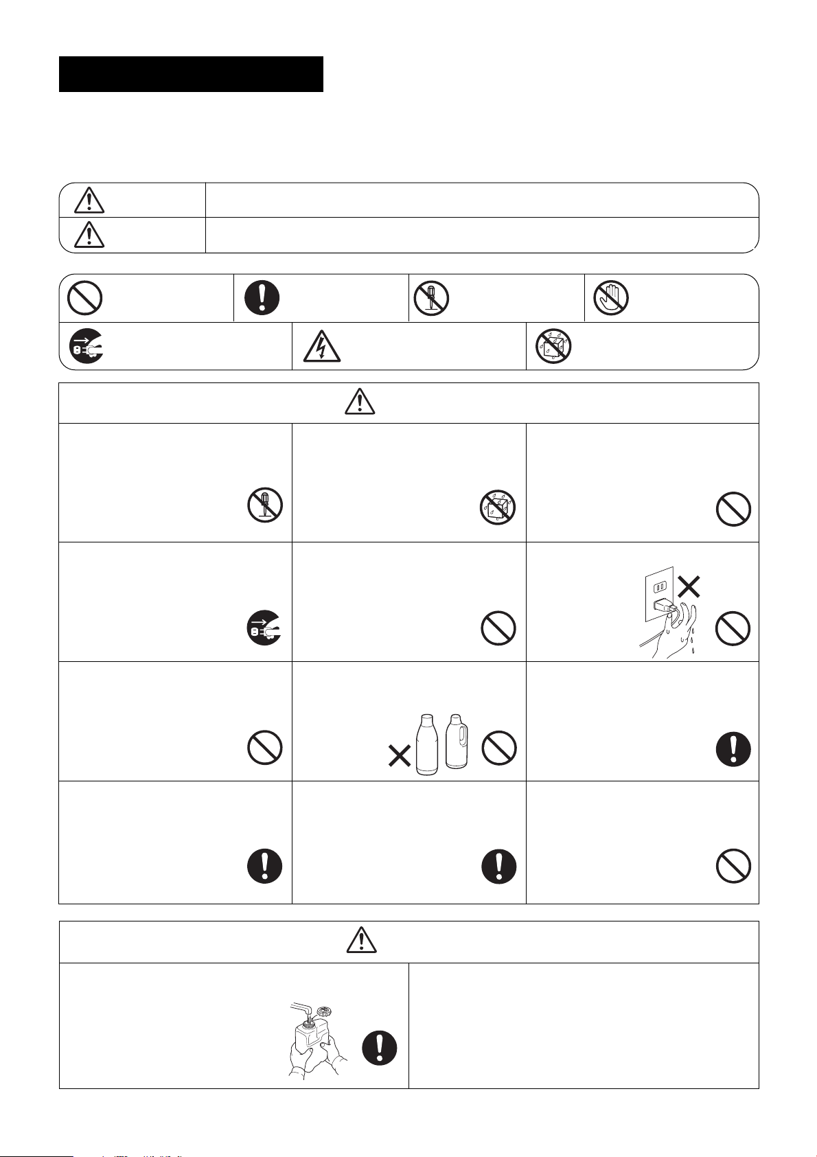
Sanyo VW-VF8AG Quick start guide

WARNING
– 1 –
WARNING
CAUTION
“Prohibited”: Indicates a
prohibited action.
“Required”: Indicates a
required action.
CAUTION
Safety Precautions
Be sure to read the following important safety information for safe and correct use of the product.
The items listed here represent important information related to safety. The indicators and their
meanings are as shown below.
Incorrect handling or use may result in death or serious injury to the user.
Incorrect handling or use may result in injury to the user, or in property damage.
“Do not disassemble”:
Indicates that
disassembly is prohibited.
“Do not touch”:
Indicates that contact
is prohibited.
“Unplug”: Indicates that the power
cord must be unplugged.
“Electric Shock Danger” (Located
on main unit): Indicates that there
is the danger of electric shock.
“Do not wet”: Indicates that contact
with water is prohibited.
Do not disassemble or modify.
Do not attempt to disassemble for repair or to
modify this system. Doing so may result in
fire, electric shock, or injury.
For repairs, consult with the
dealer where the product was
purchased.
Do not
disassemble
Unplug the power cord before
cleaning or servicing the system.
When cleaning or servicing the system, be
sure to first unplug the power cord.
Failure to do so may result in
electric shock or injury.
Unplug
Do not use with any power other
than 220 – 240 V AC power. Do
not plug multiple cords into the
same outlet.
Doing so may result in fire, electric
shock, or damage to the system.
Prohibited
Remove dirt or grim from the
power plug.
Regularly remove any dirt or grim from the
power plug.
If dirt or grim accumulates on the
power plug, humidity or other
factors may cause an insulation
failure, resulting in fire.
Required
Do not apply water.
Do not soak this unit in water or apply water
to it.
Doing so may result in a short circuit and
electric shock.
Do not wet
Do not damage the power cord.
Do not scratch, cut, modify, bend excessively,
pull on, twist, or otherwise damage the power
cord.
Damage to the power cord may
result in fire or electric shock.
Prohibited
Do not use chlorine-based or
acidic detergents when cleaning
the water tank, unit, or filters.
These detergents
may result in
deformation and
discoloration.
Prohibited
A leakage breaker is required.
Use a power source that includes a leakage
breaker.
Failure to do so may result in
electric shock or fire.
Required
Do not insert foreign objects.
Do not insert metal objects such as pins or
needles, or other foreign objects, into the
intake, outlet, or water tank installation port.
Doing so may result in injury due to
electric shock, or in abnormal
operation of the system.
Prohibited
Do not plug or unplug the power
cord with
wet hands.
Doing so may result
in electric shock.
Prohibited
Insert the power plug securely, all
the way to the base.
Do not use a plug that cannot be fully
inserted or that is damaged. Do not use a
loose power outlet.
Doing so may result in electric
shock or in fire caused by heating.
Required
Do not use insecticides or
aromatics.
Do not use insecticides, aromatics, or
mosquito coils while the unit is
operating.
Doing so can cause system
malfunction.
Prohibited
Acidic
Chlorine-
based
Fill the water tank with new water every day.
Rinse out the water tank every day and keep it clean. Then be sure to
refill it with tap water.
If you continue to use the tank without
cleaning it, sediment and water scale may
decrease the performance of the unit,
or may cause the growth of mold or
bacteria, resulting in odor.
Required
To relocate the unit or store it (when it will not be
used for two weeks or longer), request servicing
by the dealer.
06-289 Virus_Washer-TM 8/31/06 2:19 PM Page 1

– 2 –
Precautions
CAUTION
Important information
Do not place any containers that
contain liquid on top of the
system.
Doing so may result in system
malfunction.
Prohibited
Be sure to securely reinstall all
components after cleaning.
Using the unit without the water tank, filter, or
other component securely installed
may result in system malfunction.
Required
Install the system indoors, and
use in an environment between
5°C and 30°C.
In a particularly cold environment, the freeze-
prevention function may be
activated, and the unit may not
operate even when the power
switch is turned ON.
Required
Do not install in a location
exposed to dripping water.
Doing so may result in system malfunction.
Prohibited
Do not perform cleaning while the
system is operating.
Doing so may result in electric shock or
injury.
Prohibited
Grasp the power plug when
unplugging the power cord.
When unplugging the power cord, do not
grasp the cord. Instead, be sure to grasp the
power plug at the end of the cord
and pull out the plug. Unplugging
the cord incorrectly may result in
electric shock, short circuit, or fire.
Required
Do not use the system with the
filter removed.
Dust entering into the system may cause
system malfunction.
Required
Avoid installation in high
locations. Install in a flat and
stable location.
Observe this precaution in order to ensure
that the system functions correctly.
Failure to do so may result in the
unit tipping over due to earthquake
or contact by persons.
Required
Do not obstruct the outlet.
Do not obstruct the outlet with a curtain,
towel, or other item.
Doing so may result in system malfunction.
Prohibited
Do not place any items on the
unit.
Do not climb onto the unit.
Doing so may result in system
malfunction, or in the unit tipping
over.
Prohibited
Install in a location where there is
little humidity, cigarette smoke,
or other airborne substance.
Select a location for use which is free of humidity, dust,
cigarette smoke, incense smoke, oil smoke
(oil particles generated by food preparation),
salt, or ammonia. Failure to do so may result
in odors or in system malfunction.
Required
Secure space of 10 cm or more at
the left and right sides of the unit.
Also, allow servicing space of 100 cm or
more above and to the front of the unit.
Failure to do so may result in
system malfunction.
Required
Be sure to use normal tap
(drinking) water.
Never use water from a water purifier, water
from a water heater, alkali ion water, mineral
water, well water, seawater, or other types of
water. These types of water cannot be
electrolyzed and can cause the growth of
mold or bacteria, resulting in odor.
Do not use tap water in regions
where the concentration of
chlorine ions in the tap water is
low, or in regions where the
chlorine concentration is high.
In some regions, the quality of the tap water
prevents the use of this product. For details,
consult with a dealer.
Do not unplug the power cord,
even if the unit will not be used
for a while.
Even when the unit is stopped, cleaning
inside the system is performed automatically.
Check that there is water in the water tank,
and do not unplug the power cord.
Perform regular cleaning.
Follow the instructions under “Cleaning the
System,” in order to clean and maintain the
unit.
If the unit becomes especially dirty, mold may
grow, resulting in odor.
Do not direct the discharged air
directly onto walls or furniture.
Do not allow the discharged air to directly
contact walls or furniture.
It may damage the walls or furniture, resulting
in stains.
Be careful of freezing.
Freezing may result in system malfunction
and damage.
06-289 Virus_Washer-TM 8/31/06 2:19 PM Page 2

– 3 –
Model name Commercial Space Cleaning System (Floor-Mounted)
Product No.
Height
External
dimensions
Electrical
characteristics
Fan
Width
Depth
Product weight
Operating weight
Water tank capacity
Exterior color (Munsell number)
Power source
Power cord length
Operating current
Power consumption
Power factor
Model name Qty.
Rated airflow
Motor output (No. of poles)
Protective devices
Operating SW
Service temperature
Operating noise
Guide to water refill
Primary accessories
mm
mm
mm
kg
kg
L
–
–
–
–
–Filters
dB (A)
hrs/refill
–
°C
–
m
A
W
W
%
m3/min
VW-VF8AG
615
1,085
230
40
44 (whenwater tank isfull)
Approx. 4
Silky Shade (1 Y8.5 / 0.5)
Single-phase, 220 – 240 V, 50 / 60 Hz
Protective thermostat, fuse
Built-inunit control section
Long-life filter (intake side)
Protective net (outlet side)
Turbo: 45 / High: 38 / Standard: 38 *2
Turbo: Approx. 4 / High: Approx. 6 / Standard: Approx. 9 *3
Tip-over preventionchain, User’sManual, InstallationManual
5 – 30
Sirocco fan1
1.5 (No ground)
1.1 / 1.2
100 / 115
30 (4P)
91 / 96
Turbo: 8/ High: 5 / Standard: 3*1
Specifications
1. Product Specifications
When the fan speed is standard, the fan operates intermittently.
*1: The rated airflow for the standard fan speed is the average airflow during intermittent operation.
*2: The operating noise for the standard fan speed is the operating noise when the fan is operating during
intermittent operation.
*3: The guide to water refill is the number of hours at a room temperature of 20°C and 35%relative humidity.
* The operating noise conforms to JIS standards, and was measured in an anechoic chamber. Therefore it is the
value at a position 1 m in front of the unit and a height of 1 m. When the unit is actually installed, ambient noise
and noise reflection ordinarily result in noise than the value indicated here.
06-289 Virus_Washer-TM 8/31/06 2:19 PM Page 3

– 4 –
–30 –25 –20 –15 –5–10 0 5 10 15 20 25 303540455055606570
0
5
10
15
20
25
30
35
40
45
50
55
60
65
70
Resistance [kΩ]
Temperature [°C]
–20 –15 –10 –5 0 1051520
0
10
5
15
20
30
25
35
40
Resistance [kΩ]
Temperature [°C]
20 30405060
0
2
1
3
4
6
5
7
8
Resistance [kΩ]
Temperature [°C]
2. Part Specifications
GFan motor coil resistance
GThermistor characteristics
Model name KUE4T-31CPZ
Blue – Brown 29.91
Resistance Purple – Blue 9.00
(ΩΩ) Yellow – Purple 5.81
Yellow – Pink 14.96
Intake temperature sensor
Electrolyzing unit water temperature sensor
3. Control Specifications
Microcomputer control: Settings: Fan speed select (turbo, high, standard)
Service functions: Alarm display
06-289 Virus_Washer-TM 8/31/06 2:19 PM Page 4

– 5 –
65
51
78
3
4
65312 4
65312 4
12
13
13
13
13
1
1
5
1
3
5
312 13
13+
+
1313
13
13
131312 12
3
1
P
S
23
456
654
123
123
3
12
546
531
FAN L H HH
RC
7
9
1
5
456
78
FMI
SCHEMATIC DIAGRAM
FMI
2X
2X
DP
TH1
TH2
ELEC-
TRODE
3X
RY006
3X
AC IN-1
TR3
CR2
1ø 230V
1ø 230V
TERMINAL
PLATE (3P)
L1 N
RED
BRN
WHT
WHT
WHT
BLK
WHT
WHT
BRN
BRN
WHT
WHT
BRN
BRN
BRN
RED
ORG
RED
YEL
WHT
BLK
BLU
ORG
RED
YEL
RED
BRN
WHT
BLK
BLU
ORG
RED
WHT BRN
BRN
BRN
GRY
GRY
BLK
BLK
BLK
BLK
BLK
BLK
BLK
BLK
GRY
GRY
PNK PNK
YEL
VLT
BLU
YEL
VLT
BLU
RED
RED
ORG
ORG
TR3
TR2
TR1
TR1
AC 100V
AC 100V
TR2 POW
CR1
CS
IND
SYMBOLS
FMI INDOOR FAN MOTOR
8FA-2-5250-039-00-0
49FI INDOOR FAN MOTOR
RC RUNNING CAPACITOR
TR1
TR2 POWER TRANSFORMER
TR3
FS2 FLOAT SWITCH
DP DRAIN PUMP
TH1 THERMISTOR (WATER TEMP)
TH2 ROOM THERMISTOR
CSCONTROL SWITCH
CR1 INDOOR CONTROLLER
CR2 FILTER CONTROLLER
POW POWER CONTROLLER
IND IND LAMP ASSY
TERMINAL PLATE
CONNECTOR
TERMINAL
F1, F2 FUSE
2X, 3X
RY006 AUXILIARY RELAY
ELEC-
TRODE ELECTRODE
DESCRIPTION
IND
LAMP
WTH
RC
TRANS-S
TRANS-P
TA
DP
FS2
IC-Q
24VDEN
TRANS-S
TRANS-P
IC-Q
24VDEN
FS2
DENKYOKU
FS2
DF
TH1 TH2
LN
L
N
S
RF2
11
7
1
2
1
3
6
5
4
3
2
1
1
2
1
2
1
2
1
3
1
3
1
3
1
3
3
1
2
1
3
1
3
1
3
5
5
3
1
4
5
6
1
2
3
4
5
6
3
1
49FI
8
3
AC IN
RF1 T20
S
L1 N
1
3
BRN
BRN
AC
100V
AC
100V
AC
100V
CONNECTOR
6P (WHT)
CONNECTOR
8P (WHT)
AC
100V
BRN
BRN
BRN
BRN GRN/YEL
GRN/YEL
GRN/YEL
GRN/YEL
GRN/YEL
AC_IN
(
BLK
)
AC IN
(
BLK
)
AC IN-1
(
BLK
)
IC-Q
(
WHT
)
(
GRN
)
24VDEN
(
WHT
)
IC-Q
(
WHT
)
IND LAMP
(
RED
)
DENKYOKU E
+
E
RC
(
BLU
)
T20
(
GRY
)
FS2
(
YEL
)
DP
(
BUL
)
WTH
(
RED
)
TA
(
YEL
)
TRANS-P1
(
YEL
)
TRANS-S1
(
WHT
)
24VDEN
(
GRN
)
TRANS-S
(
WHT
)
951 37
FAN
(
WHT
)
AC_OUT
(
WHT
)
AC_IN
AC_OUT
E
CS
RS
FILTER
CONTROLLER
POWER
CONTROLLER
CONTROLLER
VW-VF8AG
ELECTRIC WIRING DIAGRAM
IND
ELECTRODE
Circuit Diagram
06-289 Virus_Washer-TM 8/31/06 2:19 PM Page 5
Table of contents
Other Sanyo Air Cleaner manuals