Sanyo VSP-CB10 User manual

INSTRUCTION MANUAL VSP-CB10
COAX-SSP Converter English GB
COAX-SSP-Umwandler Deutsch D
Convertisseur COAX-SSP Français F
Convertidor COAX-SSP Español E
Convertitore COAX-SSP Italiano I
Before installing and using this unit, please read this manual carefully. Be sure to keep it handy for
later reference.
This unit converts coaxial signals to SSP signals, and also SSP signals to coaxial signals.
L8ZBA/XE (VSP-CB10) GB 2002, 1, 8

Precautions
In case of problems
Do not use the unit if smoke or a strange odor
comes from the unit, or if it seems not to function
correctly. Disconnect the power cord immediately,
and consult your dealer (or a Sanyo Authorized
Service Centre).
Do not open or modify
Do not open the ca inet, as it may e dangerous
and cause damage to the unit. For internal settings
and repairs, consult your dealer (or a Sanyo
Authorized Service Centre).
Do not put objects inside the unit
Make sure that no metal o jects or flamma le
su stance get inside the unit. If used with a foreign
o ject inside, it could cause a fire, short-circuits or
damages.
If water or other liquid gets inside the unit,
disconnect the power cord immediately, and
consult your dealer (or a Sanyo Authorized Service
Centre). Be careful to protect the unit from rain,
seawater, etc.
Be careful when handling the unit
To prevent damage, do not drop the unit or su ject
it to strong shock or vi ration.
Install away from electric or magnetic fields
If installed close to a TV, radio transmitter, magnet,
electric motor, transformer, or audio speakers, the
magnetic field they generate may distort the image.
Protect from humidity and dust
To prevent damage to the unit, do not install it
where there is greasy smoke or steam, where the
dampness may get too high, or where there is a lot
of dust.
Protect from high temperatures
Do not install close to stoves or other heat
generating devices, such as spotlights, or where the
unit could e su ject to direct sunlight, as that
could cause deformation, discoloration or other
damage.
Be careful when installing close to the ceiling in a
kitchen or oiler room, as the temperature may rise
to high levels.
Install where the temperature range will stay
etween 5°C and 40°C. (no condensation)
Cleaning
●Dirt can e removed from the ca inet y wiping
it with a soft cloth. To remove stains, wipe with
a soft cloth moistened with a neutral detergent
solution and wrung dry, then wipe dry with a
dry soft cloth.
●Do not use solvents, thinner or other chemical
product on the ca inet, as that may cause
deformation and paint peeling. Before using a
chemical cloth, make sure to read all
accompanying instructions. Make sure that no
plastic or ru er material comes in contact with
the ca inet for a long period of time, as that
may cause damage or paint peeling.
Contents
Main features. . . . . . . . . . . . . . . . . . . 1
Part names . . . . . . . . . . . . . . . . . . . . . 2
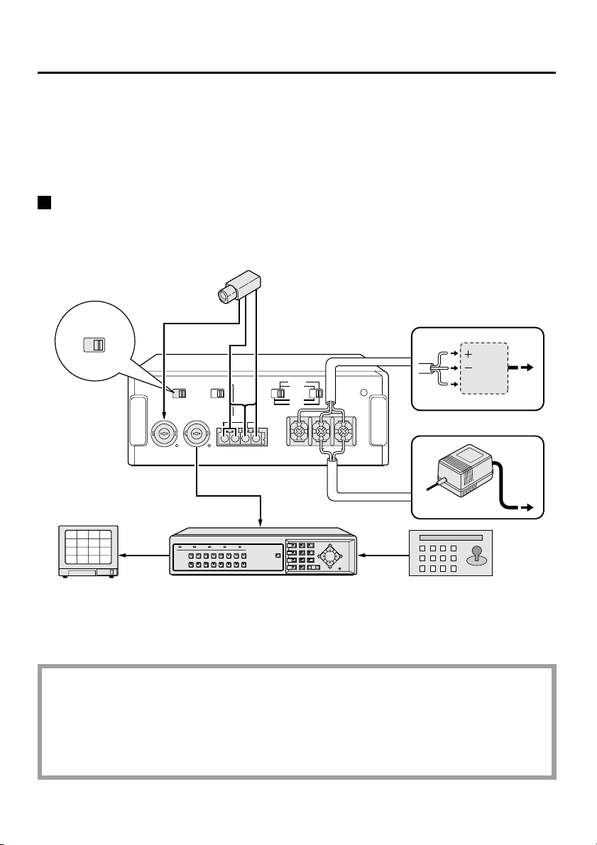
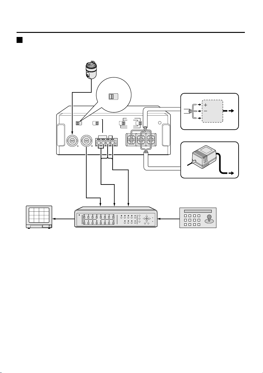
Connections . . . . . . . . . . . . . . . . . . . .
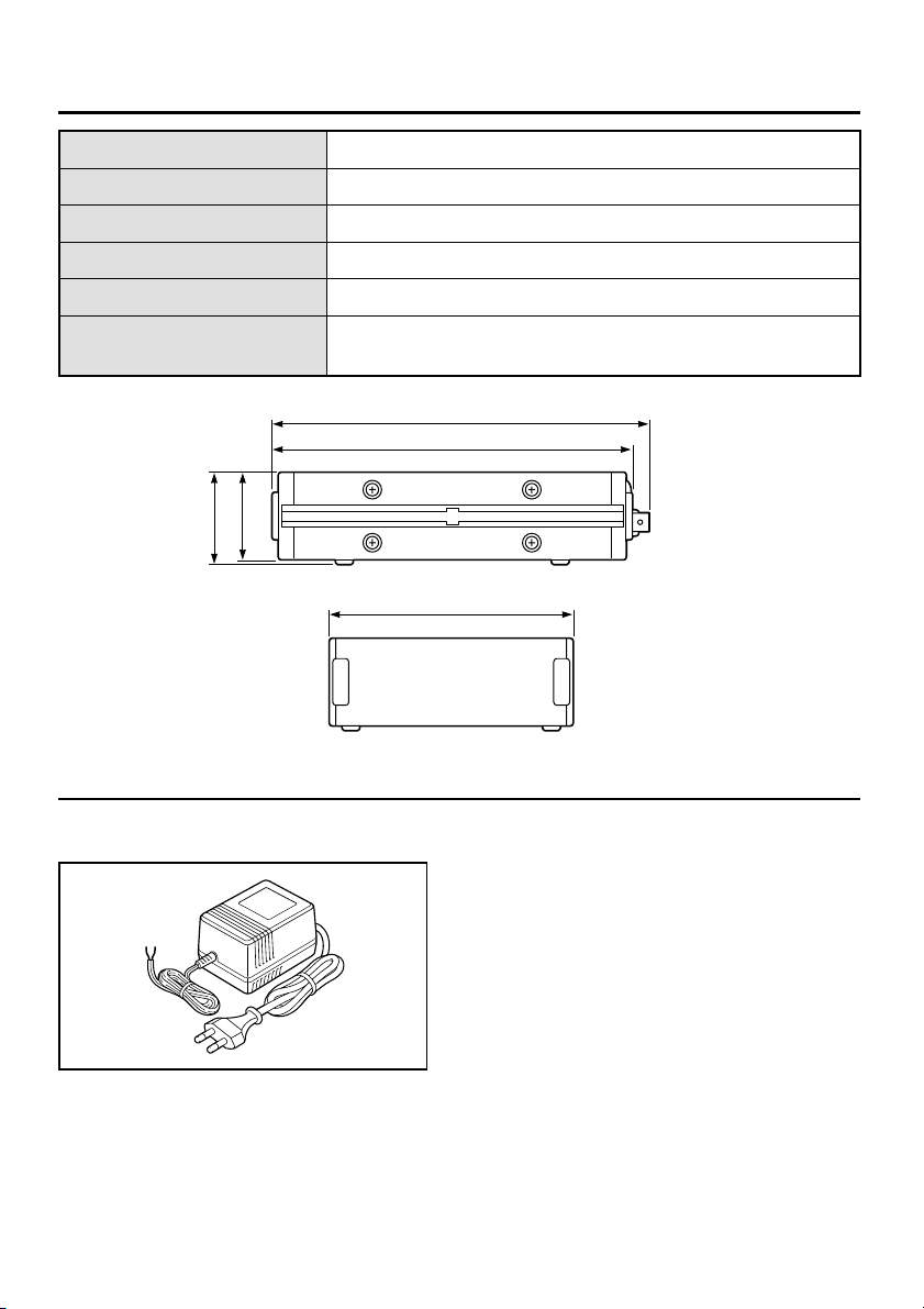
Specifications . . . . . . . . . . . . . . . . . . . 6
Main features
●Can convert SSP (RS-485) signals to coaxial
signals.
●Can convert coaxial signals to SSP (RS-485)
signals.
●Can change alarm signals etween multiplex and
separate signals y switch operation.
●The grooves at oth sides of the unit can e
used to install the unit to a structure such as a
rack.
English – 1 –

Part names
Be sure to turn off the power efore changing the settings for any of the setting switches (1, 2 and 3).
If you change a switch setting while the power is still turned on, the setting may not change correctly.
1Control signal switch (CONTROL SIGNAL)
●Set to “MIX” to convert SSP
(RS-485) and video signals to
coaxial signals.
●Set to “SEPA” to convert
coaxial signals to SSP (RS-485)
and video signals.
2Termination switch (TERMINATE)
When multiple units are
connected together, set the
switch for the first and last unit in
the series to “ON”.
3Communication speed select switches
Move the left and right switches to set the
communication speed. Set so that the speed matches
the speed of other connected equipment.
4Power indicator (POWER)
Illuminates when the unit’s power is turned on.
5Video input terminal (CAMERA IN)
Connect a camera to this terminal.
(BNC termination)
6Video output terminal (VIDEO OUT)
This terminal is for camera output.
(BNC termination)
Connect a multiplexer or other similar device.
7RS-485 control terminals (RS485)
Connect to the RS-485 control terminals of a
multiplexer or system controller using twisted-pair
ca les (sold separately).
Connect signal A to signal A and signal B to signal B.
8Alarm terminals (ALARM)
Connect the alarm signal from a multiplexer or camera
to these terminals.
The C terminal is used for oth the RS-485 ground and
the AL ground. Be sure to connect to the C terminal
also when making an AL connection.
This terminal is used for alarm output when the control
signal switch is set to MIX, and alarm input when the
control signal switch is set to SEPA.
9Power input terminals
Connect a 24 V AC or 12 V DC.
19200
9600
2400
24V AC
12V DC
GND
A
RS485
BCAL
ALARM
TERMINATECONTROL SIGNAL
ONOFF
VIDEO
OUT
CAMERA
IN
SEPAMIX
POWER
4800
bps
CLASS 2 WIRING
1
5678 9
243
CONTROL SIGNAL
MIX SEPA
CONTROL SIGNAL
MIX SEPA
TERMINATE
OFF ON
Setting to 2400 bps
Setting to 9600 bps
Setting to 4800 bps
Setting to 19200 bps
bps
4800
2400
9600
19200
bps
4800
2400
9600
19200
bps
4800
2400
9600
19200
bps
4800
2400
9600
19200
A
RS485
BCAL
ALARM
Push and insert cables
Twisted-pair cable
Ground
To signal A
To signal B
–2 –English

Connections
Note:
●Up to two COAX-SSP converters can e connected when making an SSP (RS-485) connection. If more than
two units are connected together, delays may occur in SSP (RS-485) signal response and communication
may not proceed correctly.
●After connecting, change the communication speed settings, alarm settings and address settings for the
camera or multiplexer to match the settings for other peripheral equipment. If the settings are not correct,
the system may not operate correctly.
Operating a SSP (RS-485) signal-type camera using a coaxial-type
multiplexer
This unit can convert coaxial signals into SSP (RS-485) signals, so that an SSP (RS-485) signal-type camera can
e operated using a coaxial-type multiplexer.
19200
9600
2400
24V AC
12V DC
GND
A
RS485
BCAL
ALARM
TERMINATECONTROL SIGNAL
ONOFF
VIDEO
OUT
CAMERA
IN
SEPAMIX
POWER
4800
bps
CLASS 2 WIRING
CONTROL SIGNAL
SEPAMIX
SSP (RS-485)
SSP
(RS-485)
6
2
10
14
5
1
9
13
7
3
11
15
8
4
12
16
System controller
(sold separately)
Camera unit
(sold separately)
TV monitor
(sold separately)
VIDEO IN
connector
VIDEO IN
connector
Coaxial-type multiplexer (sold separately)
ALARM IN
connector
or
GND
This installation should be made by qualified service person and should
conform to all local codes.
WARNING: To reduce the risk of fire or electric shock, do not expose this
appliance to rain or moisture.
English –3 –

Connections
Operating a coaxial-type camera using a system controller
This unit can convert SSP (RS-485) signals into coaxial signals, so that a coaxial-type camera can e operated
using a system controller.
19200
9600
2400
24V AC
12V DC
GND
A
RS485
BCAL
ALARM
TERMINATECONTROL SIGNAL
ONOFF
VIDEO
OUT
CAMERA
IN
SEPAMIX
POWER
4800
bps
CLASS 2 WIRING
CONTROL SIGNAL
SEPAMIX
6
2
10
14
5
1
9
13
7
3
11
15
8
4
12
16
Dome-type camera unit (PTZ)
(sold separately)
VIDEO IN
connector
VIDEO IN
connector
ALARM IN
connector
SSP
(RS-485)
SSP
(RS-485)
System controller
(sold separately)
TV monitor
(sold separately) SSP (RS-485) signal-type multiplexer
(sold separately)
or
GND
–4 –English

Connections
The COAX-SSP converter can e secured y using olts (M4) or nuts (M4) as descri ed elow.
Installation example 1 (using bolts)
Insert olts into each of the two grooves on oth sides of the converter.
Installation example 2 (using nuts)
Insert nuts into each of the two grooves on oth sides of the converter.
However, if using threaded fasteners such as olts to secure the converter, select bolts which will not go
any more than 5 mm past the surface of the converter. If longer olts are used, they may damage the
converter.
Note: Parts such as the olts and nuts required a ove are not supplied with the converter and must e
purchased separately.
1
2
Bolt (M4)
1
2
Nut (M4)
English –5 –

Specifications
Camera input BNC termination
Camera output BNC termination
Operating environment Temperature: –10°C – 50° C
Dimensions 123 (W) x 189.8 (D) x 46 (H) mm
Weight Approx. 600 g
Power supply 24 V AC/12 – 15 V DC: 100 mA 1.3 W
LED illuminates when power supplied
Option
112 V DC power supply (VCA- 5E)
1
189.8
182
123
44
46
(Unit: mm)
–6 –English

1AC6P1P2465--
L8ZBA/XE (0102KP-CZ)
SANYO Electric Co., Ltd.
Printed in Japan
L8ZBA/XE (VSP-CB10) GB 2002, 1, 8
Table of contents
Other Sanyo Media Converter manuals
Popular Media Converter manuals by other brands

AXIOMTEK
AXIOMTEK icon-101CU Quick installation guide

MSB Technology
MSB Technology Nelson LINK DAC III user manual

Lenz
Lenz 10133 quick guide

Reliance electric
Reliance electric 1203-USB instruction manual

Curtis
Curtis RCD898 Specification sheet

ZyXEL Communications
ZyXEL Communications MC-100FX-SC2 user guide