Merging Horus User manual
Horus User Manual
Merging Technologies
Le Verney 4, CH-1070 Puidoux Switzerland
www.merging.com/horus T : +41 21 946 04 44 F : +41 21 946 04 45
HorusUserManual
Revision 0.3

Horus User Manual
www.merging.com/horus Page 2
Contents
INTRODUCTION TO HORUS....................................................................................................................8
........................9
......................11
......................17
......................22
..........................23
......................24
..........................24
..........................25
..........................25
......................28
......................30
......................31
..........................31
..........................32
..........................32
..........................33
..........................34
..........................34
..........................34
..........................35
..........................37
..........................38
..........................39
..........................40
..........................40
..........................41
..........................42
..........................42
..........................43
.......................44
Installing and accessing the Horus Control interface remotely.........................................................................44
HorusStandaloneConverter: .......................................................................................................................................47
HorusConverterwithPyramixV8&Ravenna......................................................................................................49
TotalRedundancy .............................................................................................................................................................50
HoruswithRavennaPyramixV8Native:Live–MobileRecording..............................................................52
HORUS TROUBLESHOOTING...............................................................................................................57
HORUS HARDWARE........................................................................................................
HORUS OPT ..IONAL CARDS...........................................................................................
HORUS CABLES ..............................................................................................................
HORUS KE ..Y FEATURES ...................................................
Key Specification ..
............................................
s...................................................................................................................................
Installing additional Horus I/O Module ..........................................................................
nal Horus MADI Extension Module (MADM or MADS) ...........................
Before you start .........................................................................................................................................
oInstalling additi ...
..Before you get started ..........................................................................................................................
..Installing the Merging PCIe Ethernet Controller Card NET-MSC-GBEX1...............
..HORUS POWER ON.......................................................................................................
..HORUS TOUCH SCREEN CONTROL INTERFACE......................................................
HorusMenuHierarchy........................................................................................................................
..
..
MainHomeScreen ................................................................................................................................
..MonitorMenu..........................................................................................................................................
..IO&SyncMenu ......................................................................................................................................
..
REFSMenu(I/O&Sync).....................................................................................................................
..
..
MetersMenu............................................................................................................................................
PreAmpMenu .........................................................................................................................................
..SETUPMENU...........................................................................................................................................
..FormatsMenu(Setup).........................................................................................................................
ModulesMenu(Setup) ........................................................................................................................
Modules:MADISub‐Menu ...................................................................................................................
..
Modules:A/D‐AESSub‐Menu.........................................................................................................
..
..
Modules:D/ASub‐Menu ....................................................................................................................
..
..
Modules:Loopback...............................................................................................................................
RoutingMenu(Setup) .........................................................................................................................
Routing:Configuration..........................................................................................................................
NetworkMenu(Setup)..........................................................................................................................
HORUS WEB CONTROL ACCESS.................................................................................

Horus User Manual
www.merging.com/horus Page 3
IMPORTANT SAFETY AND
INSTALLATION INSTRUCTION
S
INSTRUCTIONS
G – when using electric products, basic precautions should be followed, including the following:
ols before using
st be grounded. If it should malfunction or breakdown, grounding provides a path of
least resistance or electric current to reduce the risk of electric shock. This product is equipped with a
he plug must be
ce with all local
DANGER – Improper connection of the equipment-grounding can result in a risk of electric shock. Do
per outlet installed
adapter that defeats the function of the equipment-grounding
ck with a qualified
en sink, in a wet
the manufacture.
5. This product, either alone or in combination with an amplifier and speakers or headphones, may be
t operate at a high
vel that is uncomfortable. If you experience any hearing loss or ringing in the
cation or position does not interfere with its proper
he product should be located away from heat sources such as radiators, heat registers, or other
8. The product should be connected to a power supply only of the type described in the operating
9. The power-supply cord of the product should be unplugged from the outlet when left unused for a
long period of time. When unplugging the power supply, do not pull on the cord, but grasp it by the
plug.
10. Care should be taken so that objects do not fall and liquids are not spilled into the enclosure through
openings.
11. The product should be serviced by qualified service personnel when: A. The power supply cord or
SAVE THESE INSTRUCTION
PERTAINING TO RISK OF FIRE, ELECTRIC
SHOCK, OR INJURY TO PERSONS
WARNIN
1. Read all of the safety and installations instructions and explanation of graphic symb
the product.
2. The product mu
power supply cord having an equipment-grounding conductor and a grounding plug. T
plugged into an appropriate outlet which is properly installed and grounded in accordan
codes and ordinances.
not modify the plug provided with the product – if it will not fit the outlet have a pro
by a qualified electrician. Do not use an
conductor. If you are in doubt as to whether the product is properly grounded, che
serviceman or electrician.
3. Do not use this product near water – for example, near a bathtub, washbowl, kitch
basement, or near a swimming pool, or the like.
4. This product should only be used with a stand or cart that is recommended by
capable of producing sound levels that could cause permanent hearing loss. Do no
volume level or at a le
ears, you should consult an audiologist.
6. The product should be located so that its lo
ventilation.
7. T
products that produce heat.
instructions or as marked on the product.

Horus User Manual
www.merging.com/horus Page 4
plug has been damaged. Objects have fallen, or liquid has spilled into the product, or C. The pr
has been exposed to rain, or D. The product does not appear to be operating normally oduct
or exhibits a
damaged.
maintenance instructions.
t in a position
r roll anything over cords of any type. Do not allow the
product to rest on or be installed over cords of any type. Improper installations of this type create the
possibility of a fire hazard and/or personal injury.
marked change in performance, or E. The product has been dropped, or the enclosure
12. Do not attempt to service the product beyond that described in the user
All other servicing should be referred to qualified service personnel.
13. WARNING - Do not place objects on the power supply cord, or place the produc
where anyone could trip over, walk on, o
The lightning flash with arrowhead symbol, within an equilateral triangle, is
s voltage"
stitute a risk
The exclamation point within an equilateral triangle is intended to alert the user
to the presence of important operating and maintenance (servicing) instructions
in the literature accompanying the product.
intended to alert the user to the presence of uninsulated "dangerou
within the product's enclosure that may be of sufficient magnitude to con
of electric shock to persons.
No part of this documentation may reproduced in any form whatsoever or be stored i
system without prior written permission of the copyright owners.
This documentatio
n any data retrieval
n is supplied on an as-is basis. Information contained within this documentation is
owners.
mbedded
software, its quality, performance, merchantability or fitness for a particular purpose. The software is
supplied “as is” you, the purchaser, are assuming the entire risk of the results of using this Merging
In no circumstances will Merging Technologies, its owners, directors, officers, employees or agents be
liable to you for any consequential, incidental or indirect loss or damages including loss of time, loss of
business, loss of profits, loss of data or similar resulting from the use of or inability to use the Merging
Technologies hardware and or software or for any defect in the hardware software or documentation.
© Copyright Merging Technologies Inc. 2012. All rights reserved.
subject to change at any time without notice and must not be relied upon.
All company and product names are ™ or Registered Trademarks ® of their respective
Windows 7 is a trademark of Microsoft Corporation.
Merging Technologies makes no warranties express or implied regarding the Horus e
Technologies software.

Horus User Manual
www.merging.com/horus Page 5
IMPORTANT NOTICE:
Please read the following information very carefully before attempting any installation. Failu
the precise instructions may r
re to comply with
esult in damage to your Merging hardware. Please read this entire section of the
stallation.
ains delicate electronic components that can be damaged or even destroyed
. Take all necessary precautions not to discharge static electricity when
Converter is designed and tested to meet the standards and regulations listed in
liance
nts:
EN 60 950 (European Union).
nal).
he following EMC regulations:
Conducted Emissions (USA).
ated and Conducted Emissions (International).
uation and Flicker).
ing two conditions: (1)
rence received,
und to comply with the limits for a Class A digital device, pursuant to
reasonable protection against harmful
dio frequency
n a particular
n, which can be
ined by turning the equipment off and on, the user is encouraged to try to correct the interference by
ceiver is connected.
Consult the dealer or an experienced radio/TV technician for help.
Any changes or modifications not expressly approved by the grantee of this device could void the user’s
authority to operate the equipment. The customer is responsible for ensuring compliance of the modified
product.
Only peripherals (computer input/output devices, Ethernet switches, terminals, printers, etc.) that comply with
FCC Class B limits may be attached to this computer product. Operation with noncompliant peripherals is
likely to result in interference to radio and TV reception.
All cables used to connect to peripherals must be shielded and grounded. Operation with cables, connected
to peripherals that are not shielded and grounded, may result in interference to radio and TV reception.
manual carefully before in
STATIC DANGER NOTICE:
Please note that the Horus cont
when exposed to static electricity
touching any of the Horus connectors.
Product Regulatory Compliance
The Merging Horus Network
the following sections.
Product Safety Comp
Horus complies with the following safety requireme
UL 1950 – CSA 950 (US/Canada).
IEC 60 950 (Internatio
CE – Low Voltage Directive (73/23/EEC) (European Limits).
EMKO-TSE (74-SEC) 207/94 (Nordics).
Product EMC Compliance
The system has been tested and verified to comply with t
FCC (Class A Verification) – Radiated and
CISPR 22, 3rd Edition (Class A) – Radi
EN45022 (Class A) – Radiated and Conducted Emissions (European Union).
EN45024 (Immunity) (European Union).
EN6100-3-2 & -3 (Power Harmonics and Fluct
CE – EMC Directive (89/33/EEC) (European Union).
Electromagnetic Compatibility Notices
This device complies with Part 15 of the FCC Rules. Operation is subject to the follow
this device may not cause harmful interference and (2), this device must accept any interfe
including interference that may cause undesired operation.
This equipment has been tested and fo
Part 15 of the FCC Rules. These limits are designed to provide
interference in a residential installation. This equipment generates, uses, and can radiate ra
ructions, may cause harmful interference toenergy and, if not installed and used in accordance with the inst
radio communications. However, there is no guarantee that interference will not occur i
installation. If this equipment does cause harmful interference to radio or television receptio
determ
one or more of the following measures:
Reorient or relocate the receiving antenna.
Increase the separation between the equipment and the receiver.
Connect the equipment to an outlet on a circuit other than the one to which the re

Horus User Manual
www.merging.com/horus Page 6
Environmental Limits
ice Environment
its
es C with the maximum rate of change not to exceed 10
ure 45 degrees C) in a typical
office ambient temperature (18-25 degrees C)
(with 11-millisecond duration).
Package Shock Operational after a free fall, 18 – 24 inch depending on the weight.
ESD 15kV per Merging Environmental Test Specification
System Off
Parameter Lim
Operating Temperature +5 degrees C to +45 degre
degrees C per hour.
Non-Operating Temperature -40 degrees C to +70 degrees C
Non-Operating Humidity 95%, non-condensing @ 30 degrees C
mperatAcoustic noise less than 20 dBA (Cooling Mode set to Low, internal te
Operating Shock No errors with a half sine wave shock of 2G

Horus User Manual
www.merging.com/horus Page 7
Horus Warranty Information
one year from the
rchaser.
, Inc. will repair or
limited warranty,
e product failure.
the product to the
. If the consumer is not
t a further repair, or
cident, physical
ure to fire, water or excessive changes in the climate or temperature, or operation
outside maximum rating. (2) Products on which warranty stickers or product serial numbers have been
illegible. (3) The cost of installations, removal or reinstallation. (4) Damages
ing Merging
nal Office:
ies S.A.
CH-1070 Puidoux
itzerland
+41 21 946 0445
ent Audio)
United States of America
Phone: +1 (207) 773 2424
Fax: +1 (207) 773 2422
For all documentation inquiries or suggestions for improvement:
This product is warranted to be free of defects in materials and workmanship for a period of
date of purchase. Merging Technologies, Inc. extends this Limited Warranty to the original pu
In the event of a defect or failure to confirm to this Limited warranty, Merging Technologies
replace the product without charge within sixty (60) days. In order to make a claim under this
the purchaser must notify Merging Technologies, Inc. or their representative in writing, of th
In this limited warranty the customer must upon Merging Technologies, Inc. request, return
place of purchase, or other local designation, for the necessary repairs to be performed
satisfied with the repair, Merging Technologies, Inc. will have the option to either attemp
refund the purchase price.
This warranty does not cover: (1) Products which have been subject to misuse, abuse, ac
damage, neglect, expos
removed, altered or rendered
caused to any other products.
Contact
Internatio
Merging Technolog
Le Verney 4
Sw
1 946 0444Phone: +41 2
Fax:
USA:
Merging USA (Independ
43 Deerfield Road
Portland,
ME 04101-1805
www.merging.com
© 2012 All rights reserved. Merging Technologies and Horus are registered Trademarks of Merging
technologies SA.
Product features and specifications are subject to change without notice.
Merging Technologies SA shall not be liable for technical or editorial errors contained herein, nor for incidental
or consequential damages resulting from the furnishing, performance or use of this manual.

Horus User Manual
www.merging.com/horus Page 8
INTRODUCTION TO HORUS
Modular by Design
Horus was designed to give its users an amazing amount of Audio I/O channels, over all th
deployed formats, while offering an unprecedented level of quality in such a small form fac
Providing as standard 64 channels of MADI and 24 channel of AES- EBU I/O, you may choose
Analog I/O optional modules and one additional MADI extension module to bring the total MADI capacity to
128 chan
e most commonly
tor.
to add up to 6
nels and thereby create the ultimate audio interface for your studio, whatever the size. Once the
Horus is fully loaded with option cards, it is capable of achieving an astonishing 176 inputs and 178 outputs @
d 2 more output channels than input channels, including the Stereo Headphone
s been designed so that any input can be routed to any number of outputs as required…
uchscreen and by remote
r studio.
sers, Horus has been meticulously designed in order to keep power
dHorus running all channels of phantom power will only
han your kitchen lights.
1FS
XD/DSD256)
to any combination of outputs
peration... AND
er all I/O via the network
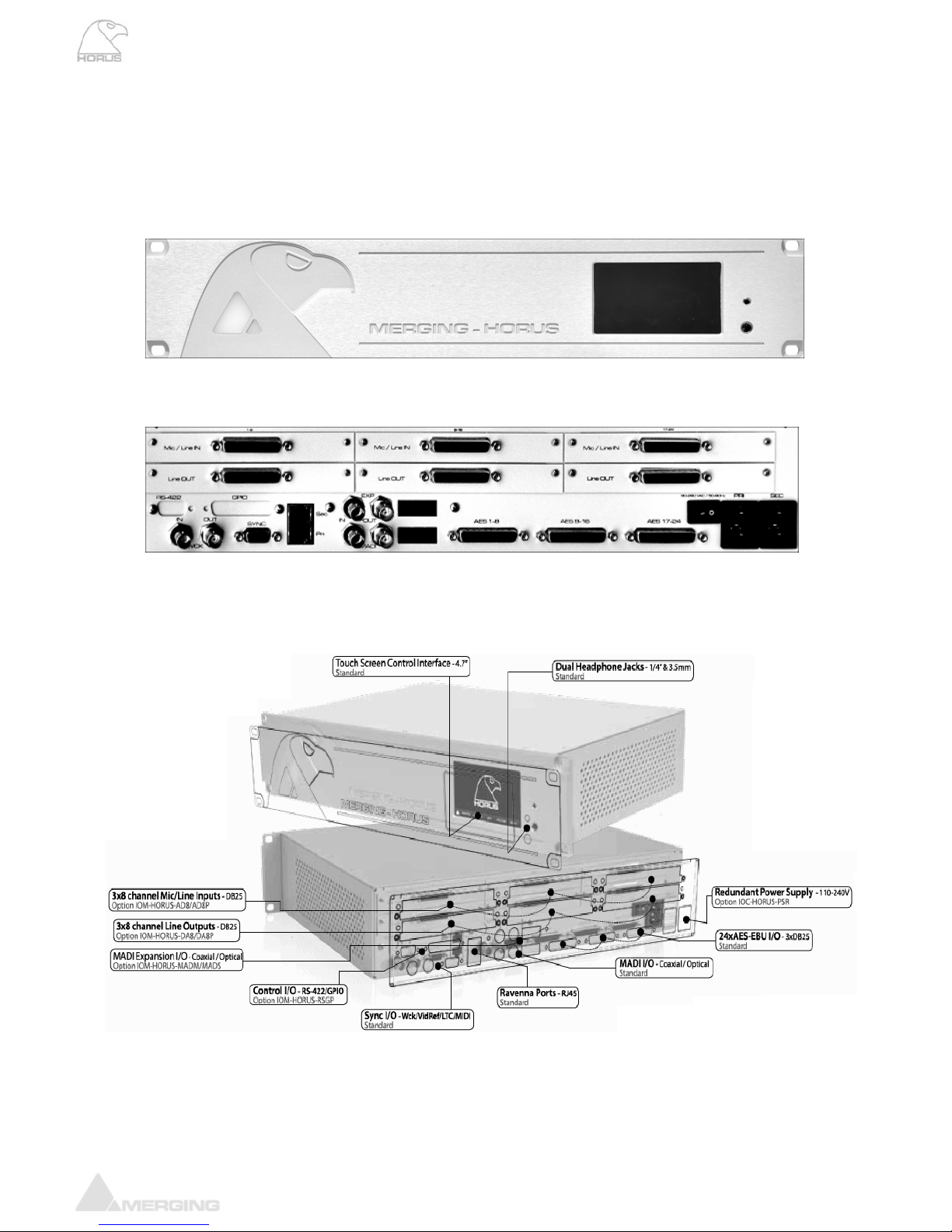
• Front panel touch screen for local access
• Modular design for analog and additional Digital I/O
The Horus has been designed so that the MADI, AES and Analog modules can all feed into or take their sources
gle CAT5e or
nection on the Horus allows for not only audio, but also control and sync information to flow
er the same network
uration and entire
are already in place, Ravenna
subnets can slip right into place with no additional outlay. In laymen’s terms, this means that you can connect
your Horus to a properly configured network exactly as you would your PC or Mac, with no additional
technology required.
Ravenna is a “mission critical” protocol, meaning that is has been designed to ensure immensely low jitter
rates and latencies (sub-millisecond) and ensures that every single sample gets to where it needs to go
without fail. Horus also provides a secondary, redundant Ravenna connection allowing for uninterrupted use,
even when a network connection fails.
Refer to the Ravenna User Guide and the MassCore-Ravenna Configuration Guide for more details
1FS There are indee
Monitoring.
Route Signal Anywhere
Horus ha
simultaneously. With comprehensive routing pages accessible both locally on the to
access using a standard web browser, Horus is the answer to signal flow management in you
Green Built
For environmentally-conscious u
consumption at an incredible minimum. A fully loade
draw about 60W, making it more affordable to run t
HORUS Key Features
• Up to176 inputs and 178 outputs @
• Works from 44.1 kHz to 192 kHz (Premium up to D
• Signal routing from any input
• Works as MADI/AES AD/DA for “standard” o
• Works in Ravenna mode to deliv
• Front panel Stereo Headphone monitoring
• Browser-based remote access using any web enabled device
• Dual redundant power supply option
• Near-zero latency from in to out (<1ms)
Ravenna
from the network over Ravenna streams, providing up to 176 channels of I/O @ 1FS over a sin
CAT6 cable to any other Ravenna devices on the network.
The Ravenna con
through as well. Send Timecodes, Wordclock and even GPIO directly to the Horus unit ov
as your audio. The Ravenna port even provides for remote control access to the config
routing of the unit itself! Support for: RS-422/LTC/MIDI/GPIO/Video Ref/WCK
Ravenna is a layer 3 IP based protocol. In environments where existing networks
Horus User Manual
HORUS HARDWARE
FRONT PANEL
BACK PANEL
HORUS UNIT DESCRIPTION
Page 9
www.merging.com/horus

Horus User Manual
www.merging.com/horus Page 10
HORUS BASE UNIT
pecif ation
ed Aluminum
moun ng) 48 mm
V –63 Hz
Power Consumption (Max) < 60 Watts
on 2 pixels
balan ed) Load = 300 Ohms +15 dBu
Ω
kHz) @ -2 dBFS < -100 dB (0.001 %)
lled) 0 d to +12 dB
1dB / ±0.05 dB
“Sy c” Cab e) BNC
p min
Word Clock Output (Zout = 35 Ω) BNC, 5Vp-p
axia / Opti l)
RAVENNA Primary / Secondary (GbE) RJ45
Software Specifications
RAVENNA MassCore Driver Pyramix 8.0 or Higher / Win7 32bit
Windows Driver/OS ASIO 2.2 / Win7 32 or 64bit
Mac Driver/OS CoreAudio / MacOS 10.6 or higher (Intel)
IOC-HORUS S ic s
Case Material Powder Coated Steel
Front Panel Material Brush
Weight (excluding redundant PS) 6.5 kg/ 14.4 lbs
Dimensions (2U rack ti 3 x 320 x 89
Voltage (AC) 90V–260 , 47
Front Panel TFT size/resoluti 4.3” / 480 x 27
Headphone Monitor Jacks
Max output Level (Un c
Output Impedance 75
Dynamic Range (A-weighted, typ.) 109 dB
THD+N (1
Gain Range (software contro -6 B
Gain Step/Precision
Connectors
“Sync” Cable (LTC/Video Ref/MIDI) D-Sub 15Pin
LTC In & Out (via “Sync” Cable) Balanced XLR
Video Reference In (via n l
MIDI (I/O via “Sync” Cable) 5-Pin DIN
Word Clock Input (Switchable 75 Ω Termination) BNC, 0.5Vp-
AES type/pinout DB-25 (Tascam Dig.)
MADI types (Co l ca BNC / SC
Headphone Jack 1&2 6.3 mm(1/4”)/3.5mm
Horus User Manual
www.merging.com/horus Page 11
HORUS OPTIONAL CARDS
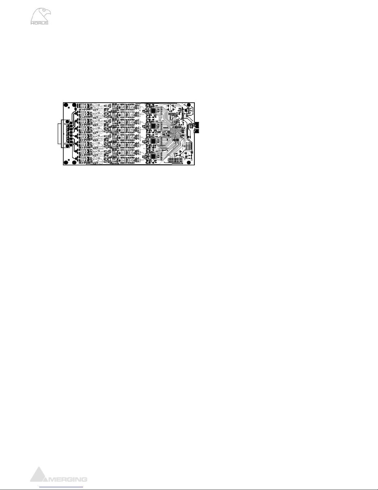
IOM-HORUS AD8/AD8P
These remotely controlled Mic/Line Input cards have set a new benchmark in analog circuitry design. Available
in models that work up to 192kHz (AD8) and DXD/DSD256 (AD8P)
HORUS-AD8/AD8P Key Features
• 8 x exceptionally transparent, Swiss designed pre-amplifiers
on a per channel basis
all parameter changes
itchable per channel
dBu
1.75
122 B
to +60 dB
/±0.2dB
Pre + A/D (20 Hz-20 kHz) @ -2 dBFS (AD8/AD8P) 0.0016 % / 0.001 %
h nnel) S
80 Hz
InputImpedance(Differential) 6.5kΩ
122 dB
Hz) @ -10 dBFS, typ.. -10 0005%)
z, ty
re controlled) +4 d u to +24 dBu
/±0.2dB
Ana.)
HORUS-AD8/AD8P Mic-Pre Analog Section
Frequency response +0/-0.5 dB, Line 5 Hz - 75 kHz
Frequency response +0/-2.0 dB, Line 2.5 Hz - 150 kHz
Frequency response +0/-0.5 dB, Mic 10 Hz - 100 kHz
Frequency response +0/-2.0 dB, Mic 5 Hz - 200 kHz
THD+N (1 kHz), Line/Mic at G=0dB <-115 dB (0.00018 %)
THD+N (20 Hz-20 kHz) , Line/Mic at G=0dB <-112 dB (0.00025 %)
Interchannel Crosstalk @ 1kHz, typ. -135dB
• Remote/Local switch to Line Level
• Completely accessible remotely for
• Phantom Power/Phase/Low Cut sw
• Better than 120dB dynamic range
HORUS-AD8/AD8P Specifications
MIc Pre-Amp + ADC
Mic Pre Max Input (Pad On / Pad Off) +23 dBu / +13
Input Impedance (Differential) kΩ
Dynamic Range (A-weighted, typ.) , dBu dref +13
Gain Range (software controlled) -10 dB
GainStep/Precision 0.5dB
THD+N
Interchannel Crosstalk @ 1kHz, typ. -125 dB
EIN @ >40 dB Gain (150Ω Source Impedance, A-weighted, typ.) -128 dBu
Common Mode Rejection Rate @ 1kHz, typ. 75 dB
Phantom Power (Software Switchable Per Channel) +48V
Phase Reverse (Software Switchable Per C a YE
Low Cut filter (Software Switchable Per Channel) -12 dB/octave,
Line Input
MaxLineInputfor0dBFS +24dBu
Dynamic Range (A-weighted, typ), ref +24 dBu
THD+N Line+A/D (20 Hz-20 k 6 dB (0.
Interchannel Crosstalk @ 1kH p. -125 dB
Sensitivity Range for 0 dBFS (softwa B
GainStep/Precision 0.5dB
Common Mode Rejection Rate @ 1kHz, typ. 75 dB
ConnectorPinout DB-25(Tascam

Horus User Manual
www.merging.com/horus Page 12
5° low-end in-channel Ø deviation pt: Line 13 Hz
iation pt: Mic 35 Hz
Interchannel phase 10 Hz - 100 kHz < ±0.1°
5° low-end in-channel Ø dev
Horus User Manual
www.merging.com/horus Page 13
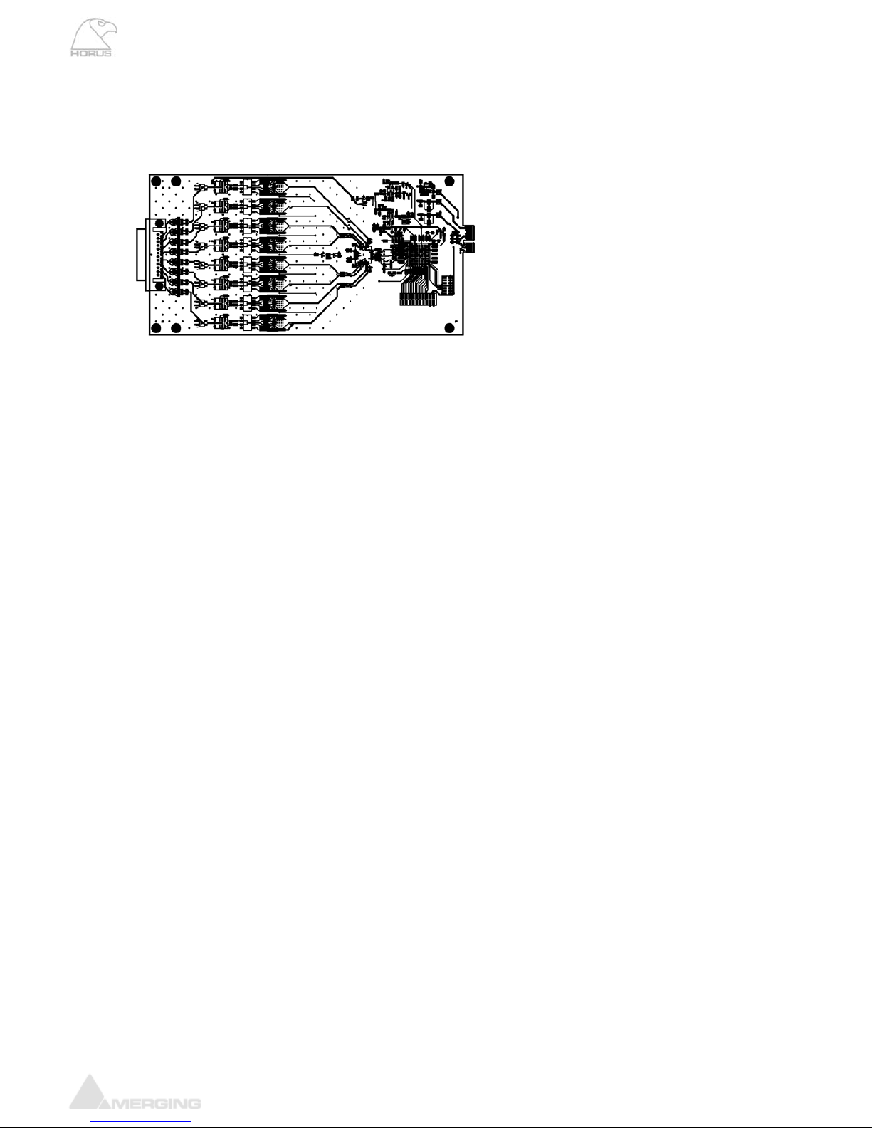
IOM-HORUS DA8/DA8P
The DA8 (up to 192kHz) and the DA8P (up to DSD) have been shown in testing to be consistently the quietest
multichannel D/A conversion modules available anywhere.
IOM-HORUS-DA8/DA8P Key Features
• Auto-mute circuitry for “no-pop” power cycling
edures
ting vels
Specifications
.5 dB
0 Hz 0 kHz
kHz
kHz
Line Output Impedance (Differential) 100 Ω
Dynamic Range (A-weighted, typ) 126 dB
RUS-DA8) < -113dB (0.00022 %)
DB-25(TascamAna.)
Line Output Level calibration
ature both hardware level settings in the form of 4 DIP switches per output
atever local/organization
y once, at product installation, and only if the desired Operating
Line Level differs from the default ex-factory settings of +18 dBu for 0 dBFS.
Procedure for Hardware alignment:
1. Shut down your Horus and make sure that the Horus back panel Power is also switched OFF.
2. Unscrew all DA8 modules that need adjustment.
3. Pull gently out (5-7 cm is enough) to access the DIP Switches. There is one block of 4 dip switches per
channel. Channel 1 is labeled S1, channel 8 is labeled S8.
• Digitally controlled trims for line up proc
• Dynamic range of 127dB (typ.)
• Easy to set dip switches for internation leal opera
IOM-HORUS-DA8/DA8P
Max Line Output @ 0 dBFS (jumpers on +24 dBu) +24 dBu +0/-0
Frequency response +0/-0.3dB @ fs = 48 0 6 Hz – 20
Frequency response +0/-0.3dB @ fs = 2.8224 MHz (DSD) NA / 6 Hz – 20
Frequency response +0/-3.0dB @ fs = 2.8224 MHz (DSD) NA / 2 Hz – 50
THD+N D/A (1 kHz) @ 0 dBFS (IOM-HO
THD+N D/A (1 kHz) @ 0 dBFS (IOM-HORUS-DA8P) < -115dB (0.00018 %)
Interchannel Crosstalk @ 1kHz, typ. -135 dB
ConnectorPinout
The DA8 and DA8P modules fe
channel and a software fine adjustment to align the Analog Output levels to wh
operational levels are mandated.
The Hardware settings are usually to be set onl

Horus User Manual
www.merging.com/horus Page 14
4. Set the DIP Switches as per the table legend printed on the DA8 module card
Output L l (dBu)eve
+24 +18 +15 +12
1ON ON
2 ON ON
3 ON ON
Switch
S1 to S8
4 ON ON
Output Level calibration Example:
Assuming your operating Level is 21 dBu for 0 dBFS (typical of French Radio Broadcasters), you should set the
DIP Switches all OFF (DIP Switch positioned ft, with respect to the picture below) to set maximum
Output Level to +24 dBu (since there is no 21 dBu hardware setting)
to the le

Horus User Manual
www.merging.com/horus Page 15
Once this is set and the DA modules are screwed back in place. Power up the Horus and go to the Horus Setup
t the software attenuation to - 3 dB (see image below), so the overall result ends up at
21 dBu for a Full Scale signal
Page>Module, select each D/A module for software calibration.
In this example case se
Horus User Manual
www.merging.com/horus Page 16
IOM-HORUS-MADM/MADS
The MADI Expansion card (MADM - Multimode / MADS - Singlemode) doubles the total MADI channel count to
128 inputs and 128 outputs @1FS
HORUS-MADM/MADS Features
• MADI Optical and Coaxial inputs and outputs
4 discrete channels of digital input and output (extended mode) at 1FS for a total of 128 inputs
e base unit MADI
• Up to 384 kHz sampling rate as well as DSD 2.8 MHz
• 24-bit resolution
ant MADI (AES 10-1991)
HORUS-RSGP
For installations where extended control is needed, Horus owners can add 8xGPIO and
RS-422 (Sony 9pin) connectivity with this easy to install option
• Additional 6
and outputs combined with th
• Fully compli
Horus User Manual
www.merging.com/horus Page 17
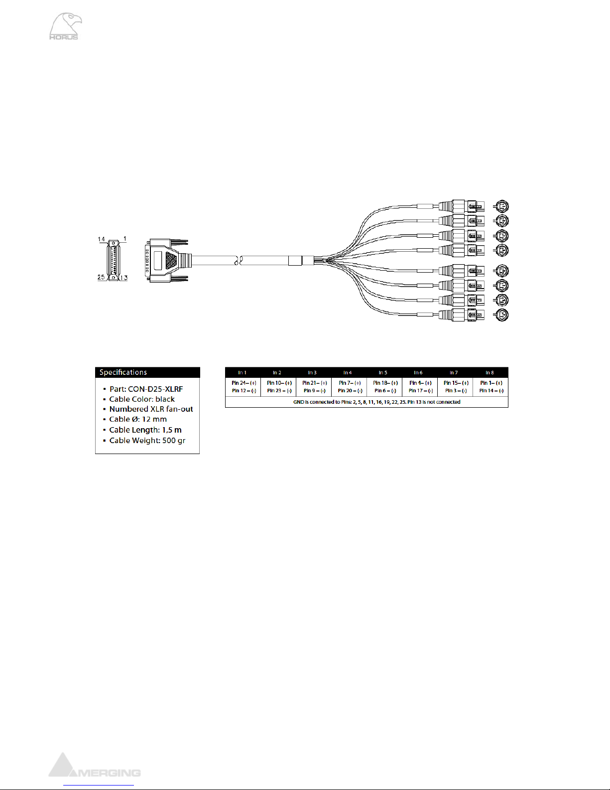
HORUS CABLES
Connecting the analog audio Input cables to the AD8/AD8P module
The AD/AD8(P) modules
s
connect the Mic/Line Inputs using DB25 D-SUB connections.
Please ensure that the cables you have chosen to use, or have had made, conform to this specification before
you attempt to connect them.
he female DSUB port
on the module. Then, with slight pre nnector into place. If your DSUB connector has
retention screws on either side, then fasten them finger-tight once the connector has been pushed into place.
Note: The pinout of the DB-25 is as per Tascam Analog.
* THESE CONNECTIONS ARE NOT MEANT TO SUPPORT ANY SIGNIFICANT WEIGHT.*
Ensure that there is no strain from the connected cable as any significant pressure on the module’s DSUB connector could
damage the Horus unit.
To connect the DSUB connection to the IOC-AD8(P), align the Male cable connector with t
ssure, guide the co

Horus User Manual
www.merging.com/horus Page 18
Connecting the analogue outputs cables to the DA8/DA8P modules
bles you have chosen to use, or have had made, conform to this specification before
you attempt to connect them.
The IOC-DA8(P) modules connect the line outputs using DB25 D-SUB connections.
Please ensure that the ca
To connect the DSUB connection to the IOC-DA8(P), align the Male cable connector with the female DSUB port
nnector has
mounting screws on either side, the er-tight once the connector has been pushed into place.
Note: The pinout of the DB-25 is as per Tascam Analog.
* THESE CONNECTIONS ARE NOT MEANT TO SUPPORT ANY SIGNIFICANT WEIGHT.*
Ensure that there is no strain from the connected cable as any significant pressure on the module’s DSUB connector could
damage the Horus unit.
on the module your DSUB co
n fasten them fing
. Then, with slight pressure, guide the connector into place. If
Horus User Manual
www.merging.com/horus Page 19
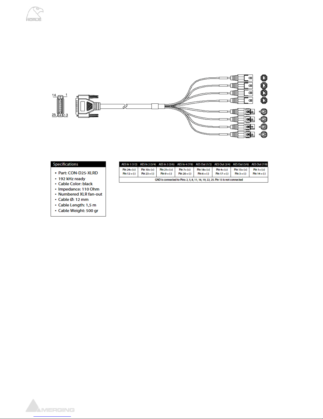
Connecting the AES-EBU cable
hos to use, or have had made, conform to this specification before
you attempt to connect them.
The AES ports connect the AES-EBU I/O using DB25 D-SUB connections.
Please ensure that the cables you have c en
To connect th
r has mounting
screws on either side, then fasten th nce the cable has been pushed into place.
Note: The pinout of the DB-25 is as per Tascam Digital.
* THESE CONNECTIONS ARE NOT MEANT TO SUPPORT ANY SIGNIFICANT WEIGHT.*
Ensure that there is no strain from the connected cable as any significant pressure to the module’s DSUB connector could
damage the Horus unit.
e DSUB connection to the AES port, align the Male connector with the female DSUB port on the
module. Then, with slight pressure, guide the connector into place. If your DSUB connecto
em finger-tightn o
Horus User Manual
www.merging.com/horus Page 20
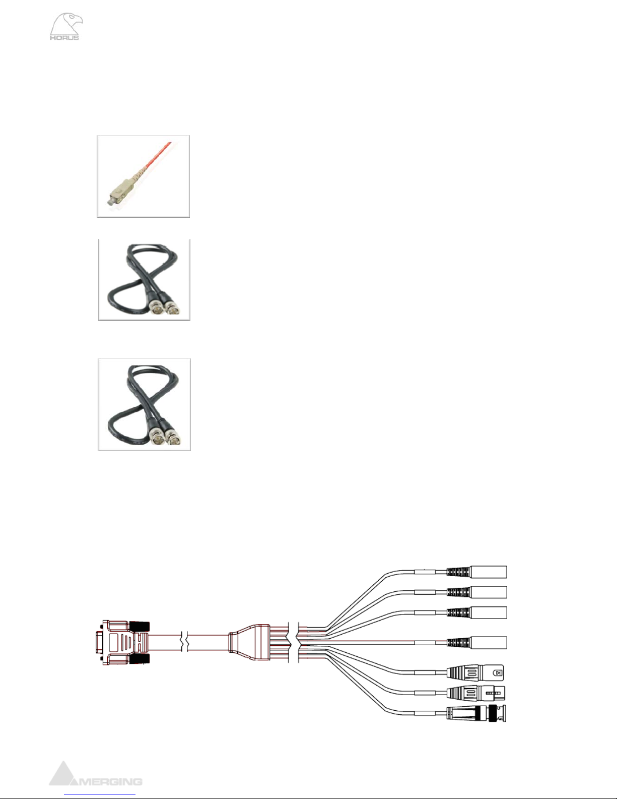
Connecting the MADI cable
The MADI port (both the standard one and the optional MADI Expansion module) can be connected using
either Optical or coaxial cabling.
k area, as dust
y obstruction is present. Remove the cap
on both the cable and the port and slowly / firmly push the cable into the receiving
port on the Horus unit until it clicks into place.
When Using a Coaxial connector. Slowly bring the Male cable up to the female
port, ensuring that the pin in the centre of the male cable lines up with the
le in the female port. Push the connector firmly into place and twist
clockwise until it clicks into its locked position.
The Wordclock connections on the rear of the Horus unit are coaxial BNC’s. To
connect a ordclock source from an external device slowly bring the Male cable up
to the female port, ensuring that the pin in the centre of the male cable lines up
with the receptacle in the female port. Push the connector firmly into place and
Connecting the Sync Cable
The Sync Cable (optional with each Horus unit) is a DB15 cable that connects to the “SYNC” port on the rear of
the Horus unit. The SYNC cable provides connectivity for MIDI, LTC and Video Reference Input and Output for
the Horus unit. To attach this cable to the Horus unit, align the male connector with the female DSUB port on
the module. Then, with slight pressure, guide the connector into place. Once the cable has been pushed into
place, fasten the mounting screws on either side finger-tight.
When using Optical cabling, first ensure that you have a clean wor
and debris can affect the connection if an
receptac
the sleeve
rdclock input/output
Connecting the Wo
twist the sleeve clockwise until it clicks into its locked position.
Other manuals for Horus
2
Table of contents
Other Merging Media Converter manuals


Popular Media Converter manuals by other brands

Sima
Sima GoDVD! CT-2 user manual

Magnimage
Magnimage LED-540 user manual

Advantech B+B SmartWorx
Advantech B+B SmartWorx McBasic TX user manual

Data Translation
Data Translation MACH Series user manual

Comtech EF Data
Comtech EF Data LBC-4000 Installation and operation manual

pumpa
pumpa E-LINE DRIVE-01 Translation of the original instruction manual


