dCS 905 User Manual Manual for Software Issue 1.0x
dCS Ltd November 2006
English version web-site: www.dcsltd.co.uk
Step 1 - Setting the Output Format
do this: On the front panel, press the Menu button and select ADC Settings, 1.1 Output
Mode. Use the Up & Down buttons to move the highlight to the required format,
then press OK.To exit the menu, hold down the Cancel button or wait for
timeout.
do this: Alternatively, use the Format button.
The most common format is PCM. The interfaces available are:
•single-wire AES (one of the 4 AES inputs)
•dual-wire AES (on AES1 / 2 and AES 3 / 4)
•quad-wire AES (on AES 1 - 4)
•SDIF-2 (on DSD/SDIF CH1, CH2 and CLK OUT).
Do not set to DSD or DSD (P3D) unless your recorder or workstation is
equipped with DSD features.
IMPORTANT! DSD signals might damage your speakers when applied to standard PCM
equipment! To PCM units, DSD is just very loud, wide band noise.
The DSD interfaces available are:
•Quad-wire DSD (2 channels of DSD data packed into four 16 bit /44.1kS/s
AES/EBU interfaces – AES 1 - 4)
•P3D (2 channels of DSD data packed into three 24 bit / 44.1ks/s AES/EBU
interfaces - AES 1 – 3)
•DSD SDIF-2 or SDIF-3 (on DSD/SDIF CH1, CH2 and CLK OUT).
Select the 1.2 Filter settings menu and choose the filter you prefer.
Select the 1.5 Word Length menu and set the required PCM word length. If you
choose less than 24 bits, set the 1.4 Noise Shaping menu to a suitable setting.
If in doubt, 9th order gives good results down to 16 bits.
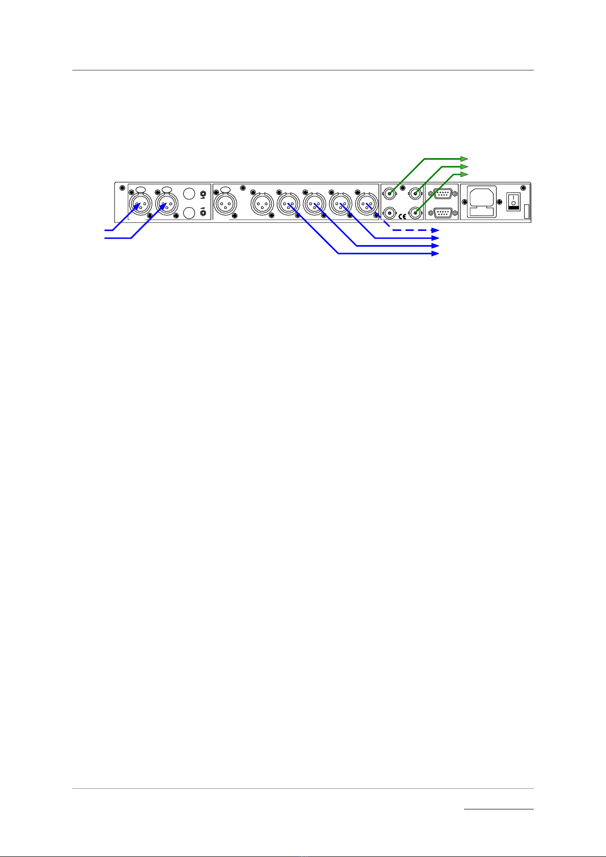
Step 2 – Setting the Connectors
do this: On the front panel, press the Menu button and select Connectors.
do this: If you want to use the 905’s internal clock, use the Ext Sync button to set
Internal or select 2.1 Sync Source > Internal.
do this: If you use an external Word Clock source, use the Ext Sync button to set
Slave: W-Clk or select 2.1 Sync Source > Slave: W-Clk.
do this: If you use an external AES Reference source, use the Ext Sync button to set
Slave: AES or select 2.1 Sync Source > Slave: AES.
do this: If you have selected DSD output format, select 2.3 DSD format and choose the
required mapping.
Step 3 – Connecting the Analogue Inputs
do this: Connect two screened XLR cables from your analogue source to the balanced
inputs.
do this: If necessary, you can adjust the balanced input full scale levels using the two
Sensitivity trimmers mounted on the rear panel. Use a small flat-bladed
screwdriver or trim tool. Take care to keep the two channels balanced in level.
Make sure the input level does not exceed the full-scale indication on the front
panel meters.