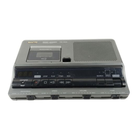
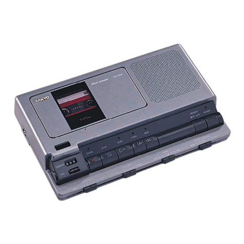
Sanyo M1011 User manual

SERVICE
MANUAL
MINI
CASSETTE
RECORDER
SPECIFICATIONS
Power
Source
DG
ee
ea
6V
(UM-3,HP
7,
AA
Cell,
Mignonzelle,
R6)
x
4
Outpt
POWer
eee
es
500mW
(Max.)
Current
Consumption
(at
Vol.
Min.)
Record
mode)
ree
Ae
eee.
140mA
Playback
MOG:
s+
cnencmawer
cena
eee:
120mA
Fast
Forward
mode
...:.......:s.-..:csi
220mA
Rewind
moder
i.
fe
220mA
Recording
System
<2...
ie
DC
Bias
Erasing:
SYSICM)
=
i
te
cb
ec
Magnet
Erasing
Tape
Speed
Se
ees
1-7/8ips.
£3%
Pitch
GOnIOR
ee
eee
+20%
~
—10%
Fast
Forward
Time
ee
ee
ee]
150sec.
(with
C-60)
Rewind
Time
.........
Wow
&
Flutter
........
ee
Frequency
Response
(Overall)
..........
Erase
Ratio
(Overall)
Signal
to
Noise
Ratio
Crosstalk
Track
to
Track
Harmonic
Distortion
(K3)
ae
eee
ee
ee
ee
ee
ese
ee
we
ee
ee
ee ee
eee
eee
ee
ee
ee
Hum
&
Noise
(at
Vol.
Min.)
at
Vok-
Ming
222:
at:
Volk:
Max.
te:
Terminal
Impedance
MIC...
a
Ext.
Speaker
a
Ce
ee
Ce
ee
ee
Ce
ee
—Specifications
subject
to
change
without
notice.—
142
436
08]
150sec.
(with
C-60)
0.4%,
WRMS
200Hz
~
6,000Hz
40dB
30dB
50dB
10%
—50dBs
—30dBs
3k
80
WM-13274

DISASSEMBLY
INSTRUCTIONS
vABINET
BOTTOM
REMOVAL
2.
|.
Remove
the
four
screws
(1
~
4)
fastening
the
Cabinet
Bottom
and
detach
the
Cabinet
Bottom
by
lifting
it,
noting
the
3.
speaker
and
shield
plate
leads.
Jack
Cabinet
(2)
Cabinet
Bottom
Cabinet
Front
2,
The
Jack
Cabinet
and
Cabinet
Front
can
be
removed
from
the
unit
by
detaching
the
Cabinet
Bottom.
Jack
Cabinet
Cabinet
Front
G
on.
3.
Reassemble
in
reverse
order.
AMPLIFIER
P.C.BOARD
REMOVAL
1.
Remove
the
Cabinet
Bottom
by
following
the
instructions
and
then
unsolder
the
speaker
leads
(blue
and
red)
and
the
leads
for
the
power
supply
(brown
and
black)
from
the
P.C.Board.
Remove
the
two
screws
(5
and
6)
fastening
the
P.C.Board.
Remove
the
Amplifier
P.C.Board
by
lifting
it
in
the
direction
of
the
arrow,
noting
the
lead
wires
of
the
Indicator
P.C.Board
and
Buil-in
Microphone.
If
necessary,
unsolder
their lead.
Reassemble
in
reverse
order.
MECHANISM
CHASSIS
REMOVAL
1.
Remove
the
Cabinet
Bottom
by
following
the
instructions
and
unsolder
the
shield
plate
lead
(gray),
the
speaker
leads
(blue
and
red),
and
the
leads
for
the
power
supply
(brown
and
black)
from
the
Amplifier
P.C.Board.
2.
Open
the
Cassette
Compartment
Lid
by
pressing
the
STOP/EJECT
button
and
remove
the
fastening
screw
(7).
3.
Remove
the
post
(8)
and
the
two
screws
(9
and
10)
fastening
the
Chassis.
Detach
the.
Mechanism
Chassis
from
the
Cabinet
Top
by
lifting
it,
noting
the
lead
wires
of
the
Indicator
P.C.Board
and
Built-in
Microphone.
If
necessary,
unsolder
their lead.
Reassemble
in
reverse
order.

ADJUSTMENTS
GENERAL
REMARKS
®
Before
adjustment,
wipe
the
tape
contacting
surfaces
clean
as
well
as
the
contacting
surfaces
of
the
driving
parts
with
a
soft
cloth
soaked
in
alcohol.
|
Trouble
may
occur
because
of
oil
and
grease
stains.
®
Carefully
handle
the
belt
because
grease
easily
attaches
to
it.
Then,
check
the
used
rubber
parts.
lf
the
rubber
has
deteriorated
or
is
scratched,
replace
the
parts
with
new
ones.
EQUIPMENT
REQUIRED
e
VTVM
e
Frequency
Counter
@
Dummy
Load
(82)
e
Test
Tapes
*
3kHz
Test
Tape
(Example:
TEAC
MTT-111)
for
Tape
Speed
Adjustment
*
8kHz
Test
Tape
(Example:
TEAC
MTT-113C)
for
Head
Azimuth
Adjustment
e
DC
Constant-voltage
Regulator
e
Alignment
Tool
NOTE:
Supply
6V
DC
to
the
Ext.
Power
Jack
from
the
constant-voltage
regulator
at
the
adjustment.
TAPE
SPEED
ADJUSTMENT
1.
Remove
the
battery
compartment
lid
and
connect
a
frequency
counter
to
the
earphone
jack
as
illustrated.
Then,
insert
a
3kHz
test
tape
(Example:
TEAC
MTT-111)
into
the
cassette
compartment.
Frequency
Counter
3KHz
ea
3%]
Potentiometer
(P101)
for
Tape
Speed
Adjustment
2.
While
playing
back
the
test
tape,
adjust
the
tape
speed
by
turning
the
potentiometer
(P101)
on
the
P.C.Board
until
the
frequency
counter
reads
3kHz
(+3%).
HEAD
AZIMUTH
ADJUSTMENT
1.
Connect
a
VTVM
to
the
earphone
jack
as
illustrated
and
insert
a
8kHz
test
tape
(Example:
TEAC
MTT-113C)
into
the
cassette
compartment.
VTVM
(Max.)
Dummy
Load
80,
Adjustment
R/P
Head
Adjusting
Screw
2.
While
playing
back
the
test
tape,
slowly
turn
the
azimuth
adjusting
screw
until
the
VT
VM
reads
the
maximum.
3.
After
the
adjustment,
secure
the
adjusting
screw
with
paint
or
glue.
sc
ae
Se
ested
ac
ten
arnt
le

PARTS
LIST
oe
Part
No.
Description
Q’ty
PACKAGE
141
6
1419
64707
—
Individual
Carton
1
141
6
1449
81800
Styrofoam
Case
1
141
6
2519
12090
Poly
Cover
(Unint)
1
141
6
3919
41700
Plain
Pad
1
141
6
4559
00100
Serial
No.
Sheet
3
ACCESSORIES
142
6
4119
32362
Instruction
Manual
1
CABINET
CAI
141
0
1119
87209
Completed
Cabinet
Top
1
CA2
141
2
4469
17200
Cushion
2
CA3
141
2
2149
15300
Bracket
Cabinet
1
CA4
141
2
1119
83201
Cabinet
Jack
4
CA5
141
2
2529
05400
=
Shaft
1
CAG
141
2
1769
07100
Hand
Strap
1
CA7
=:
144.
2:
1119
82203
Cabinet
Front
1
CA8
141
2
1519
36300
Decorative
Cabinet
1
CA9
=
=141
2
2449
45300
Sheet,
Mike
1
CA10
4
1539
70620
Microphone
[BM1]
1
CA11
141
2
3899
10100
Holder
Mike
1
CA12
4
2269
37520
_LED
Indicator
P.C.B.
Assy
[See
PCB2]
1
CA13.
141
2
4219
21800
Screw,
Pan
Hd.
Tapping-2,
+M1.7x3.0
3
CAi4
141
2
7539
21800
Post,
Cabinet
1
CA15
4
1329
78092
Amplifier
P.C.B.
Assy
[See
PCB1]
1
CAi6
141
2
1639
50000
Control
Knob
1
CA17
=141
2
4219
23500
Screw,
+M1.7x4.0
1
CA18
141
2
4469
14502
Cushion
2
CAI9
141
2
4469
17201
Cushion
4
CA20
141
0
1119
87127
Cabinet
Bottom
Assy
1
CA21
4
1519
71420
Speaker
(8)
[SP1]
1
CA22
141
2
3729
03201
Bracket,
Speaker
2
CA23
=
141
2
3229
39000
Shield
Leaf
1
CA24
141
2
2899
26600
Adhesive
Sheet
1
CA25
141
2
4469
35200
Cushion
1
CA26
141
2
1339
28307
Battery
Lid
1
Cx1
101
3
1302
00811
Screw,
Pan
Hd.,
+M2.0x8
1
CX2
101
3
1302
01211
Screw,
Pan
Hd.,
+M2.0x12
1
CX3
103
3
1302
00511
Screw,
Pan
Hd.
Tapping-2,
+M2.0x5
1
CX4
103
3
1302
00614
Screw,
Pan
Hd.
Tapping-2,
+M2.0x6
1
CX5
128
3
1317
04014
PI
Screw-3,
Pan
Hd.,
+M1.7x4.0
1
CX6
128
3
1320
04014
Pl
Screw-3,
Pan
Hd.,
+M2.0x4.0
1
CX7
128
3
1320
06014
PI
Screw-3,
Pan
Hd.,
+M2.0x6.0
2
CX8
131
3
1302
00411
Screw,
Pan
Hd.
C
SW,
+M2.0x4
1
CXx9
143
3
1702
00618
Screw,
Bind
Hd.
Tapping-B,
+M2.0x6
1
NOTE:
1.
Parts
order
must
contain
Model
Number,
Part
Number
and
Description.
2.
Ordering
quantity
of
screws
and
resistors
must
be
multiple
of
10
pes.
ae
nd
hg
ds
ie

CABINET
EXPLODED
VIEW
—5—

Ref.
No.
MCI
MC2
MC3
MC4
MCS
MC6
MC?
MC8&
MC9
MC10
MC11
MC12
MCi3
MC14
MC15
MC16
MC17
MC18
MC19
MC20
MC21
MC22
MC23
MC24
MC25
MC26
MC27
MC29
MC29
MC30
MC31
MC32
MC33
MC34
MC35
MC36
MC37
MC38
MC39
MC40
MC41
MC42
MC43
MC44
MC45
MC46
MC47
MC48
MC49
MC50
MC51
MC52
MC53
MC54
MC55
MC56
MC57
MC58
MC59
MC60
MC61
MC62
MC63
Part
No.
MECHANISM
141
141
141
143
14]
141
141
141
141
14]
141
141
141
141
141
14)
141
141
141
141
141
141
141
141
141
141
141
144
141
141
141
141
141
141
141
141
141
141
141
141
141
141
141
141
144
141
141
141
141
141
141
141
141
141
144
141
141
141
141
141
0
3119
21300
2
3769
13500
2
8139
08902
2
7539
21800
2
4219
28100
0
7419
37200
2
8519
94300
2
8519
44100
2
8419
11901
2
7419
81800
2
8419
11800
2
8529
10800
2
7419
82500
2
8519
61100
2
7149
05800
2
4459
25200
0
7319
25601
2
8219
32000
2
3529
36000
2
8529
10700
2
7439
30600
2
4539
21800
4
2429
71241
2
4219
28300
2
4219
31900
2
8519
47400
4
2429
71250
2
4729
01900
2
3529
18101
2
8529
11100
Q
5459
01900
2
8529
11200
2
8539
46800
0
7419
35901
2
4219
13201
2
8549
16400
2
7419
84200
2
8529
10600
2
4539
29600
4
5279
71180
2
2449
45200
2
4459
26800
2
4219
23300
2
8529
11000
2
5519
46400
2
4539
15800
0
7419
35801
0
7419
35601
2
3169
19700
2
8549
07600
2
8549
16500
2
8549
19800
2
4539
29800
2
5519
46000
2
8559
03300
0
5219
09000
2
5649
20300
0
3129
01500
2
7419
81600
2
8529
13000
0
5319
07000
2
4539
28900
2
8559
04300
MECHANISM
PARTS
LIST
Description
Chassis
Assy
Spacer
Counter
Bracket
Post,
Cabinet
Screw,
Pan
Hd.,
+M2.0x8.6
Record
Rod
Assy
Spring,
Lock
Plate
Spring,
Interlock
Record
Lock
Lever
Eject
Lever
Interlock
Lever
Spring,
Interloc
Play
Rod
Spring,
Slide
Brake
Arm
Brake
Cover
Slide
Base
Assy
Guide
Tape
Spacer,
Head
Spring,
Erase
Head
Arm
Erase
Head
Arm
Washer,
M2.6x4.7x0.25
Erase
Head
[HD2]
Screw,
Pan
Hd.
Tapping
w/Washer,
+M2.0x10.0
Screw,
Pan
Hd.
w/Washer,
+M2.0x12.3
Spring,
Head
R/P
Head
[HD1]
Lug
Spacer,
Head
Spring,
Slide
Base
Pinch
Roiler
Arm
Assy
Spring,
Pinch
Roller
Spring,
Cassette
Completed
Pause
Rod
Screw,
Pan
Hd.
w/Washer,
+M2.0x6.0
Spring,
Pause
Rod
Pause
Lock
Lever
Spring,
Pause
Latch
Washer,
M1.2x3.0x0.3
Motor
[M1]
Sheet
Cushion,
Motor
Screw,
Pan
Hd.
w/Washer,
+M2.0x6.5
Spring,
Play
Rod
Take-up
Idler
Washer,
M2.1x4.5x0.4
Completed
Rewind
Rod
Completed
F.FWD.
Rod
Bracket
Plate
Spring,
lock
Recrod
Spring,
Stop/Eject
Rod
Spring,
F.PWD
Rewind
Rod
Washer,
M2.6x4.7x0.13
Capstan
Gear
Spring,
Flywheel
Flywheel
Assy
Capstan
Belt
Reel
Plate
Assy
Shut-off
Lever
Spring,
ASO
Cancel
Take-up
Ree}
Assy
Spindle
Washer,
M1.7x3.4x0.4
Spring,
Supply
Q
~-
<
=
pow
eee
enon
ws
ep
enmraten
st
wrest
oY
SB
Heese
en
est
Bw
eBe
Br
Bet
Be
AH
NH
ABVreaer
et
2
Ht
FP
42N
Steerer
rer eer
ete
rt
I
Ref.
No.
MC64
MC65
MC66
MC67
MC68
MCc69
MC70
MC71
MC72
MC73
MC74
MC75
MC76
MC77
MC78
MCc79
MC80
MC81
MC82
MC83
MC84
MC85
MC86
MC87
MC88
M21
MZ2
MZ3
M24
MZ5
MZ6
MZ7
MZ8
141
141
141
141
141
141
141
144
141
141
141
141
141
141
141
141
144
141
141
141
141
141
144
14]
141
101
101
Part
No.
0
5319
07100
0
7439
11200
2
5519
46100
2
7439
30400
2
7439
30500
2
8549
18400
2
7419
81700
2
8549
15200
2
4539
09300
2
5519
46200
2
4539
30300
2
4539
01402
2
4469
17201
0
7419
35701
2
8549
16600
2
7319
54100
2
7319
54000
2
7419
81900
2
8429
06300
2
8519
84300
2
8519
33000
2
4539
20200
2
7319
53700
2
8549
15300
2
4469
40200
3
1302
00511
3
2502
00711
110
3
1102
00023
112
3
1302
00082
112
3
1302
50082
127
3
1317
02013
143
3
1702
00618
143
3
1202
01018
NOTES:
1.
Parts
order
must
contain
Model
Number,
Part
Number
and
Description.
2.
Ordering
quantity
of
screws
and
resistors
must
be
multiple
of
10
pcs.
Description
Reel
Supply
Assy
Rewind
Arm
Assy
Rewind
Gear
Selector
Link
Fast
Arm
Spring,
Fast
Arm
F.FWD.
Lever
Spring,
F.FWD.
Rewind
Arm
Washer,
M2.6x5.5x0.2
Fast
Gear
Washer,
M2.1x4.5x0.3
Washer,
M2.1x6.0x0.5
Cushion
Stop
Rod
Assy
Spring,
Eject
Plate
Eject
Piate
Lock
Plate
Cue
Review
Lever
Record
Plate
Spring,
Flywhee!
Support
Spring,
Index Lever
Lock
Washer,
M2.4x4.0x0.3
Take-up
Arm
Spring,
Take-up
Arm
Cushion
Screw,
Pan
Hd.,
+M2.0x5
Screw,
Cylinder
Hd.,
-M2.0x7
sm.
Round
Washer,
M2.0
E
Ring,
M2.0
E
Ring,
M2.5
P!
Screw-1,
Pan
Hd.,
+M1.7x2.0
Screw,
Bind
Hd.
Tapping-B,
+M2.0x6
screw,
Flat
Hd.
Tapping-B,
+M2.0x10
Q’ty

MECHANISM
EXPLODED
VIEW
(Chassis
Top)
Mc24—©
Nzz——e
©—MLI
Mz3——b
>
—Me2s
N23)
|
wcze—o:
a
:
mc26
——&
<—
Mezs
mc21
|
McZ0—
35
rsa
MC19
ii
mcg
eae
Z
)
MI3—ae
ee
Ls
7
KE
aie
eT
OES
ee
ee
ee
Ee
ee
er

MECHANISM
EXPLODED
VIEW
(continue)
(Chassis
Bottom)
MC56
MC55
———-3
=
M53
a
37
MCc52
wzI—e
av
MCS

P.C.BOARD
PARTS
LIST
ial
Part
No.
Description
Q’ty
AMPLIFIER
P.C.B.
ASSY
PCB1
4
1329
78092
Amplifier
P.C.B.
Assy
1
4
2269
37500
PRC
Board
1
141
2
4729
04700
Staple,
10mm
8
Jt
4
2359
75472
1P
Jack
(Mike)
1
J2
4
2359
75472
1P
Jack
(Earphone)
1
J3
4
2359
75461
=
1P
Jack
(Remote)
1
J4
4
2359
76360
Ext.
Power
Socket
1
S1
4
2319
73400
Slide
Switch
(Record/Play)
1
S2
4
2319
74490
_
Leaf
Switch
(Power)
1
P101
4
2229
73790
_-
Potentiometer
(B-3k)
1
VR1
4
2229
73572
Volume
Control
(A-30k)
1
TH101
204
5
9000
00200
Thermister,
SDT
20
1
D1
202
5
9110
18820
Diode,
15
188
1
Q1
203
5
5100
69372
_‘
Transistor,
2SC
693
1
\C1
206
5
1084
14010
1IC,LA
4140
1
(C101
206
5
1555
51220
=
IC,
LAS512
1
C1
CM33
3500
KOOTV
Mylar
0.033uF
50V
+10%
1
C2
CT4
7
363A
MOOAV
Tantalume
0.047uF
63V
+20%
1
C3
CTi
0
563A
MOOAV
Tantalume
1uF
6.3V
420%
1
C4
CD4
7
5350
0002V
Electrolytic
47uF
35V
1
C5
CCi
2
2500
KEOOC
Ceramic
0.0012uF
50V
+10%
1
C6
CD4
7
663A
0001V
Electrolytic
47uF
6.38V
1
C7
CT1
0
463A
MOOAV
Tantalume
O1uF
63V
+20%
1
C8
CD4
7
5250
0001V
Electrolytic
47F
25V
1
C9
CD4
7
5160
0004V
_
Electrolytic
47uF
16V
1
C10
CC1
0
2500
KEOOC
Ceramic
0.00iuF
50V
+10%
1
C11
CD1
0
763A
0001V
Electrolytic
100uF
6.3V
1
C12
CD2
2
740A
0002V
Electrolytic
220KF
4V
1
C13
CC1
2
2500
KEOOC
Ceramic
0.0012uF
50V
+10%
1
C14
CC5
6
1500
KEOOC
Ceramic
560pF
50V
+10%
|
C15
CD4
7
6100
0003V
_
Electrolytic
474F
=.
10V
1
C16
CM68
3500
KOOTV
Mylar
0.068uF
50V
+10%
1
C17
Cli
0
3250
KEOOC
Boundary
0.01uF
25V
+10%
1
C18
CD2
2
740A
0002V
_
Electrolytic
220KF
4V
1
C19
CD4
7
640A
0002V__
Electrolytic
47pF
4V
1
C20
4
2239
70520
Capacitor
220KF
«6.3
1
C21
CD2
2
7100
0003V
_
Electrolytic
220uHF
86
10V
1
C101
CD47
4500
0002V
Electrolytic
0.47u4F
50V
1
C102.
CC2
2
3250
KEOOC
Ceramic
0.022uF
25V
+10%
1
R5
RD1
0
5251
KM000
Carbon
iMQ
=
1/4W
+10%
1
R6
RD1
5
3251
JM000
Carbon
15kQ
1/4W
+5%
1
R12
RP5
6
3121
JVO00
Pretty
Carbon
56kQD
«=1/8BW
+5%
1
R16
RP1
0
0121
JHOOO
Pretty
Carbon
100
1/8W
=+5%
1
R18
RP1
0
0121
JVO00
Pretty
Carbon
100
1/8W
=+5%
1
R22
RD4
7
0251
KM000
Carbon
470
1/4W
+10%
1
R101
RP1
81121
JHOOO
Pretty
Carbon
1800
i1/8BW
=+5%
1
R103.
RP5
6
2121
JV000
‘Pretty
Carbon
56kQ
1/BW
+5%
1
R102.
RD8
2
1251
JMO00
Carbon
8200
1/4W =+5%
1
LED
INDICATOR
P.C.B.
ASSY
PCB2
4
2269
37520
LED
Indicator
P.C.B.
Assy
1
4
2269
37510
PRCLED
1
D1
4
2029
72090
LED
(Record/Battery)
1
NOTES:
|
1.
Parts
order
must
contain
Model
Number,
Part
Number
and
Description.
:
2.
Ordering
quantity
of
screws
and
resistors
must
be
multiple
of
10
pcs.
IC
&
TRANSISTOR
LEAD
IDENTIFICATION
2SC536
2SC693
:
ECB
ECB
LA5512
FRONT
VIEW/BOTTOM
VIEW
1234
TERMINAL
NAME
‘B—
BASE
C—
COLLECTOR
E—
EMITTER
LA4140
FRONT
VIEW/BOTTOM
VIEW
LA5512
BLOCK
DIAGRAM
Reference
Voltage
Circuit
LA4140
BLOCK
DIAGRAM
Ripple
Filter
Driver
Amp.
Phase
Negative
Phase
P.C.
IN
N.F.
P.C.
GND
OUT
B+
Bootstrap
Ripple
Filter
D.C.
Compensation
Feedback
Compensation
spa
GRASS
vASn
Rao
ROTA
TSE
EE
ere
de
BR
oon
ona
Rae
cee
irik
A
ee
AMEE
RMT
BEBE,
ane
SEn
an
re
AR
Bese
EA
ROR
Hans
EES
SE
eee
eg
sale
cae
gta
sg
ee
ghee
peg
en
wo
3
orca
he
CRA
Na
Bigs
MRE
AES
gi
a
BOE
EGU
BE
ND
I
OEE
TE
AE
OEIC
EYEE
ACARI
Att

WW
E
a
=
BATTERY
**AA’*CELL
X4
6V
GRAY
WHITE
+
J4
EXT.
POWER
JACK
BLUE
+
GRAY
2
J2
EARPHONE
JACK
Ji
MIKE
JACK
J3
REMOTE
JACK
es]
ee
SP
|
SPEAKER
M
|
MOTOR
VR
I
CONTROL
VOLUME
BLUE
BM
|
BUILT-IN
MIKE
(REC
/BATT,
—11-
|
2s
;
.

SCHEMATIC
DIAGRAM
oi
2SC693
ict
LA4140O
PRE-AMPLIFIER
POWER
AMPLIFIER
4.9V
.
|
6V
+]
C2
BM|
=
BUILT-IN
MIKE
+
C10
VRI
A.
30K
ie
lu
VOLUME
_,
-
Jt
3
MIKE
JACK
_
D
|
2
R23
)
NL424
390
PY
(REC./
BATT.)
0.06l2p
10
3
|
icioi
LA551l2
HD
2
|
ERASE
HEAD(
MAGNET)
=
:
MOTOR
GOVERNOR
CIRCUIT
a3
J3
REMOTE
JACK
Ww
On
nN
On
Of
al
POWER
SWITCH
J4
EXT.
POWER
JACK
-
Signal
flow
of
PLAY
"AA
CELL
X
4
6V
»
Signal
flow
of
RECORD
SOV
|
Lcio2
|
=
tt
oO
(2)
N
N
sa
iE
-
4
Record/Play
Switch
S2
|
Power
Switch
S3
|
Mike
Sense
Switch
—13-
4
4—
Table of contents
Other Sanyo Microcassette Recorder manuals

Sanyo
Sanyo MCD-S730F User manual

Sanyo
Sanyo 530M - TRC Microcassette Dictaphone User manual

Sanyo
Sanyo TRC-3640 User manual

Sanyo
Sanyo TRC-6300 User manual

Sanyo
Sanyo TRC-8800 - Cassette Transcriber User manual

Sanyo
Sanyo MCD-X75L User manual

Sanyo
Sanyo M1110 User manual

Sanyo
Sanyo TRC 8080 - Cassette Transcriber User manual
Sanyo
Sanyo TRC540M - Auto Stop Microcassette Recorder User manual

Sanyo
Sanyo TRC-5880 User manual