SERVICE
MANUAL
MINI
CASSETTE
RECORDER
142
431
25
(Black)
142
431
35
(Silver)
SPECIFICATIONS
Power
Source
Fast
Forward/Rewind
Time
..............
1
20sec.
(with
C-60)
DIES
ahs
caeeeailevnne
ede
euie-dauadne
seenawe
sees:
3V
Wow
&
Flutter
.............
0c.
c
eee
eee
eee
0.5%,
RMS
(UM-3,HP
7,
AA
Cell,
Mignonzelle,
R6)
x
2
Frequency
Response
(Overall)
Output
Power
.................cceeeeeeeeees
350mW
(Max.)
10dB
Band
.................ccc
cece
eeeeeee
200Hz
~
6,000Hz
Current
Consumption
(at
Vol.
Min.)
Erase
Ratio
(Overall)
......................
40dB
Record
mode
............cccccecseeeeeeeee
160mA
Signal
to
Noise
Ratio
......................
30dB
Playback
mode
.............c.ccccceeeees
160mA
Crosstalk
FastForward/Rewind
mode............
250mA
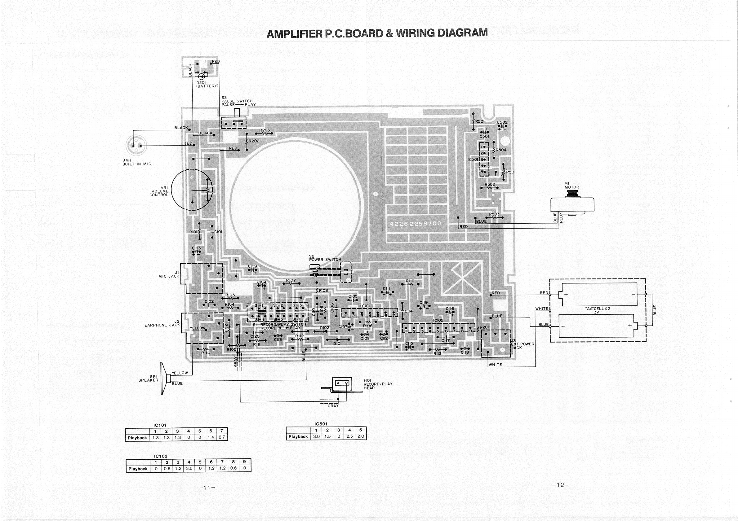
TRACK
10
TRACK
osc
csacs
dncneoes
cosceneenes
60dB
TrackSystem
..............ccceeeeeees
ssn
2
Track/Mono
Harmonic
Distortion
(K3)
.................
13%
Recording
System
................ecceeeees
DC
Bias
Hum
&
Noise
(at
Vol.
Min.)
................
—60dBs
Erasing
System
.........
0...
cc
cece
cence
eee
Magnet
Erasing
Terminal
Impedance
TAP
Speed
ccc
ccciaccesces
cawesivssseverces
1-7/8ips.
£3%
PNG:
waryutern
nee
cdeus
hit
edietedaatmessaaus
0.3mV/6.8k0
Torque
EParOnOne:
245
ins
seducegsecuswdeedeween
cee
200mV/40
load
Playback
mode
...............cceeeeeeee.
30
~
50g-cm
Dimensions...................
86.5(W)
x
127.5(H)
x
36.5(D)
mm
Fast
Forward/Rewind
mode............
more
than
60g-cm
Weight
(w/o
battery)
..................000.
270g
—Specifications
subject
to
change
without
notice.—
WM-16375