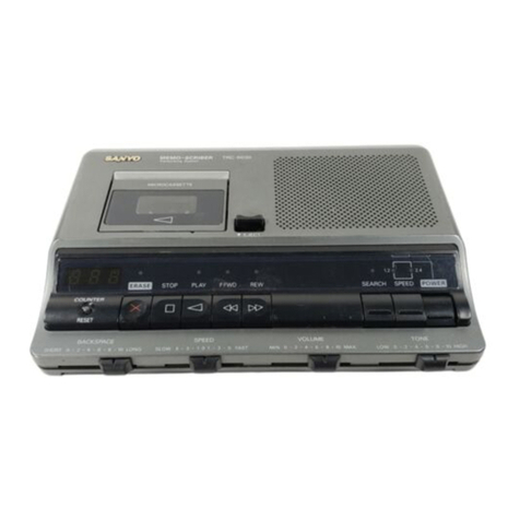
Sanyo TRC-6300 User manual

IFILE NO. I
Service Manual
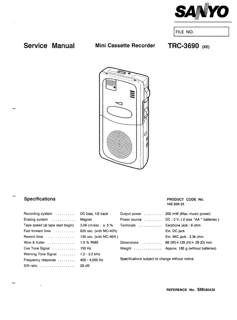
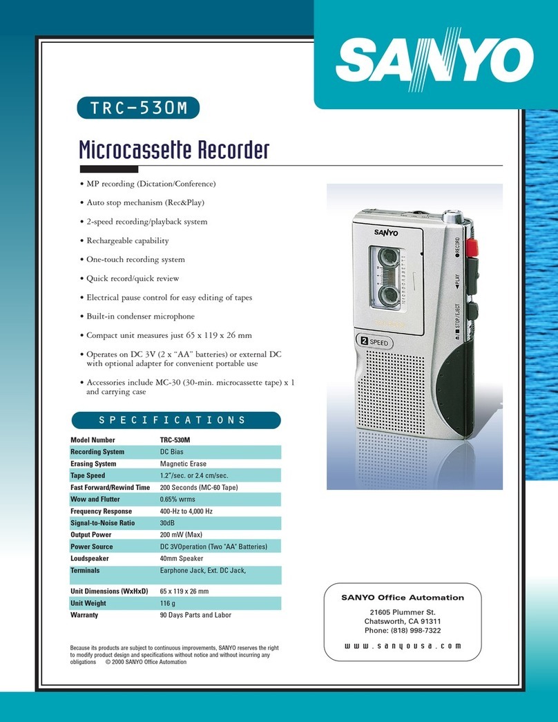
~Specifications
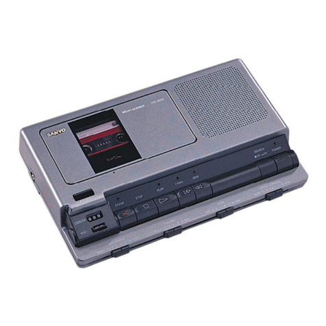
MEMO -SCRIBER TRC-6300 (XE)
Dictating /Transcribing
System (UK)
(NZ)
,>,,,,.
,“,.
,..,,,:,:,:.... .,:
,,,........,.::.:,>
,.,
., .,:,+ .:;,:.
:.:.:.:. ~.:.:.:.:.:.:. fi.:.:.}
[0””””””””
PRODUCT CODE No.
142 968 00 (XE)
142 968 05 (UK)
142 968 06 (NZ)
Recording system .......... AC bias Output power ....... 700 mW (DC MAX.)
Erase system .............. DC erase Loud speaker ....... 66 mm (D) 8ohms
Fast forward /Rewind time .... 420 sec. (MC-60) Dimensions ........ 220 (W) x 160 (D) x46 (H) mm
Wow and flutter ............ 0.35 ‘A RMS Weight ............ 753g
Frequency response ......... 250 Hz -4,000 Hz DC input ........... DC9V
Signal to noise ratio ......... 40 dB
Specifications subject to change without notice.
REFERENCE No. SM580517

REMOVAL AND INSTALLATION
●Disconnectthepower cord’s plug from the electrical outlet.
●All wiring should be returned to the original position after work is completed.
a. CABINET, BOTTOM
w
CABINET &WIRING LAYOUT
(f
-1-

TAPE DECK ADJUSTMENTS
a. HEAD REPLACEMENT AND AZIMUTH ADJUSTMENT
(a) Head Replacement
.After replacement, demagnetize the heads by using a
head eraser.
●Be sure to clean the heads before attempting to make
any adjustment.
(b) Head Azimuth Adjustment
(1) Load the test tape (OA-A411, etc. :6,300 Hz) for
azimuth adjustment.
(2) Press the PLAY button.
(3) Use across-tip screwdriver to turn the screw for
azimuth adjustment so that the outputs are maximized.
(4) After completion of the adjustment, use thread lock
(TB-1 401 B) to secure the azimuth-adjustment screw.
b. MOTOR SPEED ADJUSTMENT
(1) Insert the test tape (OA-W411, etc. :3,000Hz).
(2) Press the PLAY button.
(3) Adjust SVR so that the frequency counter shows are
reading of 3,000 Hz.
HEAD AZIMUTH
ADJUSTMENT
.
c. CHECKING THE MECHANISM TORQUES AND TENSION
.Clean the head, capstan and pinch roller before making any measurement
Measurement Take-up torque Tape tension
Cassette for PLAY: TW-llll ADrive-power cassette
measurement F.FWD/REW :TW-1231A TW-1412
PLAY 7- 16gr.cm 30qr(MlN.)
jF. FWD/REW I40 ar.cm (MIN.) I--- I
-2-

EXPLODED VIEW (CABINET &CHASSIS)
TM-6300MEC –53
%
20
–4
]1
P
D
9, –51
-5
&l j–5
–Y 1
I18
1
w
4
-3-

PARTS LIST
PRODUCT SAFETY NOTICE
Each precaution in this manual should be followed during servicing. Components identified with the IEC symbol Ain the parts
list and the schematic diagram designate components in which safety can be of special significance. When replacing acomponent
identified &use only the replacement parts designated, or parts with the same ratings of resistance, wattage or voltage that are
designated in the parts list in this manual. Leakage-current or resistance measurements must be made to determine that exposed
parts are acceptably insulated from the supply circuit before returning the product to the customer.
CAUTION: Regular type resistors and capacitors are not listed. To know those values, refer to the schematic diagram.
N.S.P :Not available as service parts.
ACKIN
Ref. No.
ABINE
Ref. No.
&ACCESSORIES
Part No.
614 270 8613
614 271 7141
614 271 7158
614 269 9003
614 269 9010
645 010 3131
645 011 2287
614 270 8576
614 269 8990
614 176 1190
614 269 9041
614 271 7264
614 271 7271
645 009 6419
614 250 6028
645 002 8175
645 002 8953
/?1645 010 5166
L?J645 010 5180
~645 010 5197
&CHASSIS
Part No.
614 268 5082
614 268 4986
614 268 5044
614 268 4993
614 122 0796
614 267 9487
614 267 9531
614 268 5198
614 267 9524
614 267 9647
614 268 5204
614 269 5906
614 269 5913
614 269 5920
614 269 5937
614 269 5944
614 269 5951
614 269 5968
614 267 9326
614 267 9470
614 267 9401
614 253 0368
‘IXING PARTS
Description
CARTON CASE (Xi)
CARTON CASE (UKj
CARTON CASE (NZ)
CUSHION,LEFT
CUSHION,RIGHT
POLY SHEET (XE)
POLY SHEET (UK,NZ)
CASE,ACCESSORY
CUSHION
INNER POLYE COVER
INSTRUCTION MANUAL
INSTRUCTION MANUAL XE)
UK)
INSTRUCTION MANUAL (NZ)
HEADPHONE,8
ASSY,HOLDER,MIC
MIC AND REMOCON
REMOCON,FOOT CONTROL
ADAPTOR,AC-DC (XE)
ADAPTOR,AC-DC (UK)
ADAPTOR,AC-DC (NZ)
Description
ASSY,PANEL FRONT
ASSY,CA81NET
ASSY,LID,CASSETTE
ASSY,CABINET,BOTTOM
8RACKET SPEAKER
KNOB,EJECT
MOUNTING,KNOB
SPRING,TENS
MOUNTING,PWB
SPRING,PLATE,BUTTON
SPRING,WIRE
BUTTON,ERASE
BUTTON,STOP
BUTTON,PLAY
BUTTON,F.FWD
BUTTON,REW
BUTTON
BUTTON,POWER
CAP,SOCKET
KNOB,SLIDE
DEC,MECHA
SPACER,PWB
~
411 023 9800 SCR S-TPG PAN 3X8,SP
411 022 7807 SCR S-TPG PAN 2X6 KNOB EJECT
Ref. No. Part No. Description
Y4 411 002 4901 SCR PAN 2X4,LED PWB
Y5 411 020 9902 SCR S-TPG BRZ+FLG 3X8,
SPRING.WIRE
Y6 411 021 3107 SCR S-TPG BIN 2.6X8,PWB
Y7 411 021 1806 SCR S-TPG 81N 2.6X1O,MECHA
Y8 411 021 4807 SCR S-TPG BIN 3X18,
CABINET.BOTTOM
Y9 411 167 0602 SCR TPG PAN PCS 1.4X2.5,
DEC.MECHA
:LECTRICAL PARTS
Ref. No. Part No. Description
51 645 006 7778 SPEAKER,8
52 614 270 1522 CORD,5P CONNECTOR,TAB SWITC}
53 614 270 1539 CORD,4P CONNECTOR,
PLUNGER,MOTOR
54 614 270 1546 CORD,2P CONNECTOR,
CASSETTE SWITCH
55 614 270 1553 CORD,5P CONNECTOR,
R/P,ERASE HEAD
56 614 270 1560 CORD,2P CONNECTOR,SPEAKER
\MPLIFIER P.W.BOARDASSY
Ref. No. Part No. Description
71 614 268 3811 ASSY,PWB,AMP
C4736 403 058 6107 POLYESTER 0.15U M50V
403 274 5007 POLYESTER 0.15U M50V
::914 403 135 3302 ELECT 1000U M6.3V
C4915 403 135 3302 ELECT 1000U M6,3V
C4917 403 043 8109 ELECT 3300U M16V
CN401 620 017 6729 JACK 3P W/SW(2-2),EARPHONE
CN402 620 017 6729 JACK 3P W/SW(2-2),TEL REC
CN403 620 017 1847 DIN SOCKET 6P,REMOTE
CN404 620 017 6712 EXT POWER SOCKET
CN405 645 005 8110 PLUG,4P,PLUNGER,MOTOR
CN406 645 005 7373 PLUG,3P
CN407 645 005 7366 PLUG,2P,CASSETTE SWITCH
CN408 645 005 9292 PLUG,5P,R/P,ERASE HEAD
CN409 645 004 2881 PLUG,2P,SPEAKER
CN41O 614 035 4935 SOCKET
CN411 614 035 4935 SOCKET
CN412 645 005 8141 PLUG,9P,LED
CN413 645 005 8165 PLUG,llP,TAPE COUNTER
D4601 407 053 7008 ZENER DIODE MTZ6.2A
D4602 407 007 9904 DIODE GMAO1
D4701 407 007 9904 DIODE GMAO1
D4702 407 007 9904 DIODE GMAO1
D4703 407 007 9904 DIODE GMAO1
D4704 407 007 9904 DIODE GMAO1
D4705 407 007 9904 DIODE GMAO1
D4901 407 007 9904 DIODE GMAO1
D4902 407 007 9904 DIODE GMAO1
-4-

PARTS LIST
Ref. No. Part No. Description
D4903 407 007 9904 DIODE GMAO1
D4904 407 007 9904 OIODE GMAO1
D4905 407 007 9904 DIOOE GMAO1
D4906 407 007 9904 DIODE GMAO1
D4907 407 007 9904 DIOOE GMAO1
D4908 407 007 9904 DIOOE GMAO1
D4909 407 007 9904 DIOOE GMAO1
D491O 407 007 9904 DIOOE GMAO1
D4911 407 007 9904 DIODE GMAO1
04912 407 007 9904 DIODE GMAO1
D4913 407 007 9904 DIODE GMAO1
D4914 407 007 9904 DIODE GMAO1
D4915 407 053 8906 ZENER OIODE MTZ9.lC
IC461 409 167 3105 IC LA5528N
IC471 409 030 5906 IC MC14066BCP
IC472 409 017 5105 IC LA4160
IC491 410 236 2202 IC LC66506B-4F93
IC492 409 002 9309 IC BA6104
IC493 409 169 7804 IC NJM78M05FA
L4701 645 006 3886 INDUCTOR,lU K
L4702 645 008 3886 INDUCTOR,lU K
L4703 620 208 6576 INDUCTOR,FERRITE,BL02RN2
L4704 645 004 0344 INDUCTOR,1OU K
L4901 645 004 0221 INOUCTOR,lU K
L4902 645 004 0382 INDUCTOR,22U K
L4903 645 004 0382 INDUCTOR,22U K
L4904 645 004 0221 INDUCTOR,lU K
L4905 614 027 6954 CHOKE,1OU
Q4601 405 023 5009 TR 2SD400-E-MP
or 405 023 5306 TR 2SD400-F-MP
405 089 2202 TR 2SC4483-T
;;602 405 021 0600 TR 2SO1O12-G-SPA
Q4603 405 021 0600 TR 2SD1012-G-SPA
Q4604 405 021 0600 TR 2SD1012-G-SPA
Q4605 405 000 4407 TR DTC124ES
Q4606 405 000 4407 TR 0TC124ES
Q4607 405 000 4407 TR DTC124ES
Q4608 405 095 2708 TR 2SJ40-D
Q4609 405 095 2708 TR 2SJ40-D
Q461O 405 000 4407 TR DTC124ES
Q4611 405 000 1208 TR DTA124ES
Q4612 405 021 0600 TR 2SDI012-G-SPA
Q4613 405 009 5108 TR 2SB926-T
Q4614 405 009 5108 TR 2SB926-T
Q4615 405 000 4407 TR DTC124ES
Q4616 405 000 4407 TR DTC124ES
Q4617 405 021 9900 TR 2SD1246-S
405 022 0005 TR 2SD1246-T
;;618 405 021 9900 TR 2SD1246-S
405 022 0005 TR 2SD1246-T
;;620 405 000 1208 TR DTA124ES
Q4701 405 021 0600 TR 2SD1012-G-SPA
Q4702 405 021 0600 TR 2SD1012-G-SPA
Q4703 405 021 0600 TR 2SD1012-G-SPA
Q4704 405 017 9600 TR 2SC3330-T
Q4705 405 021 0600 TR 2SD1012-G-SPA
Q4706 405 000 4407 TR 0TC124ES
Q4707 405 017 9600 TR 2SC3330-T
Q4708 405 021 0600 TR 2SD1012-G-SPA
Q4709 405 017 9600 TR 2SC3330-T
Q471O 405 017 9600 TR 2SC3330-T
Q4711 405 017 9600 TR 2SC3330-T
Q4712 405 017 9600 TR 2SC3330-T
Q4713 405 017 9600 TR 2SC3330-T
Q4901 405 017 9600 TR 2SC3330-T
Ref. No
Q4902
Q4903
Q4904
Q4905
Q4906
;:907
;;908
Q4909
Q4911
Q4912
Q4913
Q4914
Q4915
Q4916
Q4917
Q4918
Q4919
Q4920
Q4923
Q4925
R4908
RS491
S4901
S4902
S4903
S4904
S4905
S4906
S4907
S4908
S4909
S491O
S4911
S4912
T4901
T4902
VR461
VR462
VR463
VR471
VR472
VR491
X4901
Part No.
405 000 1208-
405 000 4407
405 000 1208
405 000 1208
405 021 9900
405 022 0005
405 022 0203
405 022 0302
405 004 4502
405 004 4502
405 000 1208
405 000 1208
405 000 1208
405 000 1208
405 000 1208
405 000 1208
405 000 4407
405 075 8102
405 075 8102
405 075 8102
405 021 0600
405 017 9600
402 071 4008
614 274 0439
645 009 8871
620 016 4603
620 016 4320
62o 016 4320
620 016 4320
620 016 4320
614 220 5471
614 220 5471
614 220 5471
614 220 5471
614 220 5471
614 220 5471
620 207 8038
620 028 9160
620 006 3173
614 203 6532
614 203 6556
620 006 3159
620 006 3159
620 006 3166
620 026 9650
ED P.W.BOARDASSY
Ref. No.
72
CN415
CN416
D4912
04913
D4914
D4915
04916
D4917
D4918
04919
D4920
Part No.
614 269 6316
614 270 1577
614 270 1584
408 014 7204
408 014 7204
408 014 7204
408 014 7204
408 014 7204
408 014 7204
408 014 7204
408 014 7204
407 088 8001
Description
TR DTA124ES
TR DTC124ES
TR DTA124ES
TR 0TA124ES
TR 2SD1246-S
TR 2S01246-T
TR 2SD1247-S
TR 2SD1247-T
TR 2SA608-F-NP
TR 2SA608-F-NP
TR DTA124ES
TR 0TA124ES
TR DTA124ES
TR DTA124ES
TR DTA124ES
TR DTA124ES
TR DTC124ES
TR DTA143ZS
TR 0TA143ZS
TR DTA143ZS
TR 2SO1O12-G-SPA
TR 2SC3330-T
RESISTOR 12 J- 2W
RESISTOR
SWITCH,PUSH 2P-2T,POWER
PUSH SWITCH 4P2T,TAPE SPEED
PUSH SWITCH 2P2T,SEARCH
PUSH SWITCH 2P2T,HANO/SPKR
PUSH SWITCH 2P2T,CONF/DICT
PUSH SWITCH 2P2T,TEL REC
SWITCH,TACT,REW
SWITCH,TACT,FF
SWITCH,TACT,PLAY
SWITCH,TACT,STOP
SWITCH,TACT,ERASE
SWITCH,TACT,RESET
TRANS
OSC TRANS
SLIDE VR 10KBX1,
SPEEO CONTROL
SEMI V.R,lK
SEMI V,R,2.2K
SLIDE VR 10KAX1,VOLUME
SLIOE VR 10KAX1,TONE
SLIOE VR 10KBX1,BACKSPACE
RESONATER CSA-4MG
Description
ASSY,PWB,LED
CORD,llP CONNECTOR,TAPE
COUNTER
COR0,9P CONNECTOR,LED
LED SLP-181B-51-AB,PLAY
LED SLP-181B-51-A8,ERASE
LED SLP-181B-51-AB,FF
LED SLP-181B-51-AB,REW
LED SLP-181B-51-AB,TEL REC
LED SLP-181B-51-AB,SEARCH
LED SLP-181B-51-AB, l.2CM
LED SLP-181B-51-AB,2.4CM
LED SL-2341,TAPE COUNTER
5-
EXPLODED VIEW (TAPE MECHANISM)
b~1
~-,, 26– –27
1I+J
@
1“.
.0 -–12 $$iiy
~.;–28
+7 -
~, .— 25_+j 8–29
JJ-,Q , ,
‘-
\\@–6
W—L
L. Ii 18-+
-yJ_yJ :
I&32 4f3
584 &58
@@
a-49
56– /-50
I
I31–+ Ii
-6-
1

PARTS LIST
“APE Ml
Ref. No.
2
3
4
5
6
7
8
9
10
11
12
13
14
15
16
17
18
19
20
21
22
23
24
25
26
27
26
29
30
31
32
:HANISM (TM-6
Part No.
645 010 0529
645 010 0475
645 010 1663
645 010 0512
645 010 0536
645 010 1670
645 010 0499
645 010 1601
645 010 0253
645 010 0413
645 010 0376
645 010 0277
645 010 0260
645 010 1595
645 010 0451
645 010 1625
645 010 0468
645 010 1649
645 010 1618
645 010 1632
645 010 0437
645 010 1069
645 012 2132
645 010 0420
645 010 0444
645 010 2820
645 010 0383
645 010 3285
645 010 0482
645 010 0505
645 010 1106
645 010 1090
:OOMEC-SH)
Description
CHASSIS,ASSY
BACK TENSION SPRING
P-WASHER
REFLECTING PLATE
REEL(S),ASSY
P-CUT-WASHER
HEAD BASE SPRING
L-WASHER-B
SCREW
CST HOLDER SP
SCREW,l.4X2.5
CENTER BASE,ASSY
FRICTION SP
L-WASHER-Y
FWD GEAR
L-CUT-WASHER-W
CLUTCH PLATE,ASSY
P-WASHER
L-CUT-WASHER-W
P-WASHER
SUB HEAD BASE
MOTOR PULLEY,ASSY
SCREW
HEAD SPACER
HEAD COLLAR
SCREW,l.7X5.5
SCREW,l.7X13
3IN 1HEAD
AZIMUTH SPRING
PINCH ARM,ASSY
P-CUT-WASHER
P-CUT-WASHER
Ref. No. Part No. Description
33 645 010 1014 L-CUT-WASHER-W
34 645 010 1342 PINCH SPRING
35 645 010 1229 HEADBASE,ASSY
36 645 010 1359 JOINT
37 645 010 1274 SWITCH BASE,ASSY
36 645 010 1281 REC SWITCH ARM
39 645 010 1175 SCREW,2X3.5
40 645 010 1298 SENSOR PWB
41 645 010 1021 LEAF SWITCH
42 645 010 1038 LEAF SWITCH
43 645 010 1397 SCREW
44 645 010 1250 HEAO GUIDE SP
45 645 010 1199 HEAO GUIDE PLATE
46 645 010 1205 EJECT ARM SCREW
47 645 010 1182 EJECT ARM
48 645 010 1236 HEAD BASE SPRING
49 645 010 1083 P-WASHER
50 645 010 1267 FW GEAR
51 645 010 1304 FW ASSY
52 645 010 1151 MAIN BELT
53 645 010 1212 SUB HEAD BASE SPRING
54 645 010 1243 RWD CLUTCH ASSY
55 645 010 1328 EJ STOPPER
56 645 010 1366 CENTER PULLEY
57 645 010 1311 SWITCH ANGLE
58 645 010 1076 MOTOR SCREW
59 645 010 1335 RUBBER CUSHION
60 645 010 1144 SUB BELT
61 645 010 1168 SCREW,2.0X4.0
62 645 010 1137 SCREW,2.0X3.0
63 645 010 1120 SOLENOID
ACCESSORIES PARTS
FOOT CONTROL HAND CONTROL (MIC&REMOCON)
W@-3
G
o
40
J)%
WILT-IN MIC.
—
d
-7-

IC BLOCK DIAGRAM
IC461 LA5528N (Motor Speed Control) IC471 MC14066BCP (Switch)
Vref
CONT
II 1
IC492 BA6104 (Remote Control)
vDD CNTI CONT4 IN4 GuT4 01JT3 IN3
D
Sw
IN IOUT I0uT2 IN2 CNT2 CNT3 Vss
IC493 NJM78M05FA (Voltage Regulator)
OUTPUT 1OUW’UT2 0uTPU13 OUTPUT4 GND 0UTPUT5 Vw IMPUT Vcc
[NF’w I
-8-

CIRCUIT DESCRIPTION
a. RESET
1. When the power switch (S4901 )is turned on, 5V is output
from pin3 of IC905.
2. Pin3 of IC905 is connected to C491 O.
3. C491 Oturns Q4917 on for afixed period of time.
4. Pin26 of IC491 is connected to aground to reset the unit.
5. Turning the power switch (S4901 )off causes the
electrical load of C491 Oto quickly be discharged via
D4905.
b. IC491 CLOCK FREQUENCY
1. Afrequency of approximately 4MHz is generated by
X4901, C4911 and C4912.
2. This frequency is used as the reference frequency by
c.
1
1C491 .
REMOTE CONTROL
Operating the switches (INDEX, BACK, F.FWD,
DICTATION, PLAY) on the remote control causes the
voltage of IC492 pin8 to change.
2. Operating the remote control causes the voltages of
pin41, 42, 43, 44 and 45 of IC491 to change as indicated
in the table.
Function IC491
Hand Foot Pin 45 Pin 44 Pin 43 Pin 42 Pin 41 Pin 52
Control Control D3 D2 D1 DO C3 10
No Operation --- H H H H H ---
Play Play LHHHH---
--- Backspace L L HHH---
Dictation --- LLLH H ---
F.FWD (F.FWD) LLLLH---
Back (REW) Back (REW) L L L L L ---
Index ... LLLH H L
d. BACKSPACE CONTROL CIRCUIT
.When the foot control is used to switch from playback to
stop, the tape is rewound for afixed period of time.
This fixed period of time can be altered by changing the
position of the backspace control volume (VR491 ).
1. Since Q4906 is on during playback, Q4902 also turn on.
2. An electrolytic capacitor (C4901 )is charged.
3. The volume of the electrical load stored in C4901 can be
changed by altering the position of the backspace control
volume (VR491 ).
4. The period of time that Q4901 remains on when the unit
switches from playback to stop status is determined by
the volume of the electrical load stored in C4901.
5. Rewind takes place while Q4901 is on (while pin51 of
IC491 is low).
e. PLUNGER DRIVE CIRCUIT
●If the PLAY and RECC)RD switches are in the on position :
1. Q4905 and Q4904 turn on and Q4907 and Q4906 also turn
on.
2. The mechanism’s slide base once again changes to
playback or record status.
3. Approximately 0.5 seconds later, Q4905 turns off and
Q4907 turns off, too.
4. Q4904 and Q4906 stay on.
5. Q4904 and Q4906 remain on unit the unit is stopped.
f. WARNING BEEP TONES (Tape End)
1. The mechanism’s disc assembly has areflecting panel on
its base.
2. This reflecting panel sends apulse to aphotocoupler as
the disc assembly rotates.
3. The disc assembly stops when the end of the tape is
reached. e
4. When the disc assembly stops, the fluctuations in the
pulse stop, too.
5. The pulse is conveyed to pin2 of IC491 by the reel motor
rotation sensor circuit (Q4908).
6. If the input signal to pin2 of IC491 does not fluctuate for
two seconds, awarning beep tone is output and the
mechanism stops.
g. AUDIO SIGNAL PATH
(a) Playback
●If the position is other than record mode :
1. Q4912 turns on and so do Q4702 and Q4703.
2. Q4702 and Q4703 are transistors for switching between
record and play status.
3. The playback signal output by the R/P head is input to
pin8 of IC471.
4. The output from pin9 of IC471 is input to pin9 of IC472
from R4728 and R4719. d
5. The output from pin6 of IC472 is input to pin10 of IC471
from C4728 and R4755.
6. The output from pinl 1of IC471 is input to pin4 of IC472
from R4750 and VR471.
7. The output from pinl of IC472 passes through C4735,
L4703 and the earphone socket (CN401 )on its way to the
speaker, which outputs it as the audio signal.
(b) Record
1. Q4702 and Q4703 turn off and Q4701 turns on.
2. Arecord signal is input to pin3 IC471 by switching the
TEL REC/HAND MIC switch (S4906).
3. The output from pin4 of IC471 is input to pin9 of IC472
from R4728 and C4719.
4. The output from pin6 of IC472 passes through C4728,
R4718, R4719 and T4902 before being input to the R/P
head to record the signal.
-9-

BLOCK DIAGRAM
—-———.—_—-
L-
—-—-—-—-—-—-.
WMICT ~1I I
_________
E
L
---
REEL DIRECT IPN
-*<8>
r
TR’%c
‘?
:
1
0
+1
1
1
I
1
1
1
1
I
1
1
I
I
1
1
#
I
I
1
I
o
I
1
1
I
1
1
—
I
L-
,__
04705
I
,
1TGwE5 IF&---LI
I,----–; –---–– :---- ––:----– –-, ;I
04601 —L
II
?----------- !-------------------- _____________ ------------ -- —________
%i’’’”RH
L
-1 I
,r --1-1--
—
.
—
—
-+tttPw
L-FL-W 1–1rl IwII ‘*P’! rm=
–-–-–---71 I‘ ‘ IIL---JUJU I—A 1I
#1’
I
1,I1
[
,II;MDTCR
__________________________________________________________
—-— -—-—- —-—-—-—-—-—-—___
-1o-

11:11111 I111L!l((i II
I
,I I Ill II
I I II
1
I1111111 I[5J 1
I
IJ
ko
1
TwL&-----
1
-%tiEJcmTRoL
1I
S4903-2
xl ym-
----- 0Ill
I I I
W71a 471, 1’ 04712.4713
~-—-—-—-—_—- -—- —_ —_ —___
-11-

=
DIAGRAM
SCHEMATIC
—-— —- -—-—. -—-—- -—-—. -—.—-
L-
CIWfDICT 2#?%i2 ~
“’%”’=f P
1
%wl
,
f1IIiiE-i!F#Tl=in
iE#RPmc -i
m
w
II
2$%
77
—
—
*1~111
I
t
I
,
L
,1CI’%%6 ?$%1 .
‘Im
OTA?
%?77 Ill
2%%
f-wI
1
I I Ca
a
R
fm
1234
;*
0765 kJ?
O?i’k
W
...
w
M?? wR’i%5
wf*ED -
wI
-12-

—-—- ~llE=4l--
I
I1I
Slw ,r
E7 54910
{r
w% Dam
awl QUm r
Rf=l
S.& ,r
S4912
{r
Mm7 04911
mm WI r
549U32
m“-? ?.-”
~
Ill
P7?fia 111 1,
llllr--.
m
--J
---! *I1111I Ilw@--
L0T%W5
PIMn?l n
‘w
~. I1,,
—!1+1w
T’
!I I 1
J’
%“ Iw%
_. —_ —-—-—-—-—-—-—-—-—-—-
This is abasic
-- __ —-
schematic diagram.
-13-

WIRING DIAGRAM
)uL
IL-.-.--.-.-UU L.------I LED P.W.B
:N416
CN412
w
——— t
I. .
-.
-14-

I1
ICN415 t
I I Ri%ll
3
L2
6
51
i
Ii‘ML< I
Q[/ \khl “1
kill
EAR
PHONE
:N405
I
TAPE MECHANISM
+
N406
-+
CNL07
1
CN408
I-=”NGER
t
S2
TAB
RIP HEAD
wxii
L- .-J E. HEAD
AMPLIFIER P.W.B
-15-

TRANSISTOR &IC VOLTAGE
●TRANSISTOR
*IQ4601 IQ460 (1.2 /2.4 cm/s) IQ4603 (1.2 /2.4 cm/s) Q4604(1.2 12.4cm/s) Q4605 (1.2/ 2.4cm/s)
IPIN tBCIEIB CIEIB CIEIB cEIB cE
%1%1% 0.410
*
010 0I1.6
010.1 O.1to.1
0.710.1 0.110.1
0.610 010
0.2/ 0.10.310.4 0.210.7
0.3 I0.4 0.210.7 0.110.1
IF.FWD I6.0 9.0 I5.4 I0/0 m0.4 Io
0.410
*
010 011.7
010 0/ 1.7
cmls) Q461
0.710.1
O.?to.l
(1.2/2.
0/0
010
cm/s)
R=
REW 6.0
Q460
PIN BW‘(1.2/2.
CIEIB CIEIB
+=
cE
9.019.0 010
8.818.6 0.110.1
FRY-k%-
ITEL 14.9/ 0.1 0.1 /0.110.1/0.110.1/0.1 0.7/0.110.7/0.110.3/0.4 0.?/0.110.3/0.410.3/0.4 6.6/8.9!0.3/0.418.8 18.8
*
0.110.1 0.110.1
010 010
010 010
IF.FWD 4.9 I0.1 -%-R-k%%--R-t% H-H%-R%
d+REW 4.910
Q461
PIN B%x%k
El=
POWERON g.o/9.o
PLAY 8.818.9
TEL 0.1/0.1
F.FWD 0.1/0
5.3 3.0 5.0 3.0 5.4 4.6
5.3 2.7 5.0 2.7 5.4 4.6
5.3 0.7 5.0 0.7 5.4 4.6
8.9/9.019.O/9.Oi 0.6 0.7 I5.3 i4.6 I5.4 i5.4 I5.0 0.7 I5.4 I4.1 I0.1 Io
(1.2/2.4 cmk) Q4701
=-F-t=-Q4617 IQ4618 IQ4621
PIN t-- BC! EtB]CIE C]EB
*
POWER ON 0.1
PLAY 4.2
TEL 4.2 w0
*
0 0
0.1 0
0 0
0.1
0.7
*
F.FWD 4.2
REW 0.1 w0.6 I0.6 I0.6 i5.3 i0.6 o010
5.3 I0.6 I1.4 I0.6 I0.6 0_2__LJL
Q4706Q4703 IQ4704(l.2/2.4cm/s) Q4705
cEBcEBcEBcE
o00.210.2 0.210.2 0/0 0.7 0.1 0.1 000
00.1 0.2/ 0.1 0.210.2 OJO 0.1 0.1 0.1 00.1 0
0-0.5 I0.5 3.3/ 3.9 0.2 I0.2 0.1 4.7 2.3 00.1 0
0 0 0.2/ 0.2 0.2/ 0.2 010 0.7 ().10.1 4.8 0 0
0 0 0.210.1 0.210.2 010 0.7 0.1 0.1 4.6 0 0
cEB
o00.7
0.1 0.1 0.8
0- -
0 0 0.7
0 0 0.7
Q4707
cEB
o0 0
0 0 0.1
0.1 00.1
0 0 0
0 0 0
IPLAY I0.8
Q4708 Q4709 ‘Q471 O
BcIEBcE
Q4711 (Search ON /OFF)
BIcIE
IPIN t-- BCIE
lPOWERONl o010 0/0.1 13.6/3.610/0.1 I0.7 If.6 I0.1 0/0 14.9/0 I0/0
w%-t+-
0.1/0.3 0.6/0.6 0/0 I0.7 I1.6 I0.1
0.7/0.210.1/3.610.1/0.11 0.7 1.6 0.1 -
010 010 3.113.6 010 0.7 1.6 0.1
010 3.6 I3.6 010 0.7 1.6 0.1
010 14.9/0 I010
0/0 I4.910 I0/0
●EARPHONE lNSERT/NO-lNSERT
L
-16-

TRANSISTOR &IC VOLTAGE
Q4712 Q4901 Q4902 Q4903
cIEBIcIEBc
4
E
o
0
0
0
0
cEIB
POWER ON I0.2 0I0.70.2 0.7 I0.7 Io4.9 04.6 04.6 7.4 0
4.9 01.6 3.9 3.9 7.4 0
4.9 00.6 3.9 3.9 7.4 0
+&l-+ oI0.2
0.2 +--H--H
4.6 0.9 I0.8
F.FWD I0,4 0.4 0I0.4 0.3 I010 4.910 i4.61014.617.4 10
--k- 0.3
Q4904
oI0.3
*
4.9 IoI4.6 IoI4.6 I7.4 Io
Q4906 IQ4907 IQ490B I
PIN 1- BcEBcEBcEI
cEIB
9.0 009.0 0- - 4.9
0.1 003.3 0- - 4.9
0.1 003.3 0- - 4.9
9.0 009.0 0- - 4.9
9.0 009.0 0- - 4.9
*-%-k-
0.2
8.8 *
TEL I0.1 8.8 8.9 I8.9 0.3 I8.9 i0.8
*
0.3
* *
0.3
Q4909 IQ4911 IQ4913 Q4914
cIEBIcIE
-+-t+-+ -a+--R-
*
0.7 I4.8 I4.9 IoI4.9
0.1 I0.3 I4.9 w w 0.1 I4.9 !4.9 IoI4.9
JL.k +--R-t+ 4.8 I4.9 I4.9 IoI4.9
0.2 4.8 04.8 4.8
*OI0.3 I4.8 0.1 I4.8 IO3.7 t3.8 I4.9 0.1 I4.8 IoI4.8 I4.8
PIN Q4915
==-l=-k-Q4917 Q4918 Q4919
B B CIE BCIE CIEB
POWER ON o4.9 014.910 4.8 iO3.2
*
3.7 4.8
3.8 4.9
3.7 4.9
3.2
4.9
3.5 *
3.4 4.8
3.5 4.9
3.7 4.9
PLAY
TEL
F.FWD
4.9 0.6 I4.9 4.9
0*%--l-%
3.3
3.3
0.1
*
o4.9 014.910 4.8 IO3.2
3.2 *
3.3
REW o4.9 I4.9 4.9 0I4.9 IouLl--Q- 3.2
Q4920 Q4923 Q4925
PIN BcEBcEBcE
POWER ON 3.3 3.4 4.8 0.7 0 0 6.9 8.9 6.2
PLAY 3.3 3.4 4.9 0.7 0.1 0.1 8.8 8.8 8.1
TEL 3.3 3.4 4.9 0.7 0.1 0.1 8.8 8.8 8.1
F.FWD 3.3 3.5 4.8 0.7 0 0 8.9 8.9 8.2
REW 3.3 3.7 4.8 0.7 0 0 8.9 8.9 8.2
IC461 (1.2/ 2.4 cmk)
PIN 1234I5678I
POWER ON 0/0 0/0 5.4 I5.4 2.911.2 010 5.315.2 1.311.3 0.410.7
PLAY 0.1 /0.1 0.1 /0.1 5.4/ 5.4 3.8 I2.7 0.1 /0.1 4.9 I4.8 1.3/ 1.3 0.210.4
~5.415.4
5.415.4
5.4 I5.4 %l%kadd
3.812.7 0.1 /0.1 5.014.9 1.311.3 0.2/0.4
-17-

TRANSISTOR &IC VOLTAGE
IC471
PIN 12345678910 11 12 13 14
POWER ON o00005.0 00 0 0 0 0 5.0 5.0
PLAY 0.1 0.1 0.1 0.1 0.1 5.0 0.1 0.1 0.1 0.1 0.1 5.0 5.0 5.0
TEL 0.1 0.1 0.1 0.1 5.0 0.1 0.1 0.1 0.1 0.1 0.1 5.0 0.1 5.0
F.FWD o00005.0 000 0 0 5.0 05.0
REW o0 0 0 0 5.0 00 0 0 05.0 05.0
IC472
PIN 12345 6 7 8 9 10 11 12 13 14
POWER ON 0.1 8.7 1.7 004.1 4.0 7.3 4.0 0 0 4.0 8.0 9.0
PLAY 4.7 8.8 0.6 004.0 4.0 7.2 4.0 0 0 4.0 7.9 8.9
TEL 0.1 8.6 1.8 0.1 0.1 4.0 4.0 7.2 4.0 0.1 0.1 4.0 7.9 8.9
F.FWD 0.1 8.7 1.7 0.1 04.0 4.0 7.3 4.0 0 0 4.0 8.0 9.0
REW 0.1 8.7 1.7 004.0 4.0 7.3 4.0 004.0 8.0 9.0
IC491
PIN I1I23I4I58I9I10 11 12 13
lPOWERONl oIo014.910 0I4.9 I4.90I4.9
*
*w*%-H--R- -+-H
=++
3.7 0.1
3.7 3.7
29 30
0I4.9 0 1 4.9 I4.9
*
lREw 1012.3
*+--K*
kG=R-H-5.0 I5.0 Io
*
4.8 -
4.9 -
0.1 -
4.8 IO
*
** *
5.0 IoI5.0
*
010
*
*
4.9 -
4.9 -
44 45
K--R--k *+--+ 38139140 41142143
IPOWER ON I-I . %-H--t%%--R--R
*
4.5 4.5
4.5 4.5
4.5 4.6
E=l=E
PLAY - -
TEL - -
F.FWD - -
REW - -
PIN 46 47
L3.3 I3.3 I3.3 4.5 I4.5 ]4.6
1-
+
4.5 4.5
4.5 4.5
59 60
* *
-+t+-
51 I52
lPOWER ON I4.9 I4.9
R+W%*I 4.9,4., I%I%%WI=
4.9 I4.9
-
IF.FWD I4.9 ]4.9 4.9 004.9 4.9 0.1 4.9 05.0 0.1 4.1 0.1 0.1
4.9 0 0 4.9 4.9 0.1 4.9 05.0 0.1 0 0 0.1
l-%-k&- a
63 64
04.0
4.9 4.0
4.9 4.0
4.9 4.0
4.9 4.0
lPOWER ON I9.o I9.o
HH-%-t%
REW 9.0 9.0
-18-

I
TRANSISTOR &IC VOLTAGE
IC492
PIN 1 2
IF.FWD I7.4 I7.4
REW I7.4 I7.4
345I6I7
7.4 I7.4 IoI7.4 I1.0
%%1+%%-
7.4 I7.4 I0I7.4 I7.0
8
1.2
1.2
1.2
1.2
1.2 3
9
8.1
8.1
8.1
8.1
8.1
IC493
PIN 1 2 3
POWER ON 9.0 0.7 5.7
PLAY 8.9 0.7 5.7
TEL 8.9 0.7 5.7
F.FWD 9.0 0.7 5.7
REW 9.0 0.7 5.7
““%4
May.1’95/1700 NS Printed in Japan. -19-
S*O
SANYO Electric Co., Ltd. w
Osaka, Japan
Table of contents
Other Sanyo Microcassette Recorder manuals

Sanyo
Sanyo MCD-X75L User manual

Sanyo
Sanyo TRC-3640 User manual

Sanyo
Sanyo MEMO-SCRIBER TRC-6030 User manual

Sanyo
Sanyo MCD-S730F User manual

Sanyo
Sanyo M1011 User manual

Sanyo
Sanyo TRC-3690 XE User manual

Sanyo
Sanyo TRC-8800 - Cassette Transcriber User manual

Sanyo
Sanyo 530M - TRC Microcassette Dictaphone User manual

Sanyo
Sanyo M1110 User manual

Sanyo
Sanyo M1112 User manual