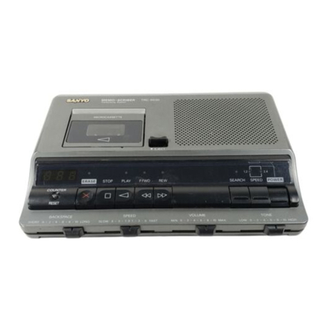
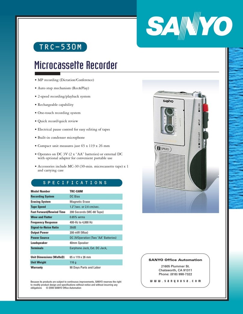
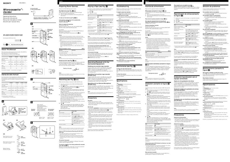
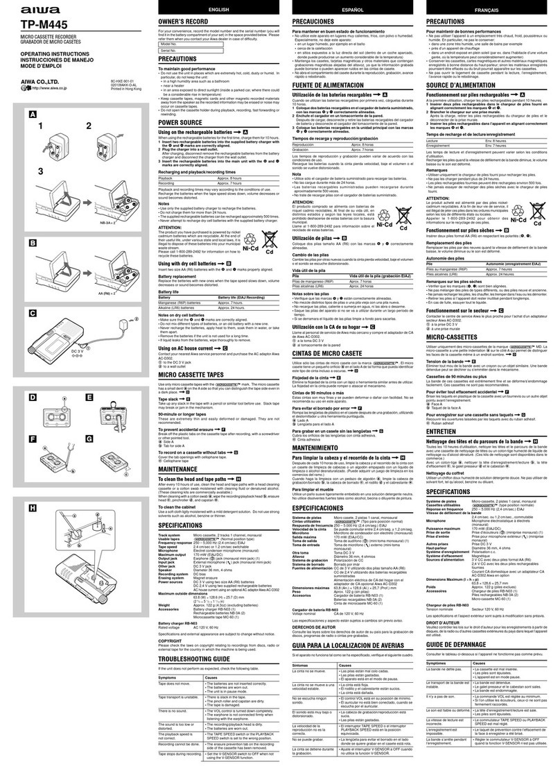
Sanyo TRC-3690 XE User manual

Service Manual
FILE NO.
Mini Cassette Recorder TRC-3690 (XE)
Specifications PRODUCT CODE No.
14260401
Recording system .......... DC bias, 1/2 track Output power ......... 200 mW (Max. music power)
Erasing system ............ Magnet Power source ......... DC :3 V, (2size “AA “batteries )
Tape speed (at tape start begin)
Fast forward time ...........
Rewind time ...............
Wow&flutter ..............
Cue Tone Signal ............
Warning Tone Signal ........
Frequency response .........
S/N ratio ..................
3.09 cmlsec .*5“/0 Terminals ............ Earphone jack :8 ohm
620 sec. (with MC-40N) Ext. DC jack
135 sec. (with MC-40N )Ext. MIC jack :3.3k ohm
1.5 %RMS Dimensions .......... 66 (W) x135 (H) x29 (D) mm
150 Hz Weight .............. Approx. 185 g (without batteries)
1.2 -3.2 kHz
400-4,000 Hz Specifications subject to change without notice.
28 dB
REFERENCE No. SM580439

REMOVAL AND INSTALLATION u
GENERAL REMARKS
●
●
●
a.
All wiring should be returned to the original position after work is completed.
Before adjusting the mechanism of this unit, wipe the tape contacting surfaces clean as well as
the contacting surfaces of the driving parts with acotton swab or asoft cloth soaked in alcohol.
Trouble may occur because of oil and grease stains.
Handle the belt carefully because grease easily attaches to it.
Then check the used rubber parts.
If the rubber has deteriorated or is scratched, replace the parts with new one.
TOP LID b. AMP. P. W. BOARD &MECHANISM
d&
lb
c. WIRING LAYOUT
●Arrange the wiring as shown in the figure.
/WHITE-
\BLuE-
(
ORENGE-
BLUE-
SVJ;;CDH
IBATTERY LEAD
I
~
RED
WHITE
riB”cK
*’
?)==4
RED ~ ,’,:
l’,+’;: BLUE
MHITE
BLACK
-
-1-

ADJUSTMENTS
Measuring instructions, tools (6) TEST TAPE, HEAD AZIMUTH (7) TEST TAPE, MOTOR SPEED
(1)
(2)
(3)
(4)
(5)
a.
(a)
AF VT~M ●Using tape :Mini-cassette tape of ●Using tape :Mini-cassette tape of
FREQUENCY COUNTER 18 pthick( A-BEX SSC-1 584, etc.) 18 pthick( A-BEX SSC-1 582, etc.)
OSCILLOSCOPE ●Recording signal :4 kHz ●Frequency of Recorded Linear Sweep
DC POWER SUPPLY ;3.0 V●Recording Lebel :-10 dB Singal :4,575-3,925 Hz
DUMMY LOAD, 4ohms ●Recording Tape speed :4.75 cmlsec. ●Recording Lebel :-10 dB
●Recording Time :84.5 sec
●Recording Tape speed :4.75 cmlsec.
HEAD REPLACEMENT AND AZIMUTH ADJUSTMENT
Head replacement E. HEAD R/P HEAD
●After replacement, demagnetize the heads by using aWHITE
head eraser.
EHE~~gDGi,[i~=~+A~IEDD
●Be sure to clean the heads before attempting to make any
adjustments.
(b) sENSOR BLACK
(1)
(2)
(3)
(4)
b.
(1)
(2)
(3)
c.
Head azimuth adjustment
Load the test tape (A-BEX SSC-1 584,, etc. )
for azimuth adjustment.
Playback the test tape..
Use across-tip (+)screwdriver to turn the screw for azimuth
adjustment so that the outputs maximized.
After completion of the adjustment, use threadlock (TB-1 401 B)
to secure the azimuth adjustment screw.
MOTOR SPEED ADJUSTMENT
Load the test tape (A-BEX SSC-I 582,, etc.).
Playback the test tape..
Use across-tip (-)screwdriver to turn the P501 to adjust
so that the frequency counter becomes 3,000 Hz.
CHUCKING THE MECHANISM TORQUE
(1) Playback mode .... more than 40 g-cm
(2) Fast Forward mode .more than 45 g-cm
(3) Rewind mode . . . . . . more than 40 g-cm
PARTS LIST
HEAD AZIMUTH ADJ.
CAUTION: Regular type resistors and capacitors are not listed. To know those values, refer to the schematic diagram.
PACKING &ACCESSORIES ELECTRICAL PARTS
Ref. No. Part No. IDescription Ref. No. Part No. Description
I614 268 2050 ]CARTON CASE 51 I620 003 3244 MICROPHONE
620 208 0512 PAD,STYROFOAM
620 208 0505 PAD, PLAIN FPC, LED P.W.BOARD
620 210 1453 POLY COVER Ref. No. Part No. Description
620 148 6216 POLY COVER 62 620 207 0353 FPC, LED
614 268 2135 INSTRUCTION MANUAL D201 407 094 8705 LED SLN-21ORC
620 208 7788 CARRYING CASE 620 125 0114 SHEET
-2-

EXPLODED VIEW (CABINET &CHASSIS )
o
1- -;’
-
w
h-yc)l
-3-

w
:ABINET
Ref. No.
1
2
3
4
5
6
7
8
9
10
11
12
13
14
15
16
17
18
19
20
21
&CHASSIS
Part No.
620 207 2296
620 206 5298
614 268 1503
620 119 7440
620 206 5359
620 139 0469
620 206 5304
614 272 3005
620 208 6163
620 112 9526
620 206 5335
620 206 5243
620 206 5236
614 268 1688
620 108 4825
620 124 5691
614 268 1589
411 086 1803
620 139 3798
614 272 3029
614 268 1763
620 124 4847
FIXING PARTS
Ref. No.
Yol
Y02
Y03
Y04
Y05
Y06
Y07
Y08
Y09
Ylo
Yll
Y12
Part No.
411 099 0800
620 122 9332
620 122 9004
620 122 6041
620 122 6652
620 122 9004
620 122 8243
411 099 0800
411 099 0800
411 124 6500
412 040 2706
411 019 9401
AMP P.W.BOARD ASSY
Ref. No.
61
Clol
C102
IC101
J1
J2
J3
J4
P501
Q101
Q301
Q302
Q303
Q304
Q305
S1
S2
53
S4
S5
VR101
Part No.
620 206 2945
403 067 7201
403 067 7201
409 149 3307
620 019 2026
620 019 2026
620 020 8512
620 019 1999
620 218 5392
405 000 0904
405 011 8500
405 011 8500
405 031 6708
405 031 6708
405 011 8500
620 206 3508
620 206 3515
620 138 5991
620 016 4467
620 206 5342
620 006 0233
Description
ASSY,DECORATION,MIKE
HOLDER,MIKE
ASSY,LID,CASSETTE
SPACER
STOPPER,LID CASSETTE
SPRING LID CASSETTE
HINGE
CABINET,ASSY,TOP
(WITH SPEAKER)
SHAFT,HANOLE
HAND STRAP
BRACKET-M,SPRING
KN08,SLIDE,RECORD
KNOB,SLIDE,FUNCTION SELECT,
REVIEW/STOP/PLAY/PREVIEW
KNOB,SLIDE,SAFETY
KNOB VOLUME
CUSHION
BUTTON,PUSH,CUE TONE
WASHER SPRING 2X4X6MM
SPRING EARTH
ASSY,CABINET,BOTTOM ASSY
LID,BATTERY
CUSHION,P.W.80ARD MTG.
Description
SCR PAN PCS 1,7X5MM
SCREW,2X1OMM
SCREW
SCREW,2X4MM
SCREW,1.7X3MM
SCREW
SCREW,l.7X3MM
SCR PAN PCS 1.7X5MM
SCR PAN PCS 1.7X5MM
SCR FLT PCS 1.4X4.5MM
SPECIAL SCREW
SCR PAN PCS 1.7X2.5MM
Description
ASSY,PWB,AMP
MT-COMPO 0.033U J 50V
IC LA4165M
lP,JACK,MIC
lP,JACK,EARPHONE
EXT POWER SOCKET
lP,JACK,REMOTE
VR,SEMI 3K N
TR 0TA114YS
TR 2SC1740S-R
TR 2SC1740S-R
TR 2SA933-SR
TR 2SA933-SR
TR 2SC1740S-R
SWITCH,SLIDE,2K-4P-2T,
RECORD/PLAY
SWITCH,SLIDE, 1K-1P-2T,SAFET’
CONTACT SWITCH,FF/REW
TOUCH SWITCH lPIT,INDEX
SPRING,PLATE,MUTE
ROTARY VOLUME C 20K
flECHANISM (TM-T3690-SH]
, . .... ——_—_.. ,
Ref. No. Part No. Description
101 411 015 6800 RING E 1.2MM
102 620 125 1081 WASHER, 1.6X3.5X0.2MM
103 620 126 4722 REEL SUPPLY
104 620 125 1371 WASHER, I.6X4X0.13MM
105 620 082 7935 REEL TAKE UP ASSY
106 620 125 1548 WASHER, 1.7X4X0.25MM
107 620 137 1345 SPRING BRAKE
108 620 129 7737 PLATE BRAKE
109 620 220 3676 SPRING,TENS
110 620 139 0605 SPRING
111 411 015 7609 RING E 1.5MM
112 620 130 0529 PLATE SLIDE
113 620 209 7428 ASSY,MOTOR,3V,0.3W
114 620 124 0498 CUSHION MOTOR
115 620 207 2241 ASSY,CHASSIS
116 620 119 3541 SPACER
117 620 122 6911 SCREW,1.7X4MM
118 620 083 3400 ARM COMPL
119 411 015 6800 RING E 1.2MM
120 620 128 6243 8ELT DRIVE
131 411 015 7609 RING E 1.5MM
132 620 130 1106 PLATE LOCK RECORD
133 620 139 0452 SPRING
134 411 015 7609 RING E 1.5MM
135 620 084 2006 LEVER RECORD ASSY
136 411 000 9304 RING E 2MM
137 411 015 7609 RING E 1.5MM
138 411 016 0203 RING E 2.5MM
139 620 083 9211 PLATE LOCK ASSY
140 620 139 0551 SPRING
141 620 122 6133 SCREW,2X2MM
142 620 125 7922 LUG
143 411 019 4505 SCR PAN PCS 1.4X3MM
144 620 016 4962 LEAF SWITCH,POWER,S1
145 620 137 1086 SPRING SLIDE
146 411 015 7609 RING E 1.5MM
147 620 206 5311 INDICATOR
148 620 122 7536 SCREW,l.7X2MM
149 620 206 5328 PLATE,INDICATOR
150 620 122 6126 SCREW,2X3MM
151 620 137 2861 SPRING
152 620 023 3514 ERASE HEAD,HO-2
153 411 015 6800 RING E 1.2MM
154 411 015 7609 RING E 1.5MM
155 620 130 0543 LEVER ERASE HEAD
156 620 125 1371 WASHER, 1.6X4X0.13MM
157 620 127 3113 GEAR IDLER
158 620 125 3399 WASHER
159 620 137 1017 SPRING AZIMUTH
160 411 088 6509 WASHER F 2X4,3X0.4MM,
R/P HEAD
161 620 202 5261 HEAD,R/P,2T,HD-l
162 620 122 6102 SCREW,2X3MM
163 614 226 9510 ORDER SCREW
620 123 7658 SHEET,MOTOR MTG.
620 124 4847 CUSHION,MECHANISM CHASSIS
MTG .
)
-4-
EXPLODED VIEW (MECHANISM )
101–~
lo2–~
&
e—lot
&_lo2
103- ‘
104+ Qb -105
107-w?% &-1o6
108- ~ I
%A
y‘%+)9
153- I~,,+ W+o
+
152- 162-w 8-’63 L
fiJ
‘-. *-111
161-‘-,’~ /“)% -112
A
11644
I-116
117-J31
4-117
138-+ &-137 ‘\
Q9-136
J
4$$?
118-
/.
6119-J
A
135- &O’
1,
-
,33_aji ‘f
J?j?
--132
,31_JlH31
–b-
W

(
E.I. MF&&l
T
1 t I~1 r’S&Y
:
1
%’ OQ+A!114Y5
------------- ,
J. o
?
J%TE
,—
%
00 0 0/.8 /.8 0
.——
/. o0. // -T /. .r2 /.8 /. 8
u-c
---------------- J
CC3.OV -I
*
~“2J”
I
m
1L
S1-1
H02- 1
ERASE HEAO
X-J
SWITCHES
,, IS1 IREC/PLAY wIPLAY I
1s3 Iff/REwsn IKFF]
LaTN+ END SENW? A
-iw%
L-J
!%4
HO1-2
INOEX HEAO
‘i% !?%Iac~
-

WIRING DIAGRAM -
[1
INDEX
SWITCH
-
Slool
POWER
SWITCH
/
7
—.
11
s*O
Jan. /’91900KMKM Printed in Japan
-7-
SANYO Electric Co., Ltd.
Osaka, Japan
Table of contents
Other Sanyo Microcassette Recorder manuals

Sanyo
Sanyo TRC-3640 User manual

Sanyo
Sanyo TRC-6300 User manual

Sanyo
Sanyo TRC 8080 - Cassette Transcriber User manual

Sanyo
Sanyo M1110 User manual

Sanyo
Sanyo MEMO-SCRIBER TRC-6030 User manual

Sanyo
Sanyo M1112 User manual

Sanyo
Sanyo MCD-S730F User manual

Sanyo
Sanyo TRC540M - Auto Stop Microcassette Recorder User manual

Sanyo
Sanyo TRC-8800 - Cassette Transcriber User manual

Sanyo
Sanyo 530M - TRC Microcassette Dictaphone User manual