manuals.online logo
Brands
  1. Home
  2. •
  3. Brands
  4. •
  5. Sanyo
  6. •
  7. Projector
  8. •
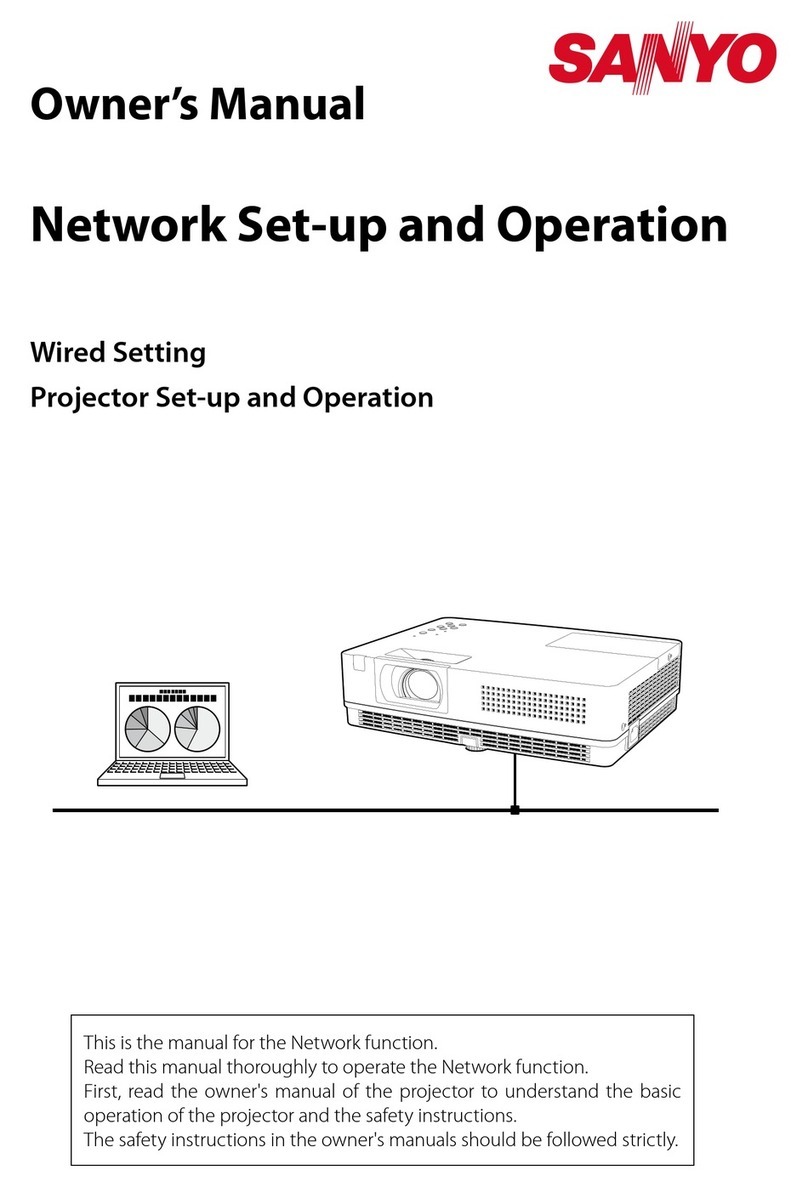
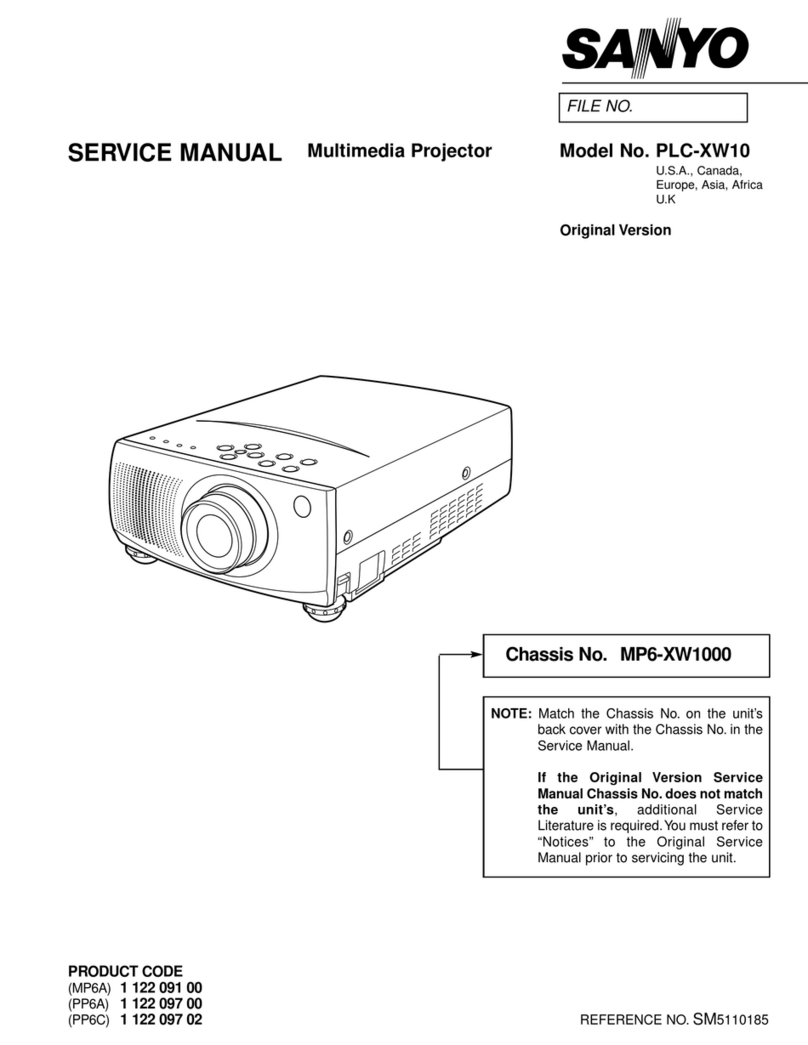
  9. Sanyo PLC-XP18N User manual

Sanyo PLC-XP18N User manual

Other manuals for PLC-XP18N

2

This manual suits for next models

2

Other Sanyo Projector manuals

Sanyo PLC-XF12N User manual

Sanyo

Sanyo PLC-XF12N User manual

Sanyo PLC-XC50A - 2600 Lumens User manual

Sanyo

Sanyo PLC-XC50A - 2600 Lumens User manual

Sanyo PLC-XU305A - 3000 User manual

Sanyo

Sanyo PLC-XU305A - 3000 User manual

Sanyo PLC-400N User manual

Sanyo

Sanyo PLC-400N User manual

Sanyo PLC-XU40 User manual

Sanyo

Sanyo PLC-XU40 User manual

Sanyo PLC-XF70 User manual

Sanyo

Sanyo PLC-XF70 User manual

Sanyo PLC-XU105 User manual

Sanyo

Sanyo PLC-XU105 User manual

Sanyo PDG-DWL100 - WXGA DLP Projector User manual

Sanyo

Sanyo PDG-DWL100 - WXGA DLP Projector User manual

Sanyo PDG-DWT50L - WXGA DLP Projector User manual

Sanyo

Sanyo PDG-DWT50L - WXGA DLP Projector User manual

Sanyo PLC-EF10N - SXGA LCD Projector User manual

Sanyo

Sanyo PLC-EF10N - SXGA LCD Projector User manual

Sanyo 5500 - SCP Cell Phone Setup guide

Sanyo

Sanyo 5500 - SCP Cell Phone Setup guide

Sanyo Think GAIA PLC-WXU700 User manual

Sanyo

Sanyo Think GAIA PLC-WXU700 User manual

Sanyo PLC-XE30 User manual

Sanyo

Sanyo PLC-XE30 User manual

Sanyo EF10NZ - SXGA LCD Projector User manual

Sanyo

Sanyo EF10NZ - SXGA LCD Projector User manual

Sanyo PLC-WL2503 User manual

Sanyo

Sanyo PLC-WL2503 User manual

Sanyo PLC-XW20 User manual

Sanyo

Sanyo PLC-XW20 User manual

Sanyo PLC-WL2500 Installation manual

Sanyo

Sanyo PLC-WL2500 Installation manual

Sanyo PLC-ET30L User manual

Sanyo

Sanyo PLC-ET30L User manual

Sanyo PLC-XU355A - 3500 User manual

Sanyo

Sanyo PLC-XU355A - 3500 User manual

Sanyo PLC-WU3800 Installation manual

Sanyo

Sanyo PLC-WU3800 Installation manual

Sanyo PLC-WM4500 User manual

Sanyo

Sanyo PLC-WM4500 User manual

Sanyo PLC-XL51 - 2700 Lumens User manual

Sanyo

Sanyo PLC-XL51 - 2700 Lumens User manual

Sanyo PLC-EF12B User manual

Sanyo

Sanyo PLC-EF12B User manual

Sanyo PLC-XF30 Quick start guide

Sanyo

Sanyo PLC-XF30 Quick start guide

Popular Projector manuals by other brands

Eiki LC-X985 Specification sheet

Eiki

Eiki LC-X985 Specification sheet

InFocus LitePro 610 quick start

InFocus

InFocus LitePro 610 quick start

Epson EH-TW5900 datasheet

Epson

Epson EH-TW5900 datasheet

FOREVER MLP-100 manual

FOREVER

FOREVER MLP-100 manual

Toshiba TDP-MT8U Specifications

Toshiba

Toshiba TDP-MT8U Specifications

Mitsubishi XD500U specification

Mitsubishi

Mitsubishi XD500U specification

Kodak Ektapro 3020 Illustrated parts list

Kodak

Kodak Ektapro 3020 Illustrated parts list

Toshiba TDP-EW25U Specifications

Toshiba

Toshiba TDP-EW25U Specifications

Barco iQ PRO G500 supplementary guide

Barco

Barco iQ PRO G500 supplementary guide

NEC Showcase Series HT1100 user manual

NEC

NEC Showcase Series HT1100 user manual

Philips LC1341 user guide

Philips

Philips LC1341 user guide

Epson PowerLite 1266 user guide

Epson

Epson PowerLite 1266 user guide

MAGINON DLP 1400S user manual

MAGINON

MAGINON DLP 1400S user manual

Toshiba TLP-380 owner's manual

Toshiba

Toshiba TLP-380 owner's manual

Philips PicoPix PPX2480/EU user manual

Philips

Philips PicoPix PPX2480/EU user manual

Hitachi CP-X605 Series Specifications

Hitachi

Hitachi CP-X605 Series Specifications

Optoma TW1692 user manual

Optoma

Optoma TW1692 user manual

Kodak EKTAPRO instruction manual

Kodak

Kodak EKTAPRO instruction manual

manuals.online logo
manuals.online logoBrands
  • About & Mission
  • Contact us
  • Privacy Policy
  • Terms and Conditions

Copyright 2025 Manuals.Online. All Rights Reserved.

SERViCE
MANUAL
Mu^-med!a
Projector
S4^o
F/^
MO.
MODEL
NO.
PLC-XP18N
(U.S.A.
.Canada)
PLC-XP18E
(Europe,
Asia,
Africa,
M.E.)
PLC-XP18B
(U.K.)
ORIGINAL
VERSION
Chassis
No.
MH6-XP18NOO
PLC-XP18EOO
PLC-XP18BOO
NOTE:Match
the
Chassis
No.
on
the
unit's
back
cover
with
the
Chassis
No.
in
the
Service
Manuaf.
tf
the
Ortgfnai
Version
Service
Manua!
Chassis
No.
does
not
match
the
unit's,
additional
Service
Literature
is
required.
You
must
refer
to
"Notices"
to
the
Original
Service
Manual
prior
to
servicing
the
unit.
Give
complete
"Chassis
NO."
for
parts
order
or
servicing,
ft
!s
shown
on
the
rating
sheet
on
the
cabinet
of
the
Projector.
Specifications
Disassemblies
Mechanica
Optical
urn
LCD
pane)
Assy
tamp
Safety
Instruc
Circuit
Protec
Troubleshooti
Waveforms
-
Alignment
Prc
Service
ad
Electrical
a
Focus
adju.
Convcrgen
Product
Code
CONTENTS
and
Replacement
Procedures
disassemblies
--....-.-...--
t
disassemblies
-.........-.--
replacement
.........
replacement
..----.....-..--
ions
""..-..
ions............--.-....."
ng
........................
ustments
.......-..--.
djustments
.."--......-""
stments
--.-..""........"
ce
adjustment
."--......."
1
12207740
:
PLC-XP18N
1
12207840
:
PLC-XP18E
1
12207842
:
PLC-XP18P
................
^
.............
3^17
.............
9^14
...............
15
............^6-^7
...............
^g
...............
19
............
20-27
............
30-43
............
31"-32
...............
^o
MH6AA
PH6AA
PH6CA
mtegratoT
lens
adjustment
---..-.----.......
Relay
lens
adjustment
-..----......""..---
Polarized
glass
adjustment
.--.....--.-..---.
CPU
input/output
port
functions
---...-.........
Maintenance
- - -
---..-..--........."----....-
Notes
on
schematic
diagram
........"---.....-
Parts
-List
..................................
Cabinet,
Chassis
and
Optical
patts
!ist...----..
Electrical
parts
list
...".......----..---....
Parts
location
and
PWB
pattern
diagrams
---....-
Block
diagram
and
Low
power
distribution
"
"
- -
-
Schematic
diagrams
..........................
REFERENCE
----------
41
..........
43
.......
48-49
.......
5^51
.......
52-79
.......
59-79
..........B1
WO.SM5110206
PLC-XP18N
PLC-XP18E
TECHN)CAL
SPEC)F)CAT)ONS
TECHN)CAL
SPEC!F)CAT!ONS
PmtteMfTyp*
NM—tM^tW'MtD)
tMWtt^t
LO)^'*")MtM'
MM^Xfc<M)Mt<
C«)u<)t)"MM
tut)t)t)eR^^*f
^Mtte^Mtt^Btt'fDhtM*))
f^^tan'J^'
Hoftt.XtM
mottttMett
Tttfo^Mtttme*
Pt^at^LtXt^
jtV)nt^tJ**t
CMXtMtM-'nptttJtdtt
Cetxpt^ftMpM^A
CMnp^Me'nf^.'-*'
0)htf*tatt
XXttMatpt-tM'
tnx.t*
HH^ttfto
jM)tt.t«.!)t
^Mt^'
t^)ttC«titM))t«M
Op-^wTtMf^tXM
^tefOtttTttf'HtM
n—ofCemMTuMmM't'
MuM^ttttPn^eMt
'a.7't:7tnm)'E.7'(t*6.6mm)tte.:'f<'!.Emm)
'6.:^tn«.9k^
'^'TtTAettMMtMtM)*
!t3))tn*H
MM^e(7M^Mt'.OM'7M)t3}
t<!o)o't^ttmjPAL.MC*M.MTaC.MTMM.O.)'^L-MtndML-N)
^m<.
16
-
'M
KH^^t^t:.
M
-
'<M
H!
*t'^Ntfem31')o<M'
F'^-^.Htn.wthh-M.4nm-M.t'm'MofccmMttoem
tMT\t^t
4.t-(t.^)-47^<14.4m)
MOwMttyp.
aC*^pt3.:ttt.(VMt^Autft.atnau.(^.ChM).Ct^)
[Va*)HDattTtm'n*)'a.mmf*'(OonMpo[a'!'
(VOA)MOt'eT*m*^
MntNt^oT^p.
j.t
Exr.atM-^jM'fa^*ti)ti
'MT.MSMm)(R-mj.2tMt)RMSfT^mo%)
Up
tea'
IM-1MWC.MMH.
MAft^.A^f.)
t-C^-C(4t-F-M-F)
-'<^-M-C{K'F-t<C'F)
i^^^^L^^^X^^
t^)*etefT)^
D)t)MtXfon*[W]tH^D)
MtW*^t
t.eo^ttmtfmttn
HMXttfefPOMX
CetCM't^ffM
OMM)t<t)t^()Mney
flatten
)'H<N*«MfC<«Ban^
Mat^MttttM^aMfon
f^tt«M)^f
ThMwDtttMM
Pt^teWenL'ttxt)
^)^J^.
OMttpaMftntM
*)(*);
CemfHt^OtttMtJtttft
C<Mpt)t*rMe)^Jt<<(t
0)h^*«*
MHxtpt-Mr
)-^n-^-.*<)""m"<
<Mt^.
MM^CeM<)Mt^M
Op'!t)'^T*<MMMtHt*
tten)BtTto^n)H«
it^^.CMMT......^
.
MuM-nttttt^t^M
272
mm
<
'<t.6
mm
<
412-6
mm
M^
t.yTFTAetttf^MtM)*
*3fM^*
2.9M.Met7W.<3!(t.aM'7M)!'^
tcoUxft^ttmfP^L.iECAM.'^SC.
NTaC4.43.ML-MtttjRH.-H)
^t)me.'e-tMKHt.V.on).M-")OHz
MhttttNtttm3t'M40^
tMTV!htt
Fl.t-n'Mt^t-M.tmm-tMmmHeMtMmtMtM^
'.4m-t*.4^
MOMMttfp.
tMMH*p't)t^-MOte))ft
{VQA)HDenTtm)tif!tt.D<mt^tCcn)M)pe^)t:
(VaA)
HM
)t1tnntn'
MMSXtto^i;^
EX^.Sp^t^J^fStmom
tm;we^«)(Htt^L),2'MNHMafr^.D.'e%)
upMe*
MO-MOV*c.NMaHtfMaa.fPUmM'EM'i)E)
ne-1ZCVtC.MMm{ModOPLC-XM1^tP1t)
t.tA[Mtn.A^M)Mt^)'^&^<M'EM't)e
MA<MM.)^p^.)Mc<MPLC-)(P2I/)(''^
M:-3t^:f<t'P-t6^)
-)e^-te^:tt4'F-)<e^)
Wt*)tttntmottC<M)M<)*hLtttfBt^!C't<t
n
Ltttt)
LttOfttodtt
hM.
t
X
dtOentd
tnd
mtnu^oWtd
M
m*t<
t^f
u.L.
t*M^
PLC-XP18B
TECHN)CAL
SPECtF)CATfONS
PKt*ttcrTtP*
NMtM^n)f[W!<H)tp)
H^W*t^
[^&httMH^^
^«''t!fOtP6ttt<t
CoteMT^tttOt
tM)mi)f^)fMo)t«M]'
thr^nf)!-*'
^'^
)MM
fOMttaOtf)
HMtMnMtt*M)t)t)en
PM^MMattLMt
Tt^wOtttMe*
'^*eeanU)tntt
^tt^UtJtCttt
CM«))Mttf)t)pumc'Ct
CamptttMOt^mmf*
CM^ot^Jht^topotJ^*
OtfMf^ct
ButttttapM**t
'^9''a.tX«t<HM)MMMtnt
^Mt^t
'^MfeenMmptfon
OptfOt^Tt-ptf^uf*
TMfr'9*
T<«^tr*tjrt
'^^.^MT^^,
HtJM^nttttPn^tetor
27ZmmtMMmn't<'Mmm
M^
'.a'TPTAMhthXmtttn)*
Of^ttt
e.3ae^M{7M.<^m.OM)t7M)0)
ea!tmr.^ttm(f^MO*M.MTac.MTaC<.4a.ML-UtndP)U.-M)
H^nc.t6-'(mKHz.V^^M-'0(!Ht
*<ttt)^tthcm:1'M*M'
*MTVh.tt
F'.t-:.''^.^M.4mm-eM^Hota.mom.ndb=u.
'.<m-)4.<m
aHwMW
PWOn01^)t3!?t*ttftM*o.A))*)R'ndL}.tY.Ch<Pt).CKPf)
<nJD)M4ph(S-VM*<H!tt
(MA}HCei6Ttm<n^t:.MMt[4n(C<ntMtMn))t:
fWA}HDe'6TwmM
MMB<tftoT^)ti;:
EXT.
St^tHttJttf
(attMO)
x
t
'HT.
9P.
8)t<*e
(R
Md
U.:
x«)
RMS
(T^.[11(<%)
up'c.e'
MO.MovAC,6n<em
1.tA(Mt)LAmpttt)
t-c-M'c(4i'F-es'H
-tO^-M^^-F-KO-F)
^^T^^^^^^^^u
Mechanjca)
D!sassemb)ies
Mechantca)
disassembte
shouid
be
made
following
procedures
in
numencai
order.
Fo!!owing
steps
show
the
basic
procedures,
therefore
unnecessary
step
may
be
ignored.
Cautton:
The
parts
and
screws
shouk)
be
piaced
exactiy
the
same
position
as
the
ongina)
otherwise
)t
may
cause
toss
of
per-
formance
and
product
safety.
1.
COVER
TOP
REMOVAL
1)
Siide
the
tocking
iever
in
the
direction
of
the
arrow
by
using
s!ot
screwdriver
(Fig.t)
and
ifft
up
the
cover
siight!y-
2)
insert
two
'tmm
stot
screwdrivers
to
the
stots
of
the
cabinet
top
at
the
same
time.
Thm
them
in
the
arrow
direction
gentty
to
lift
off
the
cover
top
upward.
Note:
Be
carefui
not
to
damage
the
cabinet
finish
when
removing
it.
COVER
TOP
2.
CAB!NETTOP
REMOVAL
1)
Remove
4
screws
on
side
cabinet
and
1
screw
on
rear.
2)
Grasp
the
two
stdes,
puii
the
cabinet
top
upward
and
remove.
CABINET
TOP
3.
CABINET
FRONT
REMOVAL
1)
Remove
2
screws
on
cabinet
front
bottom.
2)
Grasp
the
two
stdes.
putt
the
cabinet
front
forward
and
remove.
RC
Front
unit
5.
LED
UN!T
AND
SPEAKER
REMOVAL
1)
Retease
two
hooks(A)
and
pu))
out
the
LED
unit.
2)
Remove
4
screws(B)
and
then
remove
the
speakers.
6.
LAMP
BALLAST
BOX
AND
FAN
(FN905)
REMOVAL
1)
Remove
2
screws(A),
2
screws(B)
and
2
screws(C),
and
then
pu)!
the
tamp
ba)!ast
box
upward
and
remove.
2)
pu))
the
fan
(FN905)
upward
and
remove.
—5—
7.
OPDCAL
UN!T
AND
FAN
(FN904)
REMOVAL
f)
Remove
6
screws(A)
and
then
pu!!
the
optica)
unit
upward
and
remove.
2)
Remove
2
screws(B)
and
remove
the
fan
(FN904).
8.
POWER
SW!TCH
UN)TAND
FAN
REMOVAL
1)
Remove
5
screws
and
then
pu)!
the
power
switch
unit
upward.
2)
Remove
2
screws
and
remove
the
fan(FN906).
6—
9.
FAN
(FN901,
PN902),
A!RDUCT
REMOVAL
-))
Remove
4
screws(A)
and
pu)t
the
airduct,
fan
(FN901).
and
fan
(FN902)
upward.
2)
Remove
4
screws(B)
to
dtsassembte
the
airduct
assemMy.
Fan
(FN901)
10.
POWER
UN!T
HOLDER
REMOVAL
1)
Remove
6
screws,
pu)[
the
power
unit
hofder
upward-
Power
Unit
Hokier
11.
POWER,
SUB
POWER
AND
AUDtO
UN)T
REMOVAL
1)
Put)
the
sub-power
and
Audio
unit
upward.
2)
Remove
7
screws
and
pu!!
the
power
unit
upward.
Audio
unit
HtC-A
Unit
Power
Uni
H!C-B
Unit
Power
Unit
Hotder
12.
LAMP
BALLAST
UN!T
AND
FAN
(FN903)
REMOVAL
1)
Remove
2
screws(A)
and
remove
the
shieid
cover.
2)
Remove
4
screws(B)
and
puif
the
iamp
baitast
unit
upward.
3)
Put!
the
fan
(FN903)
upward.
Lamp
Battast
Box
Remove
the
cabinet,
cabinet
front,
main,
video
and
A/V
unit
fo!kw-
ing
to
steps
2
to
4
of
"Mechanical
Disassembles".
1.
LENS
ASSY
REMOVAL
1)
Remove
4
screws
and
remove
the
tens
assy.
F!g.1
2.
RELAY
LENS
AND
tNTEGRATOR
LENS
AND
POLARIZED
GLASS-)N
R,
G,
B
REMOVAL
1)
Remove
2
screws(A)
and
then
pufi
the
relay
tens
upward.
2)
Remove
2
screws(B)
and
then
puf!
the
integrator
iens
upward.
3)
Remove
each
screw(C)
and
then
pu!!
the
pofahzed
giass-in
R,
G,
B
upward.
Polarized
Gtass-!N
(G)
Potarized
Gtass-)N
(R)
Poiarized
Giass-iN
(B)
9—
3.
POLAR)ZED-GLASS-OUT
R,G,B
REMOVAL
1)
Remove
ass'y-LCD-Panefs.
R/G/B
2)
Remove
4
screws
and
then
put)
the
Ass'y-
po)arized-g!ass
upward.
ASS'Y
POLAR)ZED
GLASS
3)
Remove
the
Stopper-FLT-RGB
4)
Remove
the
po[arized-g)ass-out
R,G,B.
Potarized
gtass-out
(B)ue)
Mounting-Prfsm-CR
*
:
F!)m
side
Poiarized
g^ass-out
(Green)
Po)arized
g)ass-out
(Red)
Poiarfzed-gt.iss-nut
R,
G
!tnd
B
Hre
not
med
m
'i!)me
pat'ticutar
inodet',.
10