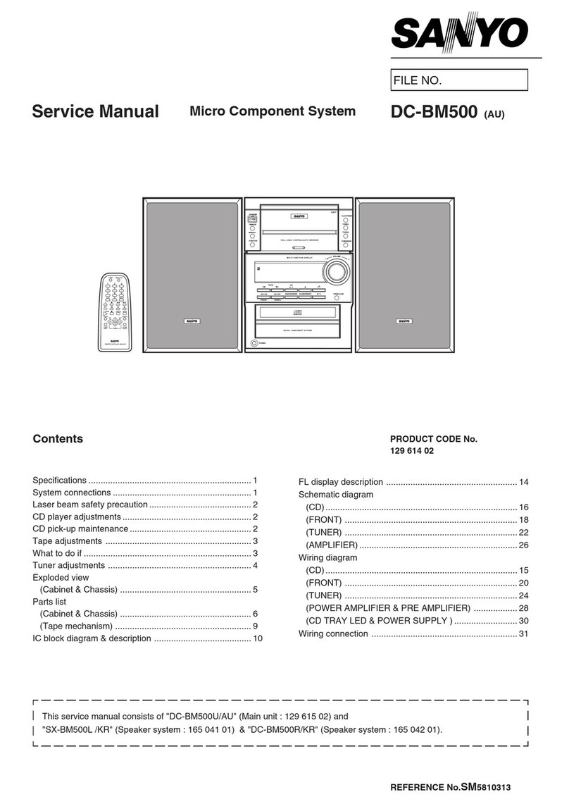
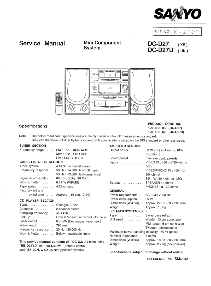
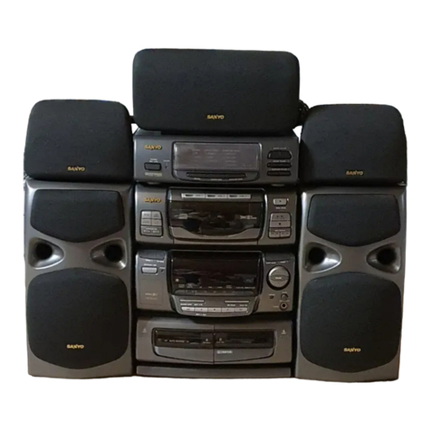
Sanyo DC-F170 User manual

m
Service Manual Mini Component
System
....
Specifications
TUNER SECTION
Reception frequency .FM :87.5-108.0 MHz
MW :522-1,611 kHz
CASSETTE DECK SECTION
Track system . . . . . . . 4track, 2-channel stereo
Frequency response . . 80 Hz -13,500 Hz
Signal to noise ratio . . 50 dB
Wow &Flutter . . . . . . 0.15 %(WRMS)
Tape speed . . . . . . . . 4.75 cmlsec
Fast forward and
rewind time . . . . Approx. 110 sec. (C-60)
CD PLAYER SECTION
Type ..............
Channels ..........
Sampling frequency . .
Pick-up ............
Laser output . . . . . . . .
Wavelength . . . . . . . .
Frequency response . .
Wow &Flutter . . . . . .
Changer, 3-disc
2-channel stereo
44.1 kHz
Optical 3-beam semiconductor laser
0.6 mW (Continuous wave max.)
790 nm
20 Hz -20,000 t+Z
Below measurable limits
This service manual consists of “’DC-F170U”( main unit ),
“RB-D9” (remote control )&“SX-F170” (speaker system)
DC-F170 (AU)
u’
.. .
PRODUCT CODE No.
129 502 05
AMPLIFIER SECTION ‘“””’”‘-‘“ ““’‘--” ‘- “’”
Output power . . . . . . .
Inputs . . . . . . . . . . . . .
outputs ...........
15WX2
(at 4ohms, 10% distortion )
VIDEO :400 mV /50k ohms
SPEAKER :4 ohms
Power requirements . .
Power consumption . .
~mensions (WXHXD) .
Weight . . . . . . . . . . . .
SPEAKER SYSTEMS
Type ..............
LJnit used . . . . . . . . . .
PHONES :8-32 ohms
AC :230-240 V, 50 Hz
45 w
Approx. 270 x300 x293 mm
Approx. 5.7 kg
2way bass reflex
Woofer: 12 cm cone type
Tweeter :piezoelectric
Maximum power-handling capacity 25 W(peak)
Nominal impedance . . 4ohms
Dimensions (WXHXD) .Approx. 180 x300 x207 mm
Weight . . . . . . . . . . . . Approx. 1.8 kg (per speaker)
Specifications subject to change without notice.
REFERENCE No. SM580751

. ... ... .. ... ... .
CONTENTS
.,.. .. . . . ... i
.
..,,-
SPECIFICATIONS . . . . . . . . . . . . . . TOP
LASER BEAM SAFETY PRECAUTIONS .1
BEFORE USE OR TRANSPORTATION .2
WHAT TO DO IF . . . . . . . . . . . . . . . . . . 3
REMOVAL AND INSTALLATION ...... 3
TUNER ADJUSTMENTS . . . . . . . . . . . . 5
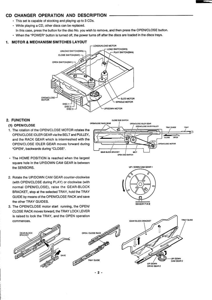
CD CHANGER OPERATION
DESCRIPTION . . . . . . . . . . . . . . . . . . . 6
CD MECHANISM REPLACEMENT .... 10
CD MECHANISM ADJUSTMENTS .... 15
CD PMYER ADJUSTMENTS ....... 17 _, #
TAPE DECK ADJUSTMENTS ....... 19
EXPLODED VIEW . . . . . . . . . . . . . . . . 21
PARTS LIST . . . . . . . . . . . . . . . . . . . 22
IC BLOCK DIAGRAM &
DESCRIPTION . . . . . . . . . . . . . . . . . . 27
SCHEMATIC DIAGRAM ............ 36
WIRING DIAGRAM ............... 38
IC &TRANSISTOR VOLTAGES . . . . . . 56
LASER BEAM SAFEN PRECAUTIONS
.Pick-up that emits alaser beam is used in this CD player. ..
CAUTION :
USE OF CONTROLS OR ADJUSTMENTS
OR PERFORMANCE OF PROCEDURES
OTHER THAN THOSE SPECIFIED
HEREIN MAY RESULT IN HAZARDOUS
RADIATION EXPOSURE 1“
LASER OUTPUT ..... 0.6 mW Max. (CW)
WAVELENGTH . . . . . . 790 nm .
. ..
!
ICAUTION-INVISIBLELASERRADIATIONWHENOPENAND I
INTERLOCKSDEFEATED.AVOIDEXPOSURETOBEAM.
ADVARSEL-USYNLIGLASER STR~LING VED ~BNING, NiiR
SIKKERHEDSAFBRYDERE ER UDE AF FUNKTION. UNDGAUDS HTELSE
FOR STRALING.
VARNIN6- OSYNLIG LASER STRALNING NAR OENNADEL AR OPPNAD
OCHSPiiFtR ~R URKOPPLAO. STR~LEN AR FARLIG.
VORSICltT -UNSICHTBARE LASERSTRAHLUNG TRITT AUS. WENN
]IDECKEL 6EOFFNET UNOWENN SICHERHEITSVERRIEGELUNG I
IIUBERBRiiCKT lsT. NICHT, oErdsTRAHL AUSSETZEN.
VARO! Avattaessaiasuoialukitusohilettaessaoletalttiina
nakymtitliimalle la;era~t~ilylle. Ala katso ateeseen.
-1-
A
.. . . . . . . i
“. .-
.
BEFORE USE OR TRANSPORTATION
(1)
(2)
(3)
(4)
(5)
(6)
;)
(2)
“’y
When earring the unit, be sure to remove A
#
any discs which may be inside. -. .
Press the POWER “OFF”. (~) STANDBY INDICATOR
qOPEN /CLOSE
x
\c)
b
\
CD mechanism :Moving stan
CD mechanism :Home position
The STANDBY indicator “lights”. (Q)
Then unplug the power cord from the AC outlet.
Before use
Remove the shipping screw from the rear of
the unit. (@)
This screw is used to secure the CD mechanism
during shipment and should be retained for
the future use. (@)
SHIPPING SCREW.”’ GREEN ARROW
(412 055 5204) “’
CATTION LABEL
(614 286 4159)
;)
(2)
(3)
(4)
POWER
o
Before transportation
Turn on the power and remove all discs from
the unit. (@)
Turn the POWER OFF. (@)
The STANDBY indicator lights.
Then unplug the power cord from the AC outlet.
Reinstall the shipping screw.
...........................................................................
:●IMPORTANT!
:Before use remove this shipping screw.
~The removed screw should be retained by
;reinstalling the screw to the point indicated green arrow. ~
. . .... . .. ... .. .. .. . .. ........ . . . . ... .... ... . ... . .. . .. . .... . ...... . .. .... .. .. .... .. .. ... .. ..... ...
-2-

..... . . . w
WHAT TO DO IF
If the operation of the unit or display is not normal,
or you wish to clear the contents of the memory.
1. Disconnect the power cord’s plug from the
electrical outlet.
2. Press the RESET button for at least 20 seconds.
3. Connect the power cord.
4. Press the POWER button to turn the power on. m
[gjj---”-” -..:: ..!?.5’.
-.
am% w
..”
D
REMOVAL AND INSTALLATION
“e
o
●
●
I
e
a.
(1)
(2)
(3)
f
b.
(1)
(2)
(3)
(4)
Press the “POWER” button and check that the STANDBY LED lights.
“\
P
Disconnect the power cord’s plug from the electrical outlet. ./:
All wiring should be returned to the original position
after work is completed.
First have ready many the new FIXERS (61 4129 2496)
be
f\”
for replacement.
Arrange the lead wires so that they are not near the heat sink. &
‘+\\\\\A
CABINET .:
Remove the 10 rear panel mounting screws. (0)
Press the STOP/EJECT Button.
Open the cassette compartment lid. (@)
TAPE AND
Remove the
Remove the
Remove the
Remove the
\/l/&l
9
3
-3-

ii
.
REMOVAL AND INSTALLATION
c. POWER TRANSFORMER #
(1) Removal the2shield cover mounting screws.(@) -.
(2)
(3)
......
Removal the AC power socket mounting screw. (@)
Remove the 4power transformer mounting screws. (@))
r
.
d
/
&
/
.8
/>
l-. .
‘h /3 /
/-
.“
.“
/’
,,”
d. CHASSIS
(1) Removal the 3TUNER, AMP. &CD P.W.Board mounting screws. (0)
(2) Removal the TUNER, AMP. &CD P.W.Board. (@,@)
(3) Removal the FRONT P.W.Board. (@,@) 4
(4] Removal the 2CD mechanism mounting screws. (@) n
—.
3
l!-
P.W.B
l—
@%H
7
,..
-4-

TUNER ADJUSTMENTS
a.
-
Use aplastic screw driver for adjustments. .Speaker impedance :4 ohm
Standard Output :500 mW #
●FM MODE switch :STEREO --
TUNING FM :87.5-108.0 MHz (200 kHz step )
AM: 522-1,611 kHz(l OkHz step)
TP231 (L)
TP2&l (VT) “-X =TP232(R)
L2101 R2317~~ R2319
FM :;;t4:NA
CT2S1
AM LOOP ❑@-
ANTENNA L2152
L2151
SG RF Level :75 ohm Open Voltage dBPV
Antenna :75 ohm unbalanced ,Modulation :1 kHz,
Dev. .
“+75 kHz (MONO) ~40 kHz (STEREO) t6.75 kHz
ADJUSTMENTS OF FM BAND (PILOT)
Adjusting Connections Position of VTVM
Step Circuit SG Frequency Adjustment Oscilloscope or
Inpu$.. output tuning dial DC voltmeter
./ . .A. .,“..
./,
Tuning Connect to Digital 87.5 MHz Low end L2102 1.1 to.2v
1—DC voltmeter
coverage TP 241 (H), TP 242 (G) 108.0 MHz High end -- lessthan9.5V
Connect to VTVM
TP 231 (H) 90.0 MHz 90.0 MHz L2101
2Tracking FM Antenna Max.
(SG =8dB/N) or TP 232 (H),
TP 233 (G) 106.0 MHz 106.0 MHz ---
SG Modulation :1,000 Hz, 307.
b. ADJUSTMENTS OF AM BAND IRE Loop Antenna
Adjusting Connections
Step SG Frequency Position of
Circuit Adjustment
Input output tuning dial
Connect to Digital
Tuning 522 kHz Low end L2152
1—DC voltmeter
coverage TP 241 (H), TP 242 (G) 1611 kHz High end --
Connect AM SGto Connect to VTVM 603 kHz 603 kHz L2151
2Tracking Test Loop TP231 (H)or
(SG =80 dB/V) TP232 (H), TP 233 (G) 1404 kHz 1404 kHz CT251
-5-
VTVM
Oscilloscope or
DC voltmeter
+
1.00 t0.05 v
lessthan 9.5 V
Max. I

....,.,..
CD CHANGER OPERATION DESCRIPTION
●
●
●
a.
This set is capable of stocking and playing up to 3CDs.
While playing aCD, other discs can be replaced.
In this case, press the button for the disc No. you wish to remove, and
When the “POWER” button is turned off, the power turns off after the
MOTOR &MECHANISM SWITCHES LAYOUT
d
-., -
then press the OPENICLOSE button.
discs are loaded in the disc trays.
(522)
#k
/; y
OPEN SWITCH (SW1 )1 /
/“ >
........
.,
&$ -
‘“ L!== Y~SLED MOTOR (722)
muIUK\3do) _FJ
\
/
SPINDLE MOTOR (701 -6)
DISC 1
DISC 2
DISC 3UP IDOWN MOTOR (624)
b.
(1)
(a)
FUNCTION
OPEN/CLOSE
The rotation of the OPEN/CLOSE MOTOR rotates the
OPEN/CLOSE IDLER GEAR via the BELT and PULLEY,
and the RACK GEAR which is intermeshed with the
OPENICLOSE IDLER GEAR moves forward during ‘OPEN”,
backwards during “CLOSE”. CLOSE END SWITCH (522)
/
OPEN ICLOSE RACK GEAR OPEN/CLOSE IDLER GEAR (520)
(513) OPEN/CLOSE IDLER PULLEY (519)
.—. —.—. —--- -
CLOSE OPEN
=OPEN/ CLOSE MOTOR(538)
GEAR BLOCK BRACKET
(525) OPEN END SWITCH
-6-

. . . ,.
CD CHANGER OPERATION DESCRIPTION
●
(b)
(c)
The HOME POSITION is reached when the largest
square hole in the UP/DOWN CAM GEAR (602) is
between the SENSORS.
Rotate the UP/DOWN CAM GEAR (602) counterclockwise
(with OPEN/CLOSE during PLAY) or clockwise
(with normal OPEN/CLOSE), raise the GEAR-BLOCK
BRACKET, stop at the selected TRAY, hold the
TRAY GUIDE by means of the OPEN/CLOSE RACK
and save the other TRAY GUIDES.
i
..- ...
UPIDOWN CAM GEAR 1(ti02)I14
/cm
I1IJ
SENSOR P.W.B (651)
The OPEN/CLOSE motor starts running, the
OPEN/CLOSE RACK moves foward, the TRAY LOCK
LEVER is raised to lock the TRAY, and the OPEN
o~eration commences.
‘r SAVE
%?4 TRAY GUIDE (586)
../-, ,-. ,-
.: ., ,, ,---
W6ii#
J
<. ..-. /—UP/DOWN
CAM GEAR 2(603)
DRIVE GEAR 2(606)
-7-

“i
----
CD CHANGER OPERATION DESCRIPTION
(d) When the TRAY closes and it reaches the tip of the RIB d
part of the LEFT TRAY GUIDE (589), the LOCK LEVER -.
is lowered to release the TRAY, and loading proceeds.
TRAY GUIDE HOLDER(586)
LOCK LEVER OPEN ~CLOSE
////////////////////// ‘
TRAY LOCK TRAY RELEASE
(2) LOADING
(a) The rotation of the LOAD/UNLOAD MOTOR
rotates the LOADAJNLOAD DRIVE GEAR (552) in the
clockwise direction.
(b) The DRIVE GEAR and the gear portion of the
together and the TRAY movers backwards.
(c) The
—
-.’. .- ;
completion of TRAY
,.
.
movement
TRAY mesh
caus
MOTOR to operate and lower the TRAY HOLDER (560),
putting the unit to chucking stayus.
db\LOAD/LJNLOAD CAM GEAR (554)
.....
-8-
~LOADIUNLOAD DRIVE GEAR (552)

.. . . ..-
CD CHANGER OPERATION DESCRIPTION
(d) The rotation of the UP/DOWN MOTOR (624) rotates the
In connection with this, the TRAY HOLDER SLIDE (540)
is moved backwards by the SYNCRO LEVER (632).
---’!
.ii
..,,-
UP/DOWN DRIVE GEAR (605) in the counter-clockwise direction.&
moves forward, and at the same time, the RIGHT SLIDE (57!5)”
,/ i.+..
--- \TRAY HOLDER (560)
“:%-”-—1 I
7A ““’””-”
DRIvE GEAR 2(606) flzy=q .~
‘-’”-lv~-”s’
SYNCROLEVER (632)
UPfCOWN CAM GEAR 1(602)
UP/ DOW DOWN IDLER 2(609)
(605) UP/OOWN 10LER 1(6JJ7)
/UP/ O~WN MOTOR (624)
. .
uP/ DOW
ORIVE
(605) uP/ DOWN
MOTOR (624)
.. P.
.;
..- ..+UP/ DOWN 10LER 1(607)
“\ “
UP/DOWN DRIVE GEAR 2L& ODWN 10LER 2(609)
(606) uP/ DOWN CAM GEAR 2(603)
TRAY HOLDER SLIDE
RIGHT SLIDE

.. iii
..-,:-
CD CHANGER REPLACEMENT
a.
(1)
(2)
b.
LOAD/UNLOADFUNCTION
Remove the BTOP ENCOURAGE.
Remove the CD MECHANISM.
HOW TO REMOVE THE TRAYS
(1) Remove the CHUCK BRACKET.
B-TOP ENCOURAGE- .A
CHUCK BRACKET
$
MECHANISM
... ,-
(2) Rotate the UP/DOWN CAM GEAR (602) and position the (3) Remove the three TRAYS through the gap at the back.
collar part of the TRAY HOLDER visible from the RIGHT
SLIDE at the midpoint between the CHUCKING and TRAY 3.
TRAY ASS’Y
(585)
RIGHT SIDE
DISC&PPER BR(:A;;T
I I
1
/
11~
5
\14
RIGHT SLIDE
(575) o
D
1
0
n
%q
CENTER
I
1----
4
bL \
TRAY3— CHUCKING r
-1o-

...
,. ’..- .ii
CD CHANGER REPLACEMENT
c. REPLACING THE TRAY GUIDE
●Have the LEFT TRAY GUIDE HOLDER and TRAY GUIDE
ready before proceeding.
(1) Turn the UP/DOWN CAM GEAR (602) and remove the
setscrew of the TRAY HOLDER from the hole in the GEAR
BLOCK BRACKET.
(2) Turn the UP/DOWN CAM GEAR (602) counterclockwise as far
as it will go, and remove the SCREWS (533 x2, 639, 641).
(3) Remove the five setscrews of the LEFT TRAY GUIDE
HOLDER, and remove it in the direction of the arrow.
(4) When assembling the parts, align the TRAY SLIDE (640)
and UP/DOWN DRIVE GEAR (606).
UP/DOWN
GEAR (606)
MARK
TRAY SLIDE
(640) ~_.@
Illo
●--
R
-11-

.“
Ii
.>.,,,-
CD CHANGER REPLACEMENT
d. LEFT SIDE BRACKET ...............
~OF THE LUBRICATION
.........-..-.:
!.............. ............................................&... ......
jNote :
:EM-5QL . . . . . . . . . . . . . MOLYKOTE, EM-50L :
:SG-7 . . . . . . . . . . . . . . . SAN GREASE, SG-7 ;
:G-474B . . . . . . . . . . . . . . FLolLolL, G-474B j
-.:
e. UP/DOWN CAM GEAR
... ..
...............................................................
f. LOAD/UNLOAti GEAR
‘fF
-12-

ii
CD CHANGER REPLACEMENT
9. h. TRAY HOLDER
-- &
-,,..-
SETTING UP THE LOADWNLOAD GEAR
i.
(1)
(2)
(3)
41 k\LOAD/LJNLOAD CAM GEAR (554)
2
(564)
. .
,’ “..
. ..’.
SETTING UP THE TRAY SLIDE AND UP/DOWN DRIVE GEAR (603)
Slide the TRAY SLIDE forward until it goes no further.
Align the round mark on the UP/DOWN DRIVE GEAR
with the mark area on the TRAY SLIDE, and install.
Align the shorter flat part of the UP/tiWN CAM GEAR
(603), and install.
.Set the parts in such away that the round marks
on the two GEARS (606, 603) are horizontal.
-13-
LONG

CD CHANGER REPLACEMENT
L
(1)
(2)
(3)
(4)
(5)
(6)
(7)
SETTING UP THE TRAY HOLDER AND UP/DOWN DRIVE GEAR (605)
-. ?d
Loosen and install the SET SCREW of the SENSOR P.W.B.
Slide the TRAY HOLDER SLIDE forward until it aoes no further. 6:5
Align the round mark on the UP/DOWN GEAR (605) with
the mark area on the TRAY HOLDER SLIDE, and install.
Secure the screw.
As shown in the figure, place the UP/DOWN DRIVE GEAR (603) and
UP/DOWN CAM GEAR (605) in such away that they are horizontal.
Align with the triangular mark through the hole through
which the UPiDOWN CAM GEAR teeth are visible.
Secure the SCREW of the SENSOR and GEAR.
IIM;RK
●Set the parts in such away that the round marks
on the two GEARS (606, 603) are horizontal.
‘“’t”1-
UP/ DOWN MOTOR ~~2S;– m
k. TRAY HOLDER SLIDE “‘CHASSIS(618) -WV
j<~
~/ .&2
........................................................................................................
~There are two types UP/DOWN MOTOR (624) which have been used. ~\Ll]
“
“e”
“
:These UP/DOWN MOTOR (624) can be used not interchangeably.
4
&&
IUse the following procedure in accordance with which type of #
:UP/DOWN MOTOR (624) and chassis (618) you will replace.
MAR+!$! “
jPlease be sure which type of motor you have before serving.
.......................................................................................................! Bor C
TYPE 1 2
CHASSIS (618)
MARK Bc
UPiDOWN
MOTOR ASSY
(624)
8“ d=””
(PART No.) (614 268 2890) (614 287 0440)
-14-

i
CD
a.
b.
ADJUSTMENTS
REPLACEMENT AND LUBRICATION OF THE
........................................................................
:Note :
jEM-50L ............. MOLYKOTE, EM-50L ;
;SG-7 ............... SANGREASE,SG-7;
;G-474B .............. FLOIL OIL, G-474B i
............................................................ .. . ...:
CD
LUG
1,
/’; TUNER, AMP &CD PW B
1/
/1
[4
,1
==== \
MECHANISM .- .&
CD BASE MECHANISM
. . .-...-,
-..> ~,,t.-c. ,.-
.,.. ..-
+PLUS MARK +PLUS MARK
\
I
I
I
I
LL
SENSOR
I?WB
IG
SPINDLE MOTOR-%+ –[!~>~
SLED RETARD GEAR l=
SLED RETARD GEAf? 2~~ ‘%%. RACKC+EAR
SLED GEAR
@
IA*
GREASE &
G-L7L B.L
SLED MOTOR+a
~-
Q
eSPINDLE ISLED MOTOR P.W.B
e
-15–

.T
m
----
CD MECHANISM ADJUSTMENTS
c. CD NIECHANiSM
(a) Replacement of the spindle motor
●First, prepare thenewturntable (701-l )and new special
washer (701-4,701-5 )for replacement.
..H:;$y::,T..:::*rBoRDm
The removed turntable will be deformed by the heat of
the soldering iron, and cannot be reused.
. .
0x
●Prepare dial-type calipers.
(1) The attached bonding material can be dissolved by using
a60W soldering iron to heat the shaft at the upper part
of the turntable for about one minute.
(2)
(3)
(4)
(5)
(6)
(7)
(8)
(b)
(1)
(2)
(3)
The turntable can then be removed from the shaft by very
carefully applying force upward at the center of the lower surface
of the turntable.
Remove the two screws (701-2 )and remove the spindle motor
(701-6).
Attach the special washer (701-4, 701-5 )to the spindle motor.
Clean the spindle motor’s shaft.
To clean them, use asoft cloth soaked in isopropyl alcohol.
Appfy asmall amount of amixture of the “Three Bond 2001”
and “2015F” bonding materials to the motor’s shaft.
Install the turntable as shown in the figure.
Secure the turntable by pressing gently.
Be sure to wipe away (by using apiece of cloth, or similar
material) any bonding material coming out of the hole.
Replacing the pick-up -
Insert the pick-up rail (703 )into the base chassis. (701-3 )
If the Iach of the base chassis (701-3) are missing when
the pick-up rails have been installed, first wipe the
tips of the rail with alcohol.
After the pick-up has been replaced, applyclrease
m
...-
(FLOIL G-474B) to the [-] sections.
The pick-up P.W. Board pattern is “shorted”, as shown
in the figure, so that the new pick-up will not be
susceptible to the effects of static.
Set the pattern to “open” after the pick-up has been replaced.
(4)
(5)
..
-16-
L
%
&%
..“
.““ –710
SLED MOTOR “ “ 0//:. --.
(722) ~~%
a
(BE SURE AT THIS TIME,
NOT TO TOUCH ANY OTHER PART.)
7

I
.--
CD PLAYER ADJUSTMENTS
a. PREPARATIONS Id
(a) Measuring instruments, tools and filter -./
(1) Test disc. :YEDS 18 (SONY) or etc.
(2) Oscilloscope :SS5711 (1OMHz or dual-phenomenon) or Memoryscope :DSS6521 (Storagescope)
(3) Screwdrivers (non-metallic) for adjustments
b. PARTS LOCATION
TRACKING BALANCE EYE PATTERN
P-F (U-1
{L-*[~~ CN102
❑[
L
TPI (RF)
vR101 TP2(FE)
;:fW&;G TP3(TE)
TPf+(VC)
TEST POINT
)
,.
..~-
.,
‘
...
OPEN/CLOSE
MEMORy (@)
MODE (d))
-- I
)I
I
1---
FRONT P.W.B
c. ADJUSTING THE SERVICE MODE (TRACKING BALANCE)
(1) While short circuiting JUMPER (J2576 and J2577) with the tweezers,
simultaneously press the MODE switch. (@)
(2) Within 1second after pressing the MODE switch, cancel the short circuit
of JUMPER (J2576 and J2577), and press the MEMORY switch. (~)
STEP JUMPER WIRE SWITCH
1 J2576 and J2577 “short” MODE switch pressing
2J2576 and J2577 “open” MEMORY switch pressing
-17-

. . . . . i
CD PLAYER ADJUSTMENTS
d. ADJUSTMENTS A
Adjustment Measuring -. ,
Service output Adjustment
Nem instrument mode connectiori location Adjustment value
(a) Tracking Oscilloscope TP3:TE
yes VR1OI Waveform symmetry
balance TP4:VC A=B
(b) Checking Check be sure that the “eye”
the “eye” Oscilloscope —TP1:RF pattern is at the center of the
pattern TP4:VC —waveform and that the diamond
shape is clearly defined
L
(a)
(1)
(2)
(3)
..
....
(4)
(5)
(6)
(7)
(b)
(1)
(2)
(3)
(4)
(5)
Tracking balance adjustment
Connect an oscilloscope to TP3 (TE) and TP4 (VC).
Set the test disc. (DISC 1)
While short circuiting JUMPER (J2576 and J2577) with
the tweezers, simultaneously press the MODE switch. (~)
Within 1second after pressing the MODE switch,
cancel the short circuit of JUMPER (J2576 and J2577),
and press the MEMORY switch. (@)
(SERVICE MODE :Tracking balance)
PLAY /PAUSE switch push “ON”.
Adjust VR101 so that the oscilloscope’s waveform is
symmetrical, as shown in the illustration.
To cancel service mode, disconnect the power cord’s plug
from the electrical outlet.
:,
Checking the “eye” pattern
Switch “ON” the POWER.
Connect an oscilloscope to TP1 (RF) and TP4 (VC).
Load the test disc.
PLAY switch push ON.
Check to be sure that the “eye “pattern is at the center of
waveform and that the diamond shape is clearly defined.
(6) Press the STOP button.
(7) Switch “OFF” the POWER.
TA
o
A=B
.. ..
TP ~+
(RF] C_J— I
:::} 4
Osc’L
I!!!- !! WH-11-I
a
.— —
-u
D
. .
-18-

i
.---
TAPE DECK ADJUSTMENTS
Adjustment Item Test Tape Measuring Output connection Adjust Adjust &
Instrument location Note
value -.
(a) HEAD AZIMUTH VTT738 etc. AC-voltmeter SPEAKER TERMINAL HEAD AZIMUTH
TAPE “B“ (10 kHz) SCREW Max. ---
(b) HEAD AZIMUTH VTT738 etc. AC-voltmeter SPEAKER TERMINAL HEAD AZIMUTH
TAPE “A” (10 kHz) SCREW Max. ---
(c) MOTOR SPEED IMTT-1 11 FREQUENCY
(NORMAL) (3,000 Hz) COUNTER SPEAKER TE.RMINAL SVRO1 3,000 Hz ---
a.
(a)
(1)
(2)
,’ (3)
(4)
(b)
HEAD REPLACEMENT AND AZIMUTH ADJUSTMENT
Head replacement
After replacement, demagnetize TAPE “B” TAPE “A”
the heads by using adegausser. -E. HEAD R/P HEAD
Be sure to clean the heads
before attempting to make any
adjustments.
Be sure both channels (1 and 2)
.*&$,,TE
are the same level
(Using adual-channel oscilloscope).
All wiring should be returned to
the original position after work
is completed.
Head azimuth
PLAY HEAD
,=jy- RED
—wHITE
●TAPE “A”
(1)
(2)
(3)
(4)
Load a test tape (VTT-738, etc.: 10 kHz) for azimuth
adjustment.
Press the PLAY button.
Use aflat-tip (-)screwdriver to turn the screw for
normal azimuth adjustment so that the left and right
outputs are maximized at the same phase during
normal playback.
Press the STOP button.
●TAPE “B”
(1) Load a test tape for azimuth adjustment.
(2) Press the PLAY button.
(3) Azimuth screw adjustment.
(4) Press the STOP button.
●
adjustment SUEM by applying screw lock (TB-I 401 B).
-19-
/
After making the adjustment, secure the azimuth
Table of contents
Other Sanyo Stereo System manuals

Sanyo
Sanyo DC-DA180 User manual

Sanyo
Sanyo DTA-150 User manual

Sanyo
Sanyo DC-DA2000 User manual

Sanyo
Sanyo GCD 1500 User manual

Sanyo
Sanyo DC D30 User manual

Sanyo
Sanyo DC-M3 User manual

Sanyo
Sanyo DC-F430AV User manual

Sanyo
Sanyo DC-AS1600DX/XE User manual

Sanyo
Sanyo DC-MM5000 (XE) User manual

Sanyo
Sanyo DC-BM300 User manual

Sanyo
Sanyo DC-DA90 User manual

Sanyo
Sanyo DC-DA1100 (XE) User manual

Sanyo
Sanyo DC-MP7500(BK)/(XE) User manual

Sanyo
Sanyo DC-D27 User manual

Sanyo
Sanyo DC-F320 User manual

Sanyo
Sanyo AWM-2800 User manual

Sanyo
Sanyo DC-X850 User manual

Sanyo
Sanyo DC-DA1200M (XE-2); DC-DA1250M (SP-2) User manual

Sanyo
Sanyo DC-D27 User manual

Sanyo
Sanyo DC-F190 User manual