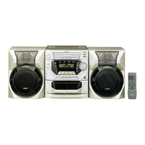
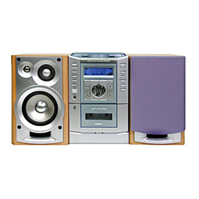
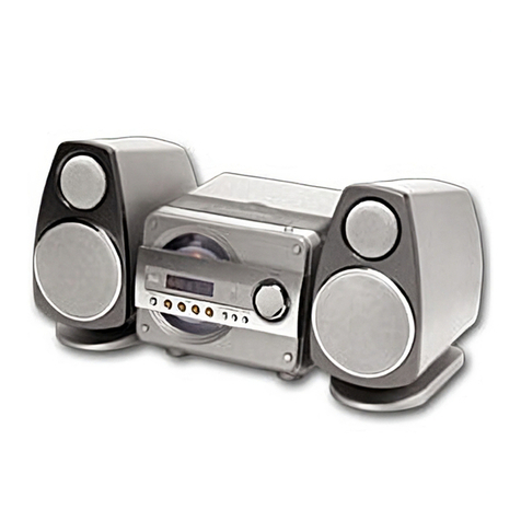
Sanyo DC-D9 User manual

....
Service Manual Mini Component
System
..
.,, .
.:,
.....
:.- CONTENTS
..
SPECIFICATIONS ................. 1
LASER BEAM SAFETY PRECAUTIONS .1
WHAT TO DO IF . . . . . . . . . . . . . . . . . . 2
REMOVAL AND INSTALLATION ...... 2
CD CHANGER OPERATION
DESCRIPTION ................... 4
CD MECHANISM ADJUSTMENTS ..... 7
CD PLAYER ADJUSTMENTS ....... 11
TAPE DECK ADJUSTMENTS ....... 13
IFILE NO. I
DC-D9 (AU)
PRODUCT CODE No.
129 472 04
TUNER ADJUSTMENTS . . . . . . . . . . . 15
EXPLODED VIEW . . . . . . . . . . . . . . . . 16
PARTS LIST ................... 17
SCHEMATIC DIAGRAM . . . . . . . . . . . . 28
WIRING DIAGRAM ............... 30
[(2 BLOCK DiAGRAM &
DESCRIPTION .................. 44
IC &TRANSISTOR VOLTAGES . . . . . . 51
........................................................................................................................................ .........:
~This service manual consists of “DC-D9U “(Main unit), “RB-D9” (Remote control )~
~and “SX-D9 “(Speaker system ).
........................................................................................................................................... .......
.. .,
REFERENCE No. SM580501

SPECIFICATIONS
TUNER SECTION
Reception frequency .FM :87.5-108.0 MHz
(50 kHz steps)
AM :522-1,611 kHz
(9kHz steps)
CASSEITE DECK SECTION
Track system ....... 4track, 2-channel stereo
Frequency response . . 80 Hz -13,500 Hz
Signal to noise ratio . . 50 dB
Wow &Flutter . . . . . . 0.15 %(WRMS)
Tape speed ........ 4.75 cmfsec
Fast forward and
rewind time .... Approx. 110 sec. (C-60)
CD PLAYER SECTION
Type .............. Changer, 3-disc -
Channels .......... 2-channel stereo
Sampling frequency . . 44.1 kHz
Pick-up ............ optical 3-beam semiconductor laser
Laser output ........ 0.6 mW (Continuous wave max.)
Wave length ........ 790 nm
Frequency response . . 20-20,000 Hz
Wow &Flutter . . . . . . Below measurable limits
LASER BEAM SAFEN PRECAUTIONS—
●Pick-up that emits alaser beam is used in this
AMPLIFIER SECTION
Output power .......
Inputs .............
outputs ...........
GENERAL
Power requirements . .
Power consumption . .
Dimensions (WXHXD) .
Weight . . . . . . . . . . . .
SPEAKER SYSTEMS
Type. .............
tJnti used . . . . . . . . . .
12.5WX2
(at 4ohms, 10% distortion )
VIDEO IN :400 mV/50k ohms
SPEAKER :4 ohms
PHONES :8-32 ohms
AC :230-240 V, 50 Hz
45 w
Approx. 270 x300 x290 mm
Approx. 5kg
2way bass reflex
Woofer: 12 cm cone type
Tweeter :piezoelectric
Maximum power-handling capacity 25 W(peak)
Nominal impedance . . 4ohms
Dimensions (WXHXD) .Approx. 180 x300 x194 mm
Weight ............ Approx. 1.6 kg (per speaker)
Specifications subject to change without notice.
CAUTION :
USE OF CONTROLS OR ADJUSTMENTS
OR PERFORMANCE OF PROCEDURES
OTHER THAN THOSE SPECIFIED
HEREIN MAY RESULT IN HAZARDOUS
RADIATION EXPOSURE
LASER OUTPUT ..... 0.6 mW Max. (CW)
WAVELENGTH . . . . . . 790 nm
Dplayer. .
\{0!
CUSS 1LASER PROOUCr
LUOKAN 1l_EERIJuIE
XLASS 1IASEPNPARAT
.....
CAUTION-INVISIBLELASERRADIATIONWHENOPENAND
lNTEfiLOCKSOEFEATED.AVOIOEXPOSURETOBEAM.
ADVARSEL-USYNLIGLAsEflsmktrw VEOlIBNiNG,NAfl
SIKKERHEDSAFBRYOEREERUDEAFFUNKTION,UNDGhUOSA3_TELSE
FORSTRALING.
VARNIN~-OSYNLIGLASERSTRALNING.NAROENNADELAROPPNAO
OCHSPARRARURKOPPLAO.STRALENARFARLIG.
VORSICHT;UNSICHTBARELASERSTRAHLUNGTRITTAUS,WENN
QECKEL~EOFFNETUNOWENNSICHERHEITSVERRIEGELUNG
UBERBRUCKTtST.NICHT,DEMSTRAHLAUSSETZEN.
VARO!Avattaessaja suojalukihrsohilettaessaoifiittiina
nakymattomaiieiasersateiiyiie.Aiakatso ateeseen. A
...
–l-

...... WHAT To DO IF
If the operation of the unit or display is not normal,
or you wish to clear the contents of the memory.
1.
2.
3.
4.
Disconnect the power cord’s plug from the
electrical outlet.
Press the RESET button for at least 20 seconds.
Connect the power cord.
Press the POWER button to turn the power on.
REMOVAL AND INSTALLATION
●
,-, ●
... . . ●
●
...”....
..:
.. .
RESET
k
/\4
Disconnect the power cord’s plug from the electrical outlet.
All wiring should be returned to the original position after work is completed.
First have ready many the new FIXERS (61 4129 2496) for replacement.
Arrange the lead wires so that they are not near the heat sink.
/-%
a. CABINET
(1) Remove the 10 rear panel mounting screws. (@)
(2) Remove the BALANCE knob. (@)
Press the STOP/EJECT Button.
Open the cassette compartment lid. (~)
b. TAPE AND CD MECHANISM BLOCK
(1) Remove the TAPE MECHANISM mounting
&
Iw
screw. (0) *
(2) Remove the 2CD MECHANISM mounting ~
screws. (0)
(3) Remove the chassis mounting screw. (@) ‘$2 :.:!””[’:> 1‘
,.
-2-

REMOVAL AND INSTALLATION
c. POWER TRANSFORMER
(1) Removal the2shield cover mounting screws.(@)
(2) Removal the ACpower socket mounting screw.(@)
(3) Remove the4power transformer mounting screws.(@) /“’”
d. CHASSIS
(1) Removal
(2) Removal
(3) Removal
(4) Removal
the 2TUNER, AMP. &CD P.W.Board mounting screws. (~)
the TUNER, AMP. &CD P.W.Board. (@,@)
the FRONT P.W.Board. (@,@,@)
the 2CD mechanism mounting screws. (~)
—-6is&
.
/’
.’
,
/J
/’
,/
-3-

c1) CHANGER OPERATION DESCRIPTION
●
●
●
a.
This set is capable of stocking and playing up to 3CDs.
While playing aCD, other discs can be replaced.
In this case, press the button for the disc No. you wish to remove, and then press the OPEN/CLOSE button.
When the “POWER” button is turned off, the power turns off after the discs are loaded in the disc trays.
MOTOR &MECHANISM SWITCHES LAYOUT
,..
OPEN
.,
rLOAD /UNLOAD MOTOR
~LOAD SWITCH (SW3)
I \I -------
(JNLOAD SWITCH (SW5 )
-d 6F
-PI AY SWITCH (5k’d4 )
CLOSE SWITCH (SW2) ?.
/&
OPEN SWITCH (SW1 )1A/
DISC 1.-1’
DISC 2-g
IXsc 3
%t-wNMOTO
CLOSE END SWITCH
/OPEN/CLOSE RACK GEAR
!2d--
-s+ OPEN/ CLOSE MOTOR
-; .“
CWEN END SWITCH
-4-

CD CHANGER OPERATION DESCRIPTION ,.,.
b. UP/DOWN FUNCTION (DURING “UP” )
(1) The rotation of the UP/DOWN MOTOR (624) rotates the UP/DOWN DRIVE GEAR (605) in the counter-clockwise direction.
(2) In connection ~jth this, the TRAY HOLDER SLIDE (640) moves forward, and at the same time, the RIGHT SLIDE (575) is
moved backwards by the SYNCRO LEVER (632).
UP/DOWN CAM GER 1(602)
UPIDOWN ORIVE GEAR 1/UPI DOWN IDLER 2(609)
UPIDOWN
DRIVE (
(605) UPIDOWN
MOTOR (624)
/~-l--rJ- UPI DOWN IOLER 1(607)
UPI 0dWy64;;VE GEAR 2\U;IDOWN IDLER 2(609)
UP/DOWN CAM GEAR 2’ (603)
+“ -1
--.,\w
SYNCRO LEVEfi (;32) // A‘“l
/
-.. -./
32 ’79==4P
<: UPI DOWN
DRIVE GEAR 2
(603)
/
-5-
. ..

;:CD CHANGER OPERATION DESCRIPTION
c. LOAD/UNLOAD FUNCTION
(1) The rotation of the LOADA-JNLOAD MOTOR rotates the LOADWNLOAD DRIVE GEAR (552) in the clockwise direction.
(2) The DRIVE GEAR and the gear portion of the TRAY mesh together and the TRAY moves backwards.
(3) The completion of TRAY movement causes the UP/DOWN MOTOR to operate and lower the TRAY HOLDER, putting the
unit to chucking stayus.
LOADIUNLOAD DRIVE GEAR
A-
(552)
-’-.1
---
Disc
\ . .- m“:’”
...
.....
....
A
%!=flL J’++ “~~;:’”’//::’’-’’’”
-.
.--~-. \
-\\. ..
d. OPEN/CLOSE MECHANISM \-i .fi
(1)The rotation of the OPEN/CLOSE MOTOR
OPEN/CLOSE IDLER GEAR via the BELT and PULLEY,
and the RACK GEAR whitch is intermeshed with the
OPEN/CLOSE IDLER GEAR moves forward during “OPEN”,
backwards during “CLOSE”. CLOSE END SwlTCH (SW 2)
OPEN /CLOSE RACK GEAR
OPEN/CLOSE LEVER OPEN/CLOSE lDLER GEAR
OPEN/CLOSE IDLER PULLEY TRAY GUIDE TRAY
:-,-,:%-3---- --
OPENICLOSE MOTOR
OPEN END SWITCH (SW1)
-6-

CD
a.
MECHANISM ADJUSTMENTS ..
CD CHANGER Mechanism AND OPEN/CLOSE MOTOR
/5?3 .........................................................................
~Note :
//Ah.7. h
~EM-50L ............. MOLYKOTE, EM-50L :
:SG-7 ............... SANGREA=,SG-7;
:G-474B .............. FLOILOIL, G-474B i
....
.......... ...................................
b. UP/DOWN GEAR
‘m
‘a.,
.......... . ....
mc. CD MECHANISM BLOCK
\
‘,
,.

CD MECHANISM ADJUSTMENTS
d. LOAD/U NLOAD MOTOR $?
d‘“r
\LOAD/U NLOAD CAM GEAR
OR
2
1
., ,..
e. TRAY HOLDER f. CD MECHANISM BLOCK
.
B-TOP ENCOURAGE
CHUCK BRACKET
i+
,.

CD MECHANISM ADJUSTMENTS ,...
. .
g. REPLACEMENT AND LUBRICATION OF THE CD MECHANISM
........... ... ......................................................
~Note:
:EM-50L ............. MOLYKOTE, EM-50L!
:SG-7 ............... SANGREASE,SG-7 !
:G-474B .............. FLOILOILG-474B :
........................................................................ LUG
‘\ ~, \;
1’/ \ \\\
\ \\\ LUG
\\\
/’/’ c1 -x\\\ \
II x’:.
// ,,.-
. .
1/ -.
/’: ~q
1,
,
TUNER, AMP &CD P.W.B
;; CHASSIS
,=== (~<~OLE
.==.
h. CD BASE MECHANISM
*PLUS MARK +PL”US t.lARK
1..
I
I
I
a
‘SP1NOLE(5L:D MOTOR PW.L3
\\+ ....’
.. . e
-9- \- -“”
...-
...
...

. .... .. ... . ... . . ... . . . . . ... .
. ... .
.“. ...
. . .
.- ...
,. ..-
.:.
CD MECHANISM ADJUSTMENTS
i. CD MECHANISM
(a) Replacement of the spindle motor BOND &
●First, prepare thenewturntable (701-l )and new special
?!3
WASHER --IT ABOUT
washer (701-4,701-5 )for replacement.
The removed turntable will be deformed by the heat of
,8mm ‘B;i;+rBoND-fl
the soldering iron, and cannot be reused. ox
●Prepare dial-type calipers.
(1)
(2)
(3)
(4)
(5)
(6)
(7)
(8)
The attached bonding material can be dissolved by using
a60W soldering iron to heat the shaft at the upper part
of the turntable for about one minute.
The turntable can then be removed from the shaft by very fy
carefully applying force upward at the center of the lower surface @701-1
of the turntable.
Remove the two screws (701-2 )and remove the spindle motor
(701-6).
Attach the special washer (701-4, 701-5 )to the spindle mot
Clean the spindle motor’s shaft.
To clean them, use asoft cloth soaked in isopropyl alcohol.
Apply asmall amount of amixture of the “Three Bond 2001
and “201 5F” bonding materials to the motor’s shaft.
Install the turntable as shown in the figure.
Secure the turntable by pressing gently.
Be sure to wipe away (by using apiece of cloth, or similar
material) any bonding material coming out of the hole.
(b) Replacing the pick-up
(1)
(2)
(3)
(4)
(5)
Insert the pick-up rail (703 )into the base chassis. (701-3 )
If the lath of the base chassis (701-3) are missing when
the pick-up rails have been installed, first wipe the
tips of the rail with alcohol.
After the pick-up has been replaced, apply grease
(FLOIL G-474B) to the m] sections.
The pick-up P.W. Board pattern is “shorted”, as shown
in the figure, so that the new pick-up will not be
susceptible to the effects of static.
Set the pattern to “open” after the pick-up has been re~’-
,..
II~’”’-z
I
1
a.
SLED Mt3TOR “ “ -&%”
/--’0 ‘<-7’0
C722) I~%
8
(BE SURE AT THIS TIME,
NOT TO TOUCH ANY OTHER PART.)

CD PLAYER ADJUSTMENTS ,.
a. PREPARATIONS
(a) Measuring instruments, tools and filter
(1)
(2)
(3)
Test disc. :YEDS 18 (SONY) or etc.
Oscilloscope :SS5711 (1OMHz or dual-phenomenon)
or Memory scope :DSS6521 (Storagescope)
Screwdrivers (non-metallic) for adjustments
b. PARTS LOCATION
TRACKING BALANCE EYE PATTERN
+(+) (+)
OSCILLOSCOPE _OSCILLOSCOPE
(-) (-) .
<–!
(3[.CN102
•~
VR101 TP1 (RF)
TRACKING TP2(FE)
BALANCE TP3(TE)
TP4(VC)
?TEST POINT
c. ADJUSTMENTS
Adjustment Measuring Input output Adjustment
Item Adjustment value
instrument connection connection location
(a) Tracking Oscilloscope —TP3:TE’ VRIO1 Waveform symmetry
balance TP4:VC A=B
(b) Checking Check be sure that the “eye”
the “eye” Oscilloscope —TP1:RF —pattern is at the center of the
TP4:VC
pattern waveform and that the diamond
shape is clearly defined

.-, CD
(a)
(1)
. ...’ (2)
(3)
(4)
(5)
(6)
PLAYER ADJUSTMENTS
Tracking balance adjustment
Within one second after pressing emok
&REPEAT switches at the same time, press
the MEMORY switch. (@,@)
(Service mode: TRACKING BALANCE)
I-—1
[-l-l- !I._ ----
Connect an oscilloscope to
Set the test disc. (DISC 1)
TP3 (TE) and TP4 (VC).
PLAY /PAUSE switch push “ON”. m~l
Adjust VR101 so that the oscilloscope’s waveform is RF
symmetrical, as shown in the illustration.
To cancel service mode, disconnect the power cord’s plug
from the electrical outlet.
TE
“: (b) Checking the “eye” pattern
(1) Switch “ON” the POWER.
(2) Connect an oscilloscope to TP1 (RF) and TP4 (VC).
(3) Load the test disc.
(4) PLAY switch push ON.
(5) Check to be sure that the “eye “pattern is at the center of
waveform and that the diamond shape is clearly defined.
(6) Press the STOP button.
(7) Switch “OFF” the POWER.
-12-
Ov
(%4
Osc’L
I

TAPE DECK ADJUSTMENTS
Measuring Adjust Adjust
Adjustment Item Test Tape Output connection Note
Instrument location value
(a) HEAD AZIMUTH VTT738 etc. AC-voltmeter SPEAKER TERMINAL HEAD AZIMUTH
TAPE “8” Max.
(l OkHz) SCREW ---
(b) HEAD AZIMUTH VTT738 etc. AC-voltmeter SPEAKER TERMINAL HEAD AZIMUTH
TAPE “A” Max. ---
(lOkHz) SCREW
(c) MOTOR SPEED MTT-111 FREQUENCY
(NORMAL) (3,000 Hz) COUNTER SPEAKER TERMINAL SVRO1 3,000 Hz ..-
a.
(a)
(1)
(2)
(3)
(4)
(b)
HEAD REPLACEMENT AND AZIMUTH ADJUSTMENT
Head replacement
After replacement, demagnetize
the heads by using adegausser.
Be sure to clean the heads
before attempting to make any
adjustments.
Be sure both channels (1 and 2)
are the same level
(Using adual-channel oscilloscope).
All wiring should be returned to
the original position after work
is completed.
.
Head azimuth
●TAPE “A”
TAPE “B”
-E. HEAD RIP TAPE “A”
HEAD PLAY HEAD
(1) Load a test tape (VTT-738, etc.: 10 kHz) for azimuth
adjustment.
(2) Press the PLAY button.
(3) Use aflat-tip ( - ) screwdriver to turn the screw for
azimuth adjustment so that the left and right outputs
are maximized at the same phase during playback.
(4) Press the STOP button.
●TAPE “B”
(1)
(2)
(3)
(4)
..
Load a test tape for azimuth adjustment.
Press the PLAY button.
Azimuth screw adjustment.
Press the STOP button.
●After making the adjustment, secure the azimuth
adjustment screw by applying screw lock (TB- 1401 B).
-13-
.
.:.-

. . .. . ....-. .’,
...... TAPE DECK ADJUSTMENTS
b. MOTOR REPLACEMENT AND SPEED ADJUSTMENT
(a) Motor replacement
(l) See illustration at right.
<-..
..’:.
(b) Motor speed
(1) Insert the test tape (MTT-1 11,
(2) Press PLAY button.
....
. ,,..
(3) Adjust SVRO1 so that the frequency counter shows a
rea~ng of 3,000 Hz.
(4) Press STOP button.
SVRO1
H
c. CHECKING THE MECHANISM TORQUES
●Clean the head, capstan and pinch roller before making any measurement.
TAPE “A &B“
Measurement Take-up torque Back tension Tape tension
Cassette for PLAY: TW-21 11A Drive-power cassette
PLAY: TW-21 11A
measurement F.FwD/REw:TW-2231 TW-2412
PLAY 30-60 gr.cm 2.0- 5.0 gr.cm 60gr or more
F.FWD /REW 55-120 gr.cm
-14-

“,. :,... .. ”-. “.” . . . “.. .- i
TUNER ADJUSTMENTS ,.
,...
.LJSe aplastic screw driver for adjustments. ●Speaker impedance :4 ohm
.Standard Output :500 mW .FM MODE switch :STEREO
.TUNING FM :87.5-108.0 MHz (50 kHz step )
AM :522-1,611 kHz (9kHz step )
FM ANTENNA
75 ohm
!I
QI
AM LOOP
ANTENNA 1“
L2101
=3
L2151
Ho
40
CT251
flL2102
TP2.41 (VT )
4nJ2437
TP242 (G)
++2239
TP231(L)
\TP232(R)
‘2317 g#’&2318
TP2{!&’9
SG RF Level :75 ohm Open Voltage dBPV
Antenna :75 ohm unbalanced ,Modulation :1 kHz,
a. ADJUSTMENTS OF FM BAND Dev. :~75 kHz (MONO) f40 kHz (STEREO) k6.75 kHz (PILOT)
Adjusting Connections Position of ‘VTVM
Step Circuit SG Frequency Adjustment Oscilloscope or
Input output tuning dial DC voltmeter
Connect to Digital
Tuning 87.5 MHz Low end L2102
10.90 -I.30V
--- DC voltmeter
coverage TP 241 (H), TP 242 (G) 108.0 MHz High end -- less than 9.OV
Connect to VTVM ..-. ,
TP231 (H) or TP232 (H), 90.0 MHz 90.0 MHz L2101
2Tracking FM Antenna Max.
(SG =8dB#) TP233 (G)
106.0 MHz 106.0 MHz ---
SG Modulation :1,000 Hz, 30°7&
b. ADJUSTMENTS OF AM BAND IRE LOOPAntenna
Adjusting
Step Circuit
--1--
Tuning
1coverage
Connections Position of VTVM
SG Frequency Adjustment Oscilloscope or
Input output tuning dial DC voltmeter
I1
IConnect to Digital I522 kHZ ILow end ]L2152 I1.00t0.05V I
..-
Connect AM SG to
Test Loop
(SG =80dB4V)
DC voltmeter
TP241 (H), TP242 (G) 1611 kHz High end -- less than 8.OV
Connect to VTVM 603 kHz 603 kHz L2151
TP231 (H) or TP232 (H), Max.
TP233 (G) 1404 kHz 1404 kHz CT251

~-EXPLODED VIEW (CABINET &CHASSIS )
“.
Vol
-7- .,
,..
,:,
...
.-
.“
Y20
.A

. . .
PARTS LIST
PRODUCT SAFETY NOTICE
Each precaution in this manual should be followed during servicing. Components identified with the IEC symbol ~in the parts list
and the schematic diagram designate components in which safety can be of special significance. When replacing acomponent
identified ~, use only the replacement parts designated, or parts with the same ratings of resistance, wattage or voltage that are
designated in the parts list in this manual. Leakage-current or resistance measurements must be made to determine that exposed
parts are acceptably insulated from the supply circuit before returning the product to the customer.
CAUTION :Re@ar type resistors and capacitors are not listed. To know those values, refer to the schematic diagram.
Regular type resistors are less than l/4W carbon type resistors.
Regular type capacitors are less than 50V and less than 1000PF type of Ceramic type and Electrical type.
N.S.P :No~ available as”service pans.
‘ACKING &ACCESSORIES
Ref. No. Past No.
614 270 8095
614 267 8503
614 267 8497
64S 012 1302
614 270 8125
645 005 1227
614 245 0055
~614 256 5292
645 009 0271
64!5 005 7007
I
:ABINE
Ref. No
1
2
3
4
5
6
7
8
9
10
11
12
13
14
15
16
17
18
19
22
23
24
25
26
27
28
29
41
42
43
44
45
46
47
49
&Ct-mssls
P- No.
614 270 7609
614 270 7623
614 267 7001
614 267 7018
614 267 7780
614% 270 8316
614i 267 8312
614, 267 7674
614 267 7773
614 270 7531
614 267 6769
614 267 6738
614 267 6745
614 267 6776
614 267 6783
614 267 6790
61$ 267 6806
614 267 6813
614 267 6820
614 270 8422
614 267 8237
614 267 8244
614 267 8251
614 267 8268
614 267 8305
614 i273 9167
614 261 1319
614 267 6752
614 267 6721
614 267 6905
614 Z70 8408
614! 2?16 9346
614 130 0382
614 2?77 2256
614 270 7586
INSTRUCTION MANUAL
ASSY,ANTENA,LOOP,AM
ANTENNA,FM,LEAD
POWER CORD,AC
REMOCON,RB-D9,REMOTE
BATTERY COVER,REMOTE CONTROL
CONTROL1
Descricstion
ASSY,COVER,LEFT,TAPE B
ASSY,COVER,RIGHT,TAPE A
LID,CASSETTE,LEFT,TAPE B
LID,CASSETTE,RIGHT,TAPE A
SPRING,WIRE,CASSETTE OPEN
ASSY,GEAR,CASSETTE
MOUNTING,GEAR SUPPORT
ASSY,DOOR,CD
SPRING,TENSION,CD DOOR CLOSI
ASSY,CABINET,FRONT
BUTTON,VOLUME
BUTTON,FUNCTION
BUTTON,CO PLAY
BUTTON, RECORD,TAPE”B”
BUTTON,PLAY,TAPE”B”
BUTTON,REW,TAPE”B”
BUTTON, F.FWD,TAPE”B”
BUTTON,STOP/EJECT,TAPE”B”
BUTTON,PAUSE,TAPE”B”
MOUNTING,MECHANISM BUTTON
BUTTON,PLAY,TAPE”A”
BUTTON, REW,TAPE”A”
BUTTON, F.FWO,TAPE”A”
BUTTON,STOP/EJECT,TAPE”A”
KNOB, ROTARY,BALANCE
BUTTON,DUBBING/BEAT CANCEL
MOUNTING,POWER AMP.PWB
BUTTON,TUNING/
BAND/MODE/PRESET
BUTTON,POWER
CHASSIS,CD MECHANISM PWB
HOLDER,TAPE DECK PWB
SPRING,PLATE,RECORD/PLAY
LUG,GROUNO
SHIELD,COVER,POWER
TRANSFORMER
ASSY,CABINET,BACK
Ref. No. Part No.
614 267 7032
614 208 0986
614 129 4971
614 224 3688
614 231 6832
Description
SHIELD,CABINET BACK MTG,
CUSHION,1OX4OMM,
MECHANISM LEAD MTG.
FIXER,NYLON,LEAD MTG,
LABEL,SAFETY,LASER CAUTION
LABEL,SAFETY,LASER,CLASS 1
‘IXING I
Ref. No.
Yol
Y02
Y03
Y04
Y05 .’
Y07 -
Y08
Y09
Ylo
Yll
Y12
Y13
Y14
Y15
Y16
Y17
Y18
Y19
Y20
Y21
Y22
-17-
4RTS
Part No.
411 021 4906
411 021 3701
411 021 3701
411 021 3701
411 021 3503
411 020 8905
411 021 3503
411 021 3503
411 021 3503
411 021 3503
411 020 8905
411 028 2905
411 028 2806
411 021 3503
411 028 9201
411 021 3503
411 021 3503
411 021 3503
411 021 3503
412 003 1708
411 021 3503
Description
SCR S-TPG BIN 3X20MM,
CABINET REAR
SCR S-TPG BIN 3X1OMM,
CD MECHANISM
SCR S-TPG BIN 3X1OMM,
VIDEO SOCKET
SCR S-TPG BIN 3X1OMM,
AC POWER SOCKET
SCR S-TPG BIN 3X1OMM,
SHIELD,POWER TRANSFORMER
SCR S-TPG 8RZ+FLG 3X1OMM,
POWER TRANSFORMER
SCR S-TPG BIN 3X1OMM,
FRONT P.W.BOARD
SCR S-TPG BIN 3XIOMM,CHASSIS
SCR S-TPG BIN 3X1OMM,CHASSIS
SCR S-TPG BIN 3X1OMM,
TUNER,AMP. & CD P.W.BOARD
SCR S-TPG BRZ+FLG 3X1OMM,
TAPE MECHANISM
SCR S-TPG PAN 2X4MM,
TAPE MECHANISM BRACKET
SCR S-TPG PAN 2X3MM,
RECORD/PLAY SPRING PLATE
SCR S-TPG BIN 3X1OMM,
TAPE DECK PWB
SCR S-TPG PAN 3X4MM,GND,
CD MECHANISM
SCR S-TPG BIN 3X1OMM,
FUNCTION BUTTON
SCR S-TPG BIN 3X1OMM,
CD PLAY BUTTON
SCR S-TPG BIN 3X1OMM,
VOLUME BUTTON
SCR S-TPG BIN 3X1OMM,
MECHANISM BUTTON BRACKET-M
SPECIAL SCREW,FRONT PANEL
SCR S-TPG 81N 3X1OMM,
POWER AMP. PWB
9
..”.”

,.-. . . i
PARTS LIST
:LECTRII
Ref. No.
61
62
63
CN121
CN31O
:;311
;;312
:;313
or
“UNER,
Ref. No.
71
BPF21
C1153
C2154
C2463
C4903
CF221
CF222
CF231
CF232
CN101
CN102
CN103
CN104
CNI05
CN131
CN201
CN401
CN402
CN403
CN404
CN405
CN414
CN420
CN424
CN432
CN434
CT251
D1351
;:361
or
D1371
or
D1372
or
D1601-4
D2101
D2102
D2103-5
or
or
or
4L PARTS
Part No.
/h645 011 1622
d1423 016 9605
614 272 3135
614 271 2191
614 253 8463
614 273 0393
614 251 1404
614 273 0386
614 251 1411
614 273 0416
614 251 3279
614 273 0409
614 265 9458
MP.&CD P.W.I
Part No.
614 272 3036
614 256 7852
614 125 6443
614 252 1045
403 058 5209
403 082 0201
403 106 1603
403 135 0400
614 030 5074
614 030 5074
614 248 4432
645 009 5856
645 010 1465
645 005 8110
645 005 8127
614 271 2184
614 221 8273
614 273 3905
645 005 0695
.645 006 1141
645 006 1875
645 006 1875
614 224 9864
645 006 0885
645 004 2881
614 020 1222
614 020 1246
614 270 6411
614 268 3866
614 007 6356
407 099 5402
407 051 7208
407 099 4504
407 051 5808
407 099 4504
407 051 5808
407 007 9904
407 012 4406
407 004 9709
407 157 8109
407 157 8109
407 007 9904
407 012 4406
407 012 5809
407 153 6109
I407 007 9904
Description
TRANSFORMER,POWER,PT401
FUSE 250V 0.4A,FU491
PWB,APPEARANCE
ASSY,CONNECTOR-S,4P,
CO-CD MECHANISM
ASSY,CONNECTOR-S,4P,R/P HEAI
ASSY,CONNECTOR-S,4P,R/P HEAl
ASSY,CONNECTOR-S,3P,P HEAD
ASSY,CONNECTOR-S,2P,E HEAD
ASSY,CONNECTOR-S,6P,
MECHANISM SWITCH
ASSY,CONNECTOR-S,6P,
MECHANISM SWITCH
SPACER,POWER TRANSFORMER-PWI
3ARD ASSY
Description
ASSY,PWB,TUNER,AMP & CD
SHIELD,PWB MTG.
CUSHION, 15X25X3MM,SHIELD-PWI
FILTER,LC,FM
POLYESTER 0.15U
POLYPRO 470P
NP-ELECT lU
ELECT 3300U
I.F FILTER,FM,REO
I.F FILTER,FM,REO
FILTER,At4
K50V
J100V
Q50V
M25V
DISCRIMINATOR,CERAMIC,FM
SOCKET,FPC 13P
PLUG,4P
PLUG,6P
ASSY,WIRE,8P
TERMINAL,lP
CORD,lP CONNECTOR
TERMINAL,4P,ANTENNA
JACK,PHONE D6.43
PLUG,2P
PLUG,2P
SOCKET,3P
PLUG,13P
PLUG,2P
PLUG,3P
SOCKET,5P
ASSY,WIRE,5P
ASSY,WIRE,3P
TRIMMER,llPF
ZENER DIODE MTZJ6,2B
ZENER DIODE GZS6.2Y
ZENER DIODE MTZJ3.9A
ZENER DIODE GZS3.9X
ZENER DIODE MTZJ3.9A
ZENER DIOOE GZS3”.9X
DIODE GMAO1
DIODE 1SS133
DIODE DSK1OC
OIODE SVC211-B
DIODE SVC211-B
DIODE GMAO1
DIODE 1SS133
DIODE 1SS176
DIODE 1SS119-041
OIOOE GMAO1
Ref. No.
or
or
or
D2151-2
D2452
or
or
or
D4901
D4902
or
D4903
HSOO1
IC101
IC102
IC104
IC106
or
IC131
IC132
IC211
IC231
IC245
IC402
IC403
XC404
or
or
IC405
Or
L1401
L1500
L1501
L2101
L2102
L2103
L2104
L2151
L2152
L2451
LGOO1
LGO02
PR491
QI101-2
or
or
or
or
;;201
;:202
Q1211
Or
;;321
or
Or
or
or
or
Q1351
or
or
–l8-
Part No.
407 012 4406
407 012 5809
407 153 6109
407 091 5004
407 007 9904
407 012 4406
407 012 5809
407 153 6109
407 099 6706
407 007 9904
407 012 4406
407 127 3905
614 249 0754
409 327 3402
409 317 8509
409 322 2707
409 039 7408
409 018 4305
~409 127 1400
409 114 4803
409 049 2103
409 345 5204
409 066 7600
409 265 3601
409 211 6601
~409 026 8500
h409 057 6407
h409 169 7804
409 051 2801
409 336 0508
645 002 1534
614 212 3171
614 212 3171
614 034 5988
614 034 7197
645 002 1534
645 002 1534
614 240 0913
614 240 0852
645 001 4581
614 051 9785
614 217 7266
/h645 006 2322
.405 004 4601
405 003 5401
405 006 1905
405 006 1806
405 002 1305
405 002 1107
405 009 5207
405 001 9302
405 008 6809
405 000 3103
405 078 2909
405 001 0200
405 019 3705
405 017 9709
405 011 8609
405 011 8500
405 014 5209
405 014 5407
405 000 0508
405 078 2305
405 001 1108
Description
OIODE 1SS133
DIODE 1SS176
OIODE 1SS119-041
VARACTOR t310DE SVC321SPA-C-2
DIODE GMAO1
DIODE 1SS133
DIODE 1SS176
DIODE 1SS119-041
ZENER DIOOE MTZJ13A
DIODE GMAOl
DIODE 1SS133
DIODE MTZJ5.6B
HEAT SINK,IC401 MTG.
IC CXA1782BQ
IC BA6398FP
IC CXD2518Q
IC NJM4558D
IC LA64580
IC LB1648
IC LB1641
IC TA7358P
IC TA2057N
IC LM7001
IC TC9213P
IC NJM4558L
IC L78M05
IC UPC7BW15H
Ic NJM7BU05FA
IC TC40523P
IC BU4052BC
INDUCTOR,8.2U K
INDUCTOR,FERITE
INOUCTOR,FERITE
VHF COIL
VHF COIL
INDUCTOR,8.2U K
INDUCTOR,8.2U K
TRANSFORMER,RF
TRANSFORMER,OSC
INDUCTOR,1OOU K
(L2451,L4901,L4902)
LUG,GND
LUG,LEAII AfTG,
PROTECTOR,IC,O.4A 50V
TR 2SA608-F-SPA
TR 2SA1317-U
TR 2SA933S-S
TR 2SA933S-R
TR 2SA1048-Y
TR 2SA1048-GR
TR 2SB927-S
TR 2SA102O-Y
TR 2SB808-F-SPA
TR OTC114ES
TR BA1A4M
TR RN1Z02
TR 2SC536-G-AUD-SPA
TR 2SC3330-U
TR 2SC1740S-S
TR 2SC1740S-R
TR 2SC2458-GR
TR 2SC2458-Y
TR DTA114ES
(Q1351.Q1361,Q1371)
TR Bt41A4hf
TR RN2202

,,,
.. ...
. ....
PARTS L
Ref. No.
Q2101
Q2201
Q2302
;;451
;;461
Q2462
Q2901
Q4721
or
or
or
or
:;901
or
or
;;902
or
or
or
or
:;903
or
;;921
o,r
;;922
or
or
R1350
R1371
R4901
S4901
or
S4950
S4951
SAOO1
VR101
VR405
X1401
or
X2301
X2451
or
or
XF401
DOWER
Ref. No.
72
C4704
C4804
C4913
CN41O
CN411
CN412
D4011
D4012
Part No.
405 016 0806
405 016 0806
405 000 6104
405 018 2501
405 000 0904
405 036 3702
405 019 3705
405 019 3705
405 019 3705
405 019 3705
405 017 9709
405 011 8609
405 011 8500
405 014 5209
405 014 5407
A405 035 7107
~405 035 7206
&405 095 1602
A405 095 1701
405 019 3903
405 017 9709
405 011 8609
405 011 8500
405 014 5209
405 014 5407
405 000 3103
405 078 2909
405 001 0200
405 000 1208
405 078 2206
405 001 1207
405 000 3103
405 078 2909
405 001 0200
~402 045 0302
402 049 2500
~402 060 5306
614 247 6840
614 023 9683
614 221 8327
614 221 8327
411 021 6405
645 001 9326
614 248 1752
614 254 6932
614 259 2137
645 009 5832
614 229 2457
614 204 0317
614 240 1118
645 006 3596
Description
TR 2SC2839-E
rR 2SC2839-E
TR DTC144ES
TR 2SC3399
TR DTA114YS
TR 2SA1564
TR 2SC536-G-AUD-SPA
TR 2SC536-G-AUD-SPA
TR 2SC536-G-AUD-SPA
TR 2SC536-G-AUD-SPA
(Q4721,Q4821)
TR 2SC3330-U
TR 2SC1740S-S
TR 2SC1740S-R
TR 2SC245?3-GR
TR 2SC24%3-Y
TR 2SD1913-fl
TR 2SD1913-S
TR 2SD2Q61-E
TR 2SD2061-F
TR 2SC536-G-AUD-SPA
TR 2SC3330-U
TR 2SC1740S-S
TR 2SC1740S-R
TR 2SC2458-GR
TR 2SC2458-Y
TR DTCI14ES (Q4903,Q4906)
TR BA1A4M
TR RN1202
TR DTA124ES
TR BN1F4M
TR RN2203
TR DTC114ES
TR BA1A4M
TR RN1202
RESISTOR 4.7 J- lW
RESISTOR 18 J- 2W
RESISTOR 1J- l/2W
SWITCH,DUBBING/BEAT CANCEL
SWITCH,TACT,FUNCTION
SWITCH,TACT,RESET
SCR S-TPG BIN 3X8MM,Q4901
VR,SEMI,1OOK N
VR,~OTARY,BALANCE
RESONATOR,CERAMIC,33.8688MH;
RESONATOR,CERAMIC ,33.86MHz
OSC,CERAMIC 456KHZ
CRYSTAL,7.2MHZ
CRYSTAL,7.2MHZ
RESONATOR,7.2MHZ
INDUCTOR,l. lUH (XF401-XF405
MP. P.W.BOARD ASSY
Part No. Description
614 275 34461 ASSY,PWB,POWER AMP.
403 059 9008
403 059 9008
403 135 9106
645 004 2898
645 005 9292
645 004 2881
~407 141 2809
~407 141 2809
POLYESTER 0.22U M50V
ELECT 3300U M35V
PLUG,3P
PLUG,5P
PLUG,2P
OIODE IN5402
OIODE IN5402
Ref. No.
D4013
D4014
HS401
IC401
Q4701
or
;;904
Q4905
or
or
or
or
or
R4705
R4805
Part No.
A407 141 2809
~407 141 2809
614 261 1234
409 274 2800
405 021 0600
405 033 6805
405 021 0204
405 018 0200
405 019 3705
405 017 9709
405 011 8609
405 011 8500
405 014 5209
405 014 5407
/h402 004 5201
~402 004 5201
411 021 3503
411 021 3503
‘OWER SUPPLY P.W.BOi
Ref. No. Part No.
13 614 272 3050
CN421 614 020 1215
CN423 ~614 239 4724
CN425 614 020 1215
CN431 614 267 8701
CN438 614 271 2870
D4001-4 ~407 088 6403
FCLP1 645 006 4760
FCLP2 645 006 4760
L4901 /h614 213 5761
or /h614 229 0408
PR490 ~614 263 8781
‘APE D
Ref. No.
74
C3911
C3917
CN301
CN302
CN304
CN305
CN306
or
CN307
03901-2
or
D3905-i
or
D3908
IC301
L3901
Q3702
or
;;703
or
or
or
or
or
-19-
:K P.W.BOARD
Part No.
614 270 6053
403 059 5000
403 061 9607
645 005 7373
645 005 8110
614 272 3098
645 005 6127
614 020 6562
614 223 9223
645 005 7366
407 007 9904
407 012 4406
407 007 9904
407 012 4406
407 099 6805
409 251 1000
645 010 7177
405 000 3103
405 078 2909
405 001 0200
405 019 3705
405 017 9709
405 011 8609
405 011 8500
405 014 5209
405 014 5407
Description
DIODE IN5402
DIODE IN5402
HEAT SINK,IC401 MTG.
IC LA4450
TR 2SD1012-G-SPA
(Q4701,Q4801)
TR 2SD1468S-S
TR 2SDI012-F-SPA
TR 2SC3331-U
TR 2SC536-G-AUD-SPA
TR 2SC3330-U
TR 2SC1740S-S
TR 2SC1740S-R
TR 2SC2458-GR
TR 2SC2458-Y
FUSIBLE RES 2.2 J- l/4W
FUSIBLE RES 2,2 J- l/4W
SCR S-TPG BIN 3X1OMM,
IC401 MTG.
SCR S-TPG BIN 3X1OMM,
HEAT SINK MTG.
RD ASSY
Description
ASSY,PWB,POWER SUPPLY
SOCKET,2P
PLUG,AC POWER SOCKET
SOCKET,2P
ASSY,WIRE,2P
ASSY,WIRE,2P
DIODE GP15D-L
HOLDER,FUSE
HOLDER,FUSE
INDUCTOR,FERITE
INDUCTOR,FERITE
IC PROTECTOR ICP-N70
6SY
Description
ASSY,PWB,TAPE DECK
POLYESTER 0.022U J50V
POLESTER 0.047U J50V
PLUG,3P
PLUG ,4P
ASSY,WIRE,13P
PLUG,6P
SOCKET,4P
SOCKET*4P
PLUG,ZP
DIODE GMAOI
OIODE 1SS133
DIOOE GMAO1
DIODE 1SS133
DIODE MTZJ13B
IC TA8189N
TRANSFORMER,OSC ,85KHZ
TR 0TC114ES
TR BRIA4M
TR RN1202
TR 2SC536-G-AUD-SPA
TR 2SC3330-U
TR 2SC1740S-S
TR 2SC1740S-R
TR 2SC2458-GR
TR 2SC2458-Y
I
Other manuals for DC-D9
4
Table of contents
Other Sanyo Stereo System manuals

Sanyo
Sanyo DC-BM300 User manual

Sanyo
Sanyo DC-DA1000 User manual

Sanyo
Sanyo DC-007C User manual

Sanyo
Sanyo DC-DAB03 User manual

Sanyo
Sanyo DC-S800 User manual

Sanyo
Sanyo DC-MX42i User manual

Sanyo
Sanyo MDG-007 User manual

Sanyo
Sanyo GCD 1500 User manual

Sanyo
Sanyo DC-DA370 User manual

Sanyo
Sanyo DC-UB1470 User manual

Sanyo
Sanyo DC-007C User manual

Sanyo
Sanyo DC-AX20 User manual

Sanyo
Sanyo G-2915NK User manual

Sanyo
Sanyo DC-BM300 User manual

Sanyo
Sanyo DC-D5 User manual

Sanyo
Sanyo GXT 4615K User manual

Sanyo
Sanyo MDG-X5 User manual

Sanyo
Sanyo DC-MCR80M User manual

Sanyo
Sanyo DC-DA180 User manual

Sanyo
Sanyo DTA-200 User manual