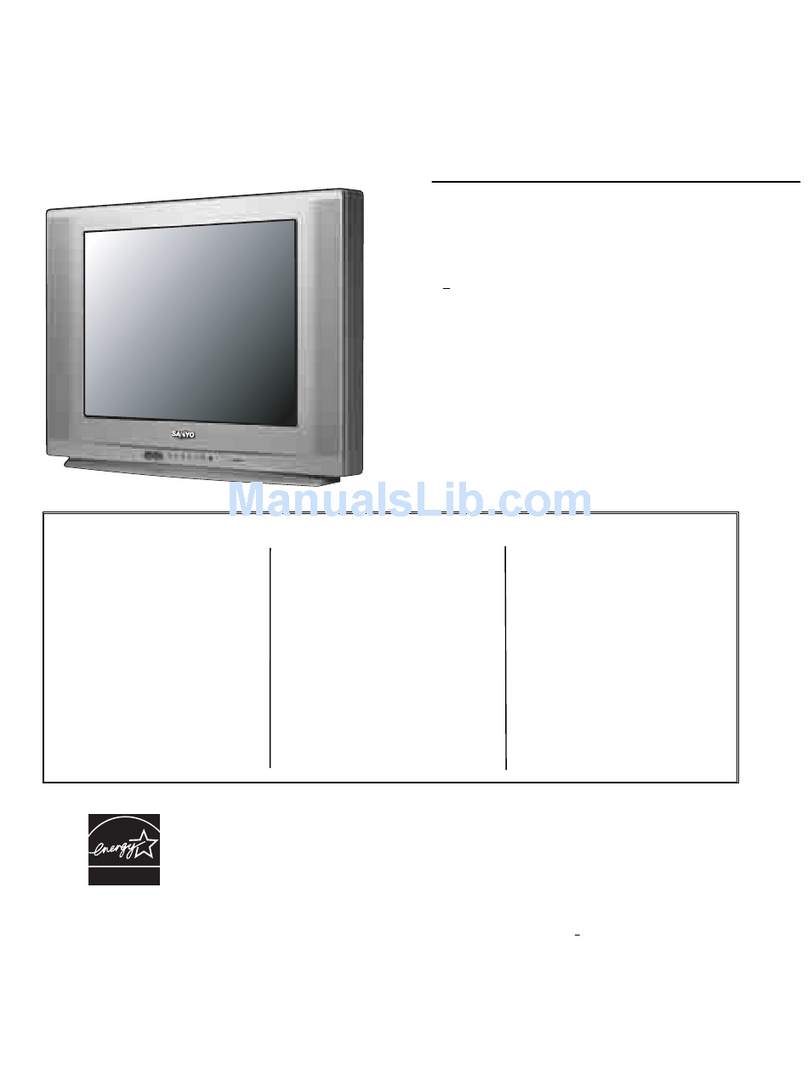
Sanyo C29FS51 User manual

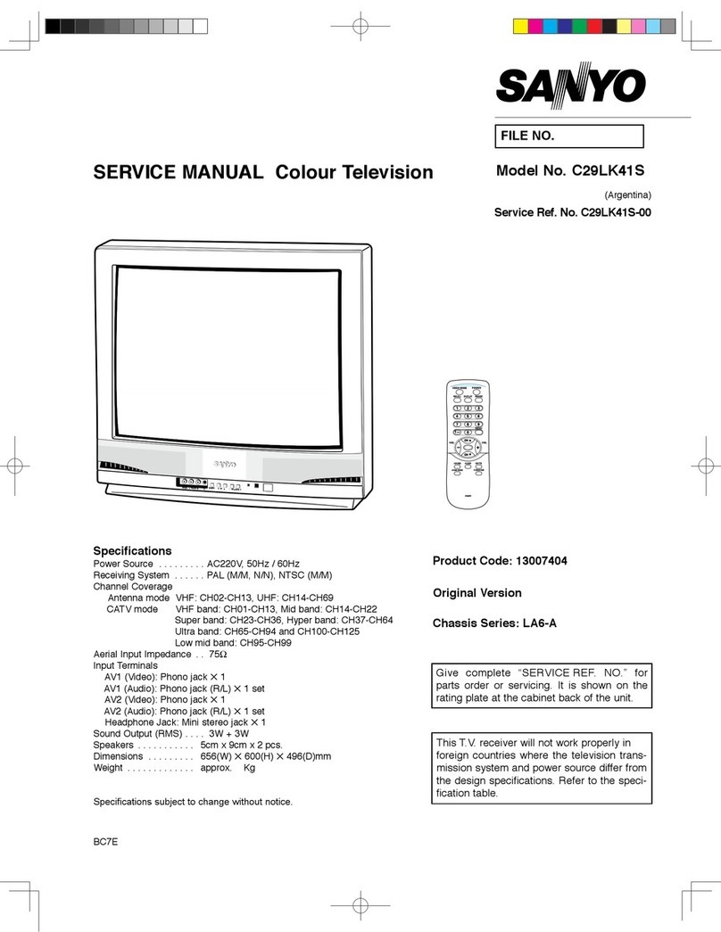
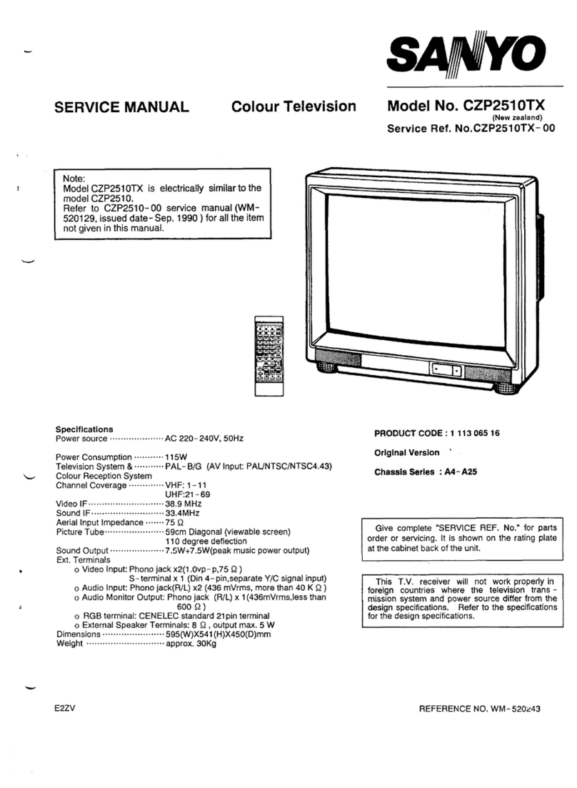
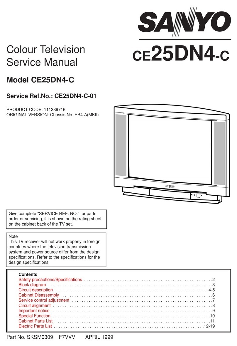
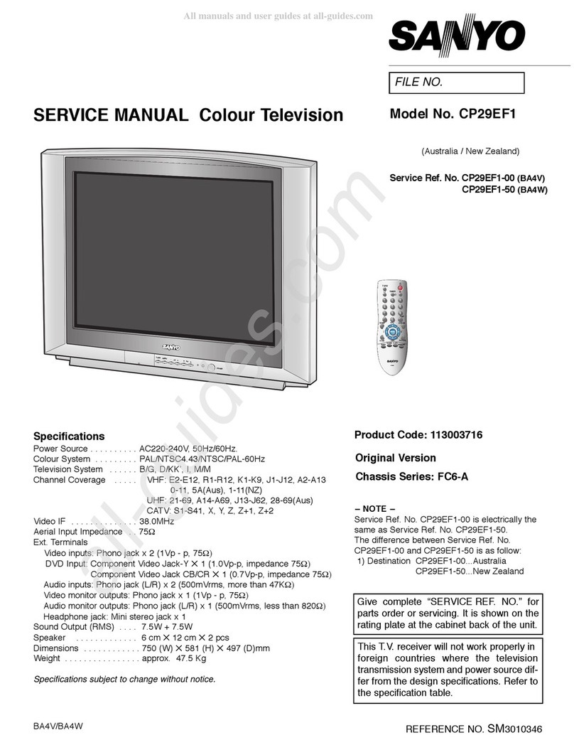
SERVICE MANUAL Colour Television
Product Code: 113020204
Original Version
Chassis Series: LB6-A
BG4E
FILE NO.
Model No. C29FS51
Service Ref. No.
(Argentina)
Give complete “SERVICE REF. NO.” for
parts order or servicing. It is shown on the
rating plate at the cabinet back of the unit.
This T.V. receiver will not work properly in
foreign countries where the television trans-
mission system and power source differ from
the design specifications. Refer to the speci-
fication table.
Specifications
Power Source . . . . . . . . AC220V, 50Hz / 60Hz
Receiving System . . . . . PAL (M/M, N/N), NTSC (M/M)
Channel Coverage
Antenna mode VHF: CH02-CH13, UHF: CH14-CH69
CATV mode VHF band: CH01-CH13, Mid band: CH14-CH22
Super band: CH23-CH36, Hyper band: CH37-CH64
Ultra band: CH65-CH94 and CH100-CH125
Low mid band: CH95-CH99
Video IF . . . . . . . . . . . . . 45.75MHz
Aerial Input Impedance 75Ω
Input Terminals
AV1 (Video): Composite Video Input (Phone Jack) x 1
S-Video Input (Separated Y/C) DIN 4-pin Jack x 1
AV1 (Audio):L/R Stereo Input (Phone Jack) x 1 set
AV2 (Video):Composite Video Input (Phone Jack) x 1
AV2 (Audio):L/R Stereo Input (Phone Jack) x 1 set
DVD (Video): Component Y, CB, CRInput (Phone Jack) x 1 set
DVD (Audio): L/R Stereo Input (Phone Jack) x 1 set
Output Terminals
Video Monitor Output: Phono jack x 1
Audio Monitor Output: L/R Stereo Output (Phone Jack) x 1 set
Headphone Jack: Mini stereo jack x 1
Sound Output (RMS) . . . 5W + 5W
Speaker . . . . . . . . . . . . . . 6cm x 12cm x 2 pcs.
Dimensions . . . . . . . . . . . 750(W) x 590(H) x 416.5(D) mm
Weight . . . . . . . . . . . . . . . approx. 36.5 Kg
Specifications subject to change without notice.

Contents
-2-
SafetyNotice ........................................................................... 2
ChassisBlockDiagram ................................................................... 3
ICBlockDiagrams..................................................................... 4-8
ServiceAdjustments................................................................... 9-18
CabinetPartsList....................................................................... 19
ChassisElectricalPartsList............................................................ 20-27
Safety Notice
SAFETY PRECAUTIONS
1: An isolation transformer should be connected in the
power line between the receiver and the AC line
when a service is performed on the primary of the
converter transformer of the set.
2: Comply with all caution and safety-related notes
provided on the cabinet back, inside the cabinet, on
the chassis or the picture tube.
3: When replacing a chassis in the cabinet, always
be certain that all the protective devices are
installed properly, such as, control knobs, adjust-
ment covers or shields, barriers, isolation resistor-
capacitor networks etc.. Before returning any
television to the customer, the service techni-
cian must be sure that it is completely safe
to operate without danger of electrical shock.
X-RADIATION PRECAUTION
The primary source of X-RADIATION in television receiver is the picture tube. The picture tube is specially con-
structed to limit X-RADIATION emissions. For continued X-RADIATION protection, the replacement tube must
be the same type as the original including suffix letter. Excessive high voltage may produce potentially hazard-
ous X - RADIATION. To avoid such hazards, the high voltage must be maintained within specified limit. Refer
to this service manual, high voltage adjustment for specific high voltage limit. If high voltage exceeds specified
limits, take necessary corrective action. Carefully follow the instructions for + B1 volt power supply adjustment,
and high voltage check to maintain the high voltage within the specified limits.
PRODUCT SAFETY NOTICE
Product safety should be considered when a component replacement is made in any area of a receiver.
Components indicated by mark in the parts list and the schematic diagram designate components in which
safety can be of special significance. It is particularly recommended that only parts designated on the parts list
in this manual be used for component replacement designated by mark . No deviations from resistance
wattage or voltage ratings may be made for replacement items designated by mark .

Chassis Block Diagrams
-3-
SIGNAL PROCESSING CIRCUIT
P10/21
Antenna
CRT DRIVE
TRC
B
/
G/R
W
S
Y
E
K
V
0
0
2+
B
/
G/
R
HV/Fo/Sc
R/C PRE-AMP
TUNER BUS H-OUT DY-H
IF DY-V
(LV76113) HORIZ-DRIVE HORIZ-OUT
SAW TU
OW
Ere
tl
i
f
FBP
E
SU
L
P
T
B
FNI
SUSOC
AV2/DVD/S-VIDEO C VIDEO
V-
/E
-14187AL
(
+VOEDIV
T
UOROTINOM
S-VIDEO Y/AV1-V TU
O-
TR
E
VOEDI
V
PM33
52M
JN
AV1/AV2/DVD AUDIO IN AUDIO BUS
MONITOR OUT AUDIO AUDIO L/R
SPEAKER(L)
SIF OUT
LR
/L
)307
27
AL
(
R)
E
-50
224AL
(R/
L
R
/L
DVD
/2VA
/
1
V
A
PFB2504CT
TUPN
I
O
IDUA
TU
O-
OIDU
ATUP
TUO
O
ID
UA
)NEK
N
A
S
(V0
22C
A
SPEAKER(R)
POWER
LA7846NZ
)
+28V
+32V
+5V
+8V
-16V
+
8
V
+5VRC
+
5VRC
+28V
+140V
10V
10V
+
5V
+16V
+8V
+8V

IC Block Diagrams
-4-
IC601 POWER SUPPLY IC (STRW6754)
FUNCTIONAL BLOCK DIAGRAM

IC Block Diagrams
-5-
IC201 < IF/Video/Chroma/Def./CPU > LA76113

-6-
IC Block Diagrams
IC501<Vertical.Output> LA78141
IC001<AUDIO AMP> LA42205

-7-
IC Block Diagrams
LA72703 BTSC Decoder - Reference Apprication -
10 11 12
Slave Address = 80h ( 1000 000* ) :Pin8=OPEN/GND
Slave Address = 84h ( 1000 010* ) :Pin8=H
Vcc 5V
+
98
65 7
4
21 3
21
2324 22 15 14 13
161719
20 18
MATRIX
MODE
OUT
REGULATOR
+ ++
+
++
+
+
+
4.5M
BPF
LPF
SIF DEMOD
SAP BPF
SAP
DEMOD
L-R
DEMOD ST/SAP
SW
LPF
-6dB
PILOT
CANCELLER
STEREO
PLL
PILOT
DET
PILOT
LEVEL DET
IIC
DECODE
SYSTEM
CONTROL
Offset
Cancell
dbx processor
SAP
DET
4u7 4u7 22u 4u7
OUT(L) OUT(R)
MODE
Monitor
2u2
1u
1u
0.1?
1u
4k7
MUTE
L+R L-R/SAP
ST
SAP
Address
Control
GND
MUTE
Wide RMS DET
Spectral DET
Spectral In
Offset Cancel
0.1u
0.1u
4u7
1u to
0.33u
SIF SIGNAL
from Tuner
Address
Control IIC
DATA
IIC
CLOCK
2u2 22u
Spectral RMS
DET
100u
0.1u
47u
+
10u
+
10u
33n 33n
+
1u
+
560k
LPF
IC3401 LA72703

-8-
IC Block Diagrams
IC1002 NJM2533M
IC1001 TC4052BF

-9-
LB6A VER1.14
NO. NAME DATA
00 RFAGC 17H XX010111
1.11101111 2.11111000
Item No.
Status Register Bit Allocations Data value
General
This set has an On-screen Service Menu system included in the CPU that allows remote operation for most of the
service adjustments.
2. Service Adjustments:
Press the CHANNEL UP/DOWN button on the remote
control handset to select the desired service menu
item you want to adjust.
Use the VOLUME + /
-
button to adjust the data. The
+ or
-
button will increase or decrease the data
sequentially.
3. Exit from the Service Menu
Press the MENU button to turn off the Service Menu
display.
The data which is set in the service mode is stored
into the memory IC automatically.
[ Service Mode Display ]
Service Adjustment-1
1. Enter the Service Menu
While pressing the MENU button on the television, press the Number Key 2 on the remote control unit.
The Service Menu now appear.
IC802 (EEPROM) Replacement
When IC802 (EEPROM) is replaced, IC201 (CPU) will automatically write the initial reference data into IC802 for basic TV operation.
However, the bus data should be checked and some bus data should be set up before attempting the service adjustments. (See
pages 9 ~ 11 for detailed information.)
Service Adjustments
-9-
VOLUME +
VOLUME
-
CHANNEL UP
CHANNEL DOWN
MENU
MENU
Item Name

-10--10-
Service Adjustments
On-screen Service Menu
Following table shows the initial values which have been stored in the CPU ROM, and items for the service adjustments.
When IC802 (EEPROM) is replaced, check the bus data to confirm they are the same as below. The shaded menu should be
checked and be set up or readjusted according to the procedures described in the following pages.
Initial Setup Data marked with an ∗should be changed from Initial Value Data.
No Item Description Initial Data Range
0 RFAGC Align RF AGC threshold 17 00~3F
1 HPHA Alignsynctoybackphase 10 00~1F
2 VSIZE Align vertical amplitude 72 00~7F
3 V DC Align vertical DC bias 22 00~3F
4 VSIFT Align vertical position 08 00~0F
5 V LIN Align vertical linearity 0F 00~1F
6 V SC Align vertical S-correction 16 00~1F
7 VCOMP Align vertical size compensation 07 00~07
8 EWDC Align East/West DC bias 33 00~3F
9 EWAMP Align East/West amplitude 06 00~3F
10 EWTIL Align East/West Trapezoid 32 00~3F
11 EWTOP Align East/West Top corner correction 01 00~0F
12 EWBOT Align East/West Bottom corner correction 02 00~0F
13 EWCSW Select control range for Corner correction 01 00~01
14 HSCMP Align horizontal size compensation 07 00~07
15 HBL Left H-Blanking Control 04 00~07
16 HBR Right H-Blanking Control 05 00~07
17 HPH60 Alignsynctoybackphase(60Hzdata)03 00~3F
18 VSZ60 Align vertical amplitude (60Hz) FF 00~FF
19 VDC60 Align vertical DC bias (60Hz) 00 00~7F
20 VSF60 Align vertical position (60Hz) 1D 00~1F
21 VLI60 Align vertical linearity (60Hz) 00 00~3F
22 VSC60 Align vertical S-correction (60Hz) 00 00~3F
23 VCO60 Align vertical size compensation (60Hz) 00 00~0F
24 EWD60 Align East/West DC bias (60Hz) 01 00~7F
25 EWA60 Align East/West amplitude (60Hz) 7F 00~7F
26 EWT60 Align East/West trapezoid (60Hz) 01 00~7F
27 EWB60 Align East/West Bottom corner correction (60Hz) 02 00~1F
28 EWP60 Align East/West Top corner correction (60Hz) 03 00~1F
29 CSW60 Select control range for Corner correction 00 00~01
30 CMP60 Align horizontal size compensation 03 00~0F
31 T DIS Disable the Test SW & enable Audio / Video Mute SW 01 00~01
32 HFREQ Align ES Sample horizontal frequency (MP is adjusted in the wafer line.)
40 00~7F
33 AFCG Selecthorizontalrstloopgain&H-syncgatingon/off00 00~01
34 AMUTE Disable audio outputs 00 00~01
35 VMUTE Disable video outputs 00 00~01
36 VSZ75 Enable 75% vertical size mode 00 00~01
37 SKILL Force free-run mode 00 00~01
38 VKILL Disable vertical mode 00 00~01
-11--11-
Service Adjustments
No Item Description Initial Data Range
39 V SEP Select vertical sync. Separation sensitivity 00 00~01
40 V RES Select Vertical Reset Timing 00 00~01
41 HLOCK Select Vertical sync system 00 00~01
42 VNSYN Enable IC Test Mode 00 00~01
43 VTEST Select vertical DAC test mode 00 00~03
44 CDMOD Select vertical countdown mode 00 00~07
45 VIL T Vertical deinterlace SW 00 00~01
46 VILT2 Vertical deinterlace SW2 00 00~01
47 VBLKS V blanking control SW 01 00~01
48 FBPSW Select Horizontal blanking operation 01 00~01
49 AFCNG Enable AFC Low gain mode 00 00~01
50 AFC2S Select FBP storage-timer tolerance level 00 00~01
51 CRSBW Service Test Mode (normal/Cross/Black/White) 00 00~03
52 DEINT Deinterlace 00 00~01
53 OETST O/E.TEST 00 00~01
54 RBIAS Align Red OUT DC level 03 00~FF
55 GBIAS Align Green OUT DC level 1E 00~FF
56 BBIAS Align Blue OUT DC level 02 00~FF
57 RDRV Align Red OUT AC level 42 00~7F
58 GDRV Align Green OUT AC level 38 00~7F
59 BDRV Align Blue OUT AC level 3C 00~7F
60 White Balance 00~FF
61 RD xx GD xx BD xx White Balance 00~7F
62 BLDEF Disable RGB output blanking 00 00~01
63 SUBBI Align common RGB DC level 38 00~7F
64 VTRNS Enable data transmission between vertical retrace period 01 00~01
65 DOSDSelect Analogue OSD mode/Digital OSD mode 01 00~01
66 EXCNT Align Ext. RGB amplitude 08 00~0F
67 OSDCN Align OSD AC level 05 00~07
68 RGBSW Select the temperature characteristics for RGB DC output 01 00~01
69 ACLDF Disable Contrast ABL 00 00~01
70 ACLSW Changes inclination of Contrast ABL 00 00~01
71 BABLD Disable brightness ABL 00 00~01
72 MIDDF Disable brightness mid stop 00 00~01
73 BABLT Align brightness ABL threshold 02 00~07
74 RGBT Select RGB DAC test mode 00 00~0F
75 CLKSP Test Mode 00 00~01
76 TSTMD Test Mode 00 00~07
77 VXOAD VXO Adj. 04 00~07
78 MCBCR Chroma Test Mode 00 00~01
79 FODDS Select DDS mode 00 00~01
80 CBCRI Select YCbCr Input 00 00~01
81 CEXT Selected of chroma signal 00 00~01
82 CBYPS Select chroma BPF bypass 00* 00~01
83 CK ON C Kill Mode (0: Enable Killer circuit) 00 00~01

-12--12-
Service Adjustments
No Item Description Initial Data Range
84 CKOFF Disable Killer circuit (for IC Test) 00 00~01
85 CKOPE Select color killer operational level 04 00~07
86 AUTOG Adjust Auto Green level 00 00~07
87 TINTT Set tint center value 01* 00~01
88 WBADJ Auto correct black level 00 00~01
89 IDKIL Select color ident operational level 04 00~07
90 CVCOA Control free Run frequency of chroma VCO 04 00~07
91 CVCOC VCO free run mode 00 00~01
92 FSCSP Select 10 pin output 01 00~01
93 COLSY Select Color System 05* 00~07
94 RBGAI R-Y/B-Y Gain Balance 07 00~0F
95 RBANG R-Y/B-Y Angle 05 00~0F
96 RYLEV R-Y DC Level (White-Balance) 07 00~1F
97 BYLEV B-Y DC level (White-Balance) 08 00~1F
98 GYAMP Adjust G-Y amplitude 08 00~0F
99 HTNCL Select color on/off at Half Tone Mode 00 00~01
100 VXOFR VXO test mode 00 00~01
101 VXOSB VXO test mode 00 00~01
102 IFAGC Disable IF and RF AGC 00 00~01
103 SVOSW Select pin 68 output 00 00~01
104 STRSW Select sound trap ON/OFF 01 00~01
105 VIFSY Select VIF Freq. 38.0/38.9/39.5/45.75/58.75MHz 03 00~07
106 VLEV Align IF video level 04 00~07
107 VCOFQ Align ES Sample IF VCO Frequency. (MP is adjusted in the wafer line) 60 00~FF
108 AMOSW Select pin 70 output 00 00~01
109 DEMTC Select De-emphasis Time Constant 01 00~01
110 FMGAI Select FM Output Level 00 00~01
111 A2SW West Germany Output Level 00 00~01
112 SIFSY Select 4.5/5.5/6.0/6.5 MHz 00 00~03
113 CHCON CH converter measure mode at India 00 00~01
114 FMMUT Disable FM output 00 00~01
115 AFTSE Select AFT sensitivity 10/13/20/40 [mV/KHz] 02 00~03
116 IFTES IF Test mode 00 00~01
117 VCOAD Fine adjust of IFVCO Free run 08 00~0F
118 EWTES Select East/West DAC test mode 00 00~07
119 VOLFL Enablevolumelter01 00~01
120 VOL L Customer L-ch volume control 7F 00~7F
121 AUDSW Select audio input signal 00* 00~03
122 CLKTS Operation CLK test modes 02 00~03
123 SRCNT Select surround effect 00* 00~03
124 DCCUT DC cut test modes 02 00~03
125 MONOM Enable mono input mode 00 00~01
126 VOL R Customer R-ch volume control 7F 00~7F
127 TOATT Enable tone attenuator 00 00~01

-13-
No Item Description Initial Data Range
Service Adjustments
128 TBOST Select Boost/Cut of treble tone control 00* 00~01
129 TRGAI Customer treble gain control 3F* 00~3F
130 PSEST Pseud Stereo 00 00~01
131 BBOST Select Boost/Cut of bass tone control 00 00~01
132 BAGAI Customer bass gain control 3F 00~3F
133 YFLSY Select Y Filter mode 00* 00~03
134 CFLSY Select C Filter mode 00* 00~03
135 Y APF Y APF 00* 00~01
136 YDLAD Y Delay Adjust 04 00~07
137 COGAI Select Coring Gain 03 00~03
138 PRESH Select pre-shoot width 02 00~03
139 OVRSH Select Over-shoot adjustment 02 00~03
140 WPLOP Select White Peak Limiter level. (with Defeat) 00 00~03
141 YGAMS Select Y Gamma start point. (with Defeat) 03 00~03
142 DCRES Select luminace DC restoration 00 00~03
143 BLKST Select Black Stretch Start Point (w/Defeat) 03 00~03
144 BLKGA Select black stretch gain 00 00~03
145 CTRAP Fine adjust of chroma trap 04 00~07
146 CBPF Fine adjust of chroma BPF 01 00~03
147 STRAP Fine adjust of sound trap 03 00~07
148 YGAMG Select Y gamma gain 00 00~03
149 GRAY Service Test Mode (White/Gray) 00 00~01
150 YCMIX Select YC_C Input or 2.2V_DC Input 00 00~01
151 TXTCC Select output by LPF or not 00 00~01
152 VIDEO Video signal selector 00 00~03
153 DLYTE DELAY Test 00 00~01
154 SYSEP Select sync separation threshold level 03 00~07
155 OPT1 OPTION1 ED 00~FF
156 OPTPW AC SW ON Status 00 00~01
157 MHOSD Horizontal position of OSD 2D 00~FF
158 RFCOL Bias Color(RF) 00 00~FF
159 RFBRI Bias Brightness(RF) 00 00~FF
160 RFCON Bias Contrast(RF) 00 00~FF
161 RFSHP Bias Sharpness(RF) 00 00~7F
162 DVDCL Bias Color(DVD) 1F 00~FF
163 DVDBR Bias Brightness(DVD) 00 00~FF
164 DVDCN Bias Contrast(DVD) 00 00~FF
165 DVDSP Bias Sharpness(DVD) 00 00~7F
166 DVDRY Bias R-Y DC LEVEL (DVD) 3A 00~3F
167 DVDBY Bias R-Y DC LEVEL (DVD) 00 00~3F
168 CON60 CONTRAST(60Hz) 00 00~7F
169 BRI60 BRIGHT(60Hz) 00 00~7F
170 COL60 COLOR(60Hz) 00 00~7F
171 RBANT R-Y/B-Y ANGLE (NTSC) 04 00~1F
172 RBAV3 R-Y/B-Y ANGLE (VIDEO) 00 00~1F
173 POMT Power ON Video Mute Time 1A 00~7F

-14-
No Item Description Initial Data Range
Service Adjustments
174 SYSAV Select sync separation threshold level for AV 04 00~07
175 ZSIZ5 ZOOM VSIZE FOR 50HZ 0E 00~7F
176 ZSIZ6 ZOOM VSIZE FOR 60HZ 0E 00~7F
177 ZHPHA ZOOM HPHASE 00 00~1F
178 ZVSCO ZOOM VSC 00 00~1F
179 ZVLIN ZOOM VLIN 00 00~1F
180 ZEAM5 ZOOM EAST AMP FOR 50HZ 02 00~3F
181 ZEAM6 ZOOM EAST AMP FOR 50HZ 02 00~3F
182 ZCOLR ZOOM COLOR 00 00~3F
183 ZCONT ZOOM CONTRAST 00 00~3F
184 ZBRIT ZOOM BRIGHTNESS 00 00~3F
185 ZVPOS ZOOM V POSITION 00 00~0F
186 ZEWDC ZOOM EWDC 00 00~3F
187 ZEWTI ZOOM EAST/WEST TILT 00 00~3F
188 ZEWCT ZOOM East/West Corner Top 02 00~0F
189 ZEWCB ZOOM East/West Corner Bottom 02 00~0F
190 ZVSCP ZOOM V COMP 00 00~07
191 ZHSCP ZOOM H.Size.Comp 00 00~0F
192 CAPCN CAPTION TEXT CONTRAST 06 00~07
193 OPTAV OPTION FOR AV2 AV3 01 00~01
194 OPTFS OPTION OF SLIM OR FLAT 01 00~01
195 OBASS OFFSET OF BASS 00 00~0F
196 OTREB OFFSETOF TREBLE 04 00~0F
197 EWADJ East/West adjustment
198 VEADJ Vertical adjustment
199 ROMCR ROM CORRECTION 00 00~FF

-15--15-
Service Adjustments
Item 00 [RFAGC] AGC
NOTE: Do not attempt this adjustment with weak signal.
1. Tune the receiver to most clearest (or strongest) VHF
station in your area. Set the brightness and contrast
controls to maximum. Set the colour control to mini-
mum.
2. Select Item No. 01 [RFAGC] in the service mode.
3. Change value until the snow noise just disappears.
4. Exit from the service mode.
Item 01 [H-PHA] HORIZONTAL CENTRE
1. Receive a monochrome circular pattern.
2. Set the brightness and contrast to normal.
3. Select Item No. 02 [H-PHA] in the service mode.
4. Change value to be optimum horizontal centre posi-
tion.
5. Exit from the service mode.
1. Receive a monochrome circular pattern.
2. Set the brightness to normal and contrast to maximum.
3. Select Item No. 02 [VSIZE] in the service mode.
4. Change value to be optimum vertical size.
5. Exit from the service mode.
1. Receive a monochrome circular pattern.
2. Set the brightness and contrast to maximum.
3. Select Item No. 03 [V-DC] in the service mode.
4. Change value to be optimum vertical centre position.
5. Exit from the service mode.
1. Receive a monochrome circular pattern.
2. Set the brightness and contrast to maximum.
3. Select Item No. 04 [VSHIFT] in the service mode.
4. Change value to be optimum vertical centre position.
5. Exit from the service mode.
1. Receive a monochrome circular pattern.
2. Set the brightness and contrast to maximum.
3. Select Item No.08 [EWDC] in the service mode.
4. Change value to be proper horizontal width.
5. Exit from the service mode.
1. Receive a monochrome circular pattern.
2. Set the brightness and contrast to normal.
3. Select Item No. 157 [MHOSD] in the service mode.
4. Change value to be proper OSD horizontal position.
5. Exit from the service mode.
Horizontal centre
Vertical centre
Vertical size
Important Notice:
Do not attempt to adjust service adjustments not listed on below otherwise it may cause loss of performance and for
correct operation.
Item 03 [V-DC] VERTICAL CENTRE
Item 04 [VSHIFT] VERTICAL CENTRE
Item 08 [EWDC] HORIZONTAL WIDTH
Item 02 [VSIZE] VERTICAL SIZE
Item 157 [MHOSD] OSD H-POSITION

-16--16-
Service Adjustments
Items 35-42 GREY SCALE
1. Receive a monochrome circular pattern.
2. Set the brightness and colour to normal, contrast to maximum.
3. Enter to the service mode.
4. Set Item-54 RBIAS, 55 GBIAS and 56 BBIAS mode to 03, 1E and 02. Set Item-57 RDRV and 58 GDRV mode to
42 and 38, 59 BDRV to 3C.
5. Select Item-60 mode to be one horizontal scanning line and turn the screen volume on the FBT to obtain just vis-
ible one coloured line.
6. Press the 1 (Red Bias +), 4 (Red Bias
-
), 2 (Green Bias +), 5 (Green Bias
-
), 3 (Blue Bias +) or 6 (Blue Bias
-
)
button to adjust the brightness of each colour until a dim white line produced. Please see the control button alloca-
tions in this mode.
7. Select Item-61 DRV mode to enter the white balance adjusting mode.
8. Press the 7 (Red Drive +), RECALL (Red Drive
-
), 8 (Green Drive +), 0 (Green Drive
-
), 9 (Blue Drive +) or
SLEEP (Blue Drive
-
) button alternately to produce normal black and white picture.
9. Exit from the service mode.
10. Check for proper grey scale tracking at all brightness levels.
NOTE: If the grey scale adjustment is made after picture tube replacement, check the high voltage.
Red Bias
-
Red Bias +
Green Bias
-
Blue Bias +
Green Drive
-
Green Drive +
Green Bias +
Blue Bias
-
Press the MENU but-
ton to exit from service
mode
Red Drive
-
Blue Drive +
Blue Drive
-
Red Drive +
MAIN BOARD
SCREEN VR
(Under side)

-17--17-
Service Adjustments
It will return to normal TV mode if no opeation for 5
seconds.
FINE TUNING
-
+
Fine tuning service mode
Fine tuning data value will be automatically stored in
memory.
Service Adjustment-3
FINE TUNING
This adjustment is used to do a fine tuning of the channels with poor reception after they have been stored by the
automatic tuning.
This function is available for one channel only and the fine-tuned channel is memorized into IC802 (EEPROM).
1. Enter the Service Menu
While pressing the MENU button on the television,
press the “4” or MENU button on the remote control
unit. The Service Menu now appear.
2. Service Adjustments:
Press and hold the VOLUME (+/
-
)button on the
remote control handset or TV set to make fine tuning
adjustment. Press and hold the + button for higher
frequency tuning, and press and hold the
-
for lower
frequency tuning.
[ Entering the Service Menu ]
[ Service Adjustment ]
[ Exit from the Service Menu ]
VOLUME +
VOLUME
-
MENU

-18--18-
Service Adjustments
Service Adjustment-4
FOCUS ADJUSTMENT
1. Receive the monochrome circular pattern.
2. Set the brightness to normal and contrast
to maximum.
3. Adjust the focus control on the F.B.T. for
the best focus on the screen centre.
FOCUS VR (Upper side)
This TV set has a built-in power supply protection circuit.
It is provided to protect the TV set in case of a power supply circuit malfunctions. When something abnormality occurs
during TV reception, the TV set goes to the stand-by mode.
When an abnormality occurs during TV reception, it causes pin 23 of the CPU to go continually Low voltage for
about one second. The CPU detects that this has occurred and outputs the signal from pin 36 to switch off the
power supply lines.
Releasing the protective circuit and restoring power supply
To release the protective circuit and restore power supply, turn the power to the TV set OFF and then ON again via
either the main power switch or the ON-OFF button on the remote control. This will work only if the power supply trou-
ble was temporary. If there is permanent trouble such as a damaged circuit, power cannot be restored and the circuit
will have to be repaired.
Protection Circuit
HIGH VOLTAGE CHECK
Note: +B (+140V) Voltage and Grayscale Adjustment must be completed before attempting High Voltage Check.
1. Connect high voltage voltmeter negative lead to ground, and connect + lead to anode of picture tube.
2. Tune receiver to an active channel and confirm TV is operating properly.
3. The high voltage must be 28KV ± 1KV and less than 29.5KV at 0 beam current (Brightness and contrast minimum
setting).
Note: If the picture tube is replaced, check the high voltage.
+B POWER SUPPLY CHECK
1. Connect a DC voltmeter to TP-B and the
ground.
2. Set the brightness to normal and contrast
to maximum.
3. Tune the receiver to an active channel
and synchronized picture.
4. The +B voltage must be 140± 2.0 volt DC.
TP-B

-19--19-
Cabinet Parts List
Note: Parts order must contain Service Ref. No., Part No., and descriptions.
11 12
9
10
1 1AA2BUM0579-- BUTTON POWER
1S00620 COIL SPRING-D8HA
2 1AA2DEM0479-- DEC IND
3 1AA2DDM0203-- DOOR FRONT
4 1AA2BUM0595-- BUTTON UNITED
5 1AV2LA9FA01-- LATCH PUSH
or 1LG2LA9FA01-- LATCH PUSH
6 1AA2DES0996-- DEC SHEET
7 1AA2CAM0684-- CABINET FRONT
8 1LG2BAA0009-- BADGE,SANYO*53.5X12L53.5
9 1AA2CBM0484-- CABINET BACK
10 1AA6P4S3558-- LABEL RATING
11 1AV0U10B30302 ASSY,REMOCON JXMTF
12 1AV4U19B00700 ANTENNA CONVERTER
1AV4U19B00701 ANTENNA CONVERTER
1LG6P1P0421-- INSTRUCTION MANUAL-BF5E
Key No. Part No. Description Key No. Part No. Description
1
2
4
8
7
5
6
3

-20-
Chassis Electrical Parts List
Product safety should be considered when a component replacement is made in any area of a receiver.
Components indicated by a
!
mark in this parts list and the circuit diagram show components whose value have
special significance to product safety. It is particularly recommended that only parts specified on the following parts
list be used for components replacement pointed out by the mark.
Note: Parts order must contain Service Ref. No., Part No., and descriptions. The main PCB unit will be supplied without tuner and
flyback transformer. They should be ordered separately.
Read description in the Capacitor and Resistor as follows:
CAPACITOR
CERAMIC 100P K 50V
Rated Voltage
Tolerance Symbols:
Less than 10pF
A : Not specified B : ±0.1pFC : ±0.25pF
D : ±0.5pFF : ±1PFG : ±2pF
R : ±0.25-0pFS : ±0-0.25pFE : +0-1pF
More than 10pF
A : Not specified B : ±0.1%C : ±0.25%
D : ±0.5%F : ±1%G : ±2%
H : ±3%J : ±5%K : ±10%
L : ±15%M : ±20%N : ±30%
P : +100-0%Q : +30-10%T : +50-10%
U : +75-10%V : +20-10%W : +100-10%
X : +40-20%Y : +150-10%Z : +80-20%
Rated value: P=pico farad, U=micro farad
Material:
CERAMIC...........Ceramic
MT-PAPER.........Metallized Paper
POLYESTER......Polyester
MT-POLYEST.....Metallized Polyester
POLYPRO..........Polypropylene
MT-POLYPRO....Metallized Polypropylene
COMPO FILM.....Composite film
MT-COMPO........Metallized Composite
STYRENE...........Styrene
TA-SOLID...........Tantalum Solid
AL-SOLID...........Aluminium Solid
ELECT................Electrolytic
NP-ELECT..........Non-polarised Electrolytic
OS-SOLID..........Aluminium Solid with Organic Semiconductive Electrolytic
DL-ELECT..........Double Layered Electrolytic
RESISTOR
CARBON 4.7K J A 1/4W
Rated Wattage
Performance Symbols:
A: General B: Non flammable Z: Low noise
Other: Temperature coefficient
Tolerance Symbols:
A: ±0.05% B: ±0.1% C: ±0.25% D: ±0.5%
F: ±1% G: ±2% J: ±5% K: ±10%
M: ±20% P: +5-15%
Rated value, ohms:
K: 1,000, M: 1,000,000
Material:
CARBON...........Carbon
MT-FILM............Metal Film
OXIDE-MT.........Oxide Metal Film
SOLID................Composition
MT-GLAZE.........Metal Glaze
WIRE WOUND...Wire Wound
CERAMIC RES..Ceramic
FUSIBLE RES....Fusible
NOTES:
-20-
Table of contents
Other Sanyo TV manuals

Sanyo
Sanyo CZP2900TX User manual

Sanyo
Sanyo C29LK39S User manual

Sanyo
Sanyo CZP2141TX User manual

Sanyo
Sanyo AVM-3650G User manual

Sanyo
Sanyo CP21SA1 User manual

Sanyo
Sanyo DP52848 User manual

Sanyo
Sanyo CA21XS2S User manual

Sanyo
Sanyo CPP2910 User manual

Sanyo
Sanyo AVM-3259S User manual

Sanyo
Sanyo C20VT11-M User manual

Sanyo
Sanyo C20LB18S User manual

Sanyo
Sanyo CE29FFV1-F User manual

Sanyo
Sanyo PDP-42XR8DA User manual

Sanyo
Sanyo CA29YS2S User manual

Sanyo
Sanyo C29ZK80 User manual

Sanyo
Sanyo CE21KF8R User manual

Sanyo
Sanyo DP32640 - 31.5" Diagonal LCD HDTV 720p User manual

Sanyo
Sanyo Vizzon HT27547 User manual

Sanyo
Sanyo DS27830 User manual

Sanyo
Sanyo C29ZK80TX User manual