Index
1 Safety instructions................................................................................................................................................................................. 1
2 WARNING ............................................................................................................................................................................................ 1
3 Precaution against X-Rays.................................................................................................................................................................... 1
4 Recommendations to protect our environment...................................................................................................................................... 1
5 Technical characteristics....................................................................................................................................................................... 2
6 Safety ................................................................................................................................................................................................... 2
7 EMC (Electromagnetic Compatibility).................................................................................................................................................... 2
8 Factory special mode............................................................................................................................................................................ 3
9 “HOTEL” and “RENTAL” modes............................................................................................................................................................ 3
10 Automatic channel search reactivating ............................................................................................................................................. 3
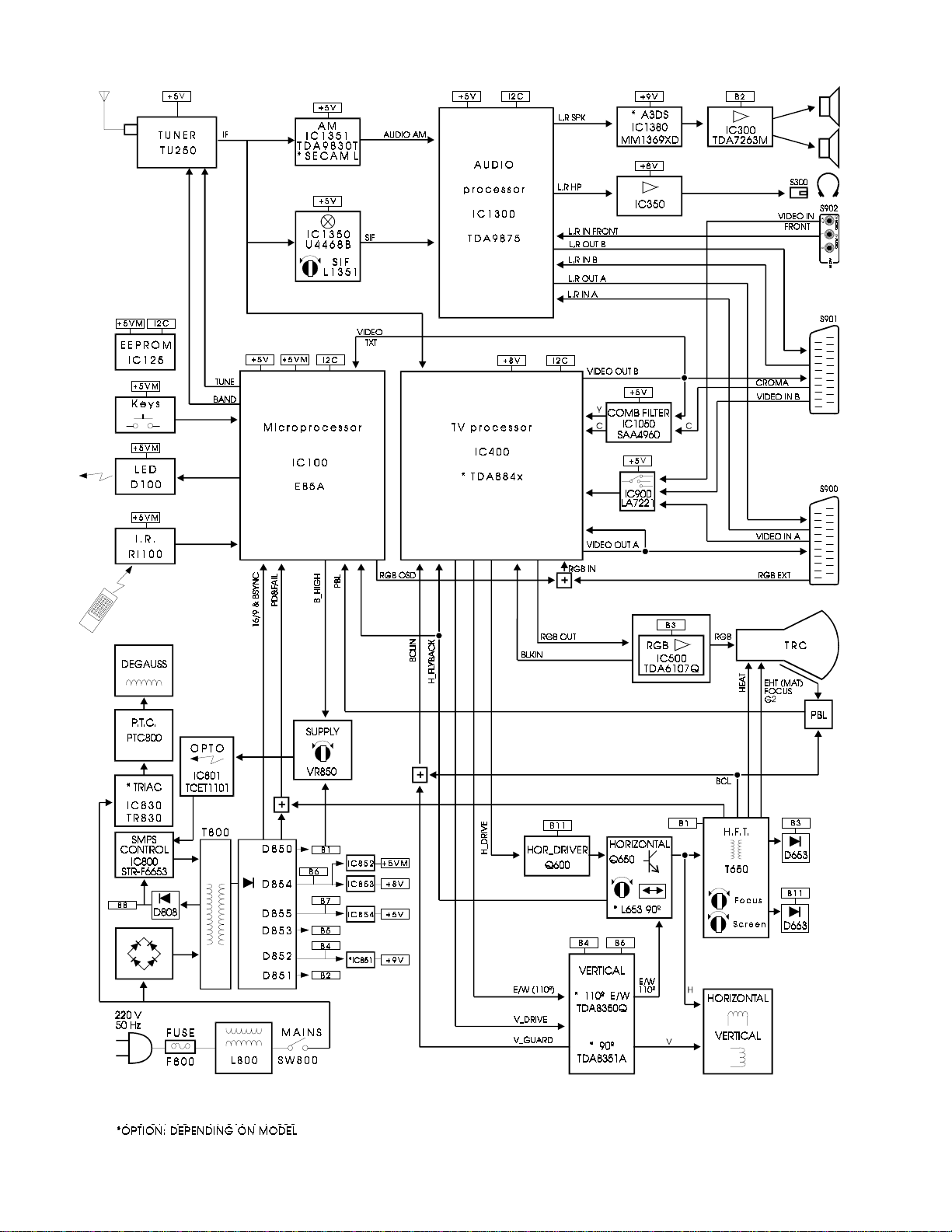
11 Block diagram................................................................................................................................................................................... 4
12 Power supply.................................................................................................................................................................................... 5
13 Microprocessor and Teletext............................................................................................................................................................. 5
14 Video processor/Comb filter.............................................................................................................................................................. 5
14.1 Video Intermediate Frequency Section......................................................................................................................................... 5
14.2 Horizontal and vertical synchronisation ........................................................................................................................................ 5
14.3 Geometry..................................................................................................................................................................................... 6
14.4 Filters and video switches ............................................................................................................................................................ 6
14.5 Colour decoder............................................................................................................................................................................. 6
14.6 RGB Processing........................................................................................................................................................................... 6
14.7 RGB Control................................................................................................................................................................................. 7
14.8 Supply and bandgap decoupling................................................................................................................................................... 7
15 Audio processor/A3D Surround/Output amplifiers/Sound IF............................................................................................................. 7
16 Service menu.................................................................................................................................................................................... 8
17 Adjustment and repair procedures.................................................................................................................................................. 10
17.1 Notes about the adjustment:....................................................................................................................................................... 10
17.2 Switch-on sequence................................................................................................................................................................... 11
17.3 Protect modes and failure indication........................................................................................................................................... 11
17.4 Protect mode inhibition............................................................................................................................................................... 11
17.5 Power supply repair procedure................................................................................................................................................... 11
17.6 Non-volatile memory (NVM) replacement, IC125........................................................................................................................ 11
18 Failure location flow-charts............................................................................................................................................................. 12
19 Complete PCB codes for after sales service................................................................................................................................... 15
20 CHASSIS ELECTRICAL PARTS LIST............................................................................................................................................ 16
21 CABINET PARTS LIST 21” ............................................................................................................................................................ 17
22 CABINET PARTS LIST 25” ............................................................................................................................................................ 18
23 CABINET PARTS LIST 28” ............................................................................................................................................................ 19
24 Parts List ........................................................................................................................................................................................ 20
CE28FV2-E
CE25FV2-E
CE21FV2-E
Service Manual Models:
CRT 28” A59EAK071X11
CRT 25” A66EAK071X11
CRT 21” A51EAL155X10
CRT 21” A51EAL155X11
CHASSIS No 2103
EB5-A
Colour Television
Ref. NºMS CE25FV2-E
13/01/2000
Give complete “SERVICE PART No” for parts order or
servicing, it is shown on the rating sheet on the cabinet
back of the TV set.
Note
This TV receiver will not work properly in foreign countries
where the television transmission system and power
source differ from the design specifications. Refer to the
specifications for the design specifications.