Sanyo CE28H1A-C-00 User manual

Part Number: SKSM0274 Service Manual EH1 chassis
Colour Television Service Manual
Give complete "SERVICE REF. NO." for parts order
or servicing, it is shown on the rating sheet on the
cabinet back of the TV set.
Note
This TV receiver will not work properly in foreign
countries where the television transmission system
and power source differ from the design specifications.
Refer to the specifications for the design specifications
Contents
Safety precautions . . . . . . . . . . . . . . . . . . . . . . . . . . . . . . . . . . . . . . . . . . . . . . . . . . . . . . . . . . . . . . . . . . . . .2
Specifications . . . . . . . . . . . . . . . . . . . . . . . . . . . . . . . . . . . . . . . . . . . . . . . . . . . . . . . . . . . . . . . . . . . . . . . . .2
Circuit description . . . . . . . . . . . . . . . . . . . . . . . . . . . . . . . . . . . . . . . . . . . . . . . . . . . . . . . . . . . . . . . . . . . .3-7
Disassembly . . . . . . . . . . . . . . . . . . . . . . . . . . . . . . . . . . . . . . . . . . . . . . . . . . . . . . . . . . . . . . . . . . . . . . . . . .8
Service adjustments . . . . . . . . . . . . . . . . . . . . . . . . . . . . . . . . . . . . . . . . . . . . . . . . . . . . . . . . . . . . . . . . .9-13
Component locations . . . . . . . . . . . . . . . . . . . . . . . . . . . . . . . . . . . . . . . . . . . . . . . . . . . . . . . . . . . . . . .14-20
Special functions . . . . . . . . . . . . . . . . . . . . . . . . . . . . . . . . . . . . . . . . . . . . . . . . . . . . . . . . . . . . . . . . . . . . .21
Waveforms & voltages . . . . . . . . . . . . . . . . . . . . . . . . . . . . . . . . . . . . . . . . . . . . . . . . . . . . . . . . . . . . . .22-27
Service parts lists . . . . . . . . . . . . . . . . . . . . . . . . . . . . . . . . . . . . . . . . . . . . . . . . . . . . . . . . . . . . . . . . . .28-51
Schematic diagram
28H1A (CE28H1A-C) [Europe]
Chassis:
EH1-A
Service Ref. No.:
CE28H1A-C-00
For further technical information, please refer to the
training manual EH1 chassis, ref. No. TI520015.

-2- Service Manual EH1 chassis
SAFETY PRECAUTION
X-RADIATION PRECAUTION
The primary source of X-RADIATION in the television receiver is the picture tube. The picture tube is specially
constructed to limit X-RADIATION emissions. For continued X-RADIATION protection, the replacement tube must
be the same type as the original including suffix letter. Excessive high voltage may produce potentially hazardous
X-RADIATION. To avoid such hazards, the high voltage must be maintained within specified limit. Refer to this
service manual, high voltage adjustment for specific high voltage limit. If high voltage exceeds specified limits,
take necessary corrective action. Carefully follow the instructions for +B1 volt power supply adjustment, and high
voltage adjustment to maintain the high voltage within the specified limits.
PRODUCT SAFETY NOTICE
SPECIFICATIONS
Power Source AC220 ~ 240V, 50Hz
Television System BG
Colour System PAL
Receiving Channels VHF: E2 ~ E12
CATV: X, Y, Z, S1 ~ S41
UHF: 21 ~ 69
Aerial Input Impedance 75 ohm
Speakers 2 x 8 ohm
Sound Output 8.5 W (CONT)
Picture Tube 70cm diagonal, 110°
Visible Picture 66cm
Dimensions (WxHxD) 736 x 596 x 500mm
Weight 33.8 kg
1: An isolation transformer should be connected in the
power line between the receiver and the AC line
when a service is performed on the primary of the
converter transformer of the set.
2: Comply with all caution and safety-related notes
provided on the cabinet back, inside the cabinet, on
the chassis or the picture tube.
Product safety should be considered when a component replacement is made in any area of a receiver.
Components indicated by mark in the parts list and the schematic diagram designate components in which
safety can be of special significance. It is particularly recommended that only parts designated on the parts list in
this manual be used for component replacement designated by mark . No deviations from resistance wattage
or voltage ratings may be made for replacement items designated by mark .
!
!
!
3: When replacing a chassis in the cabinet, always be
certain that all the protective devices are installed
properly, such as, control knobs, adjustment covers or
shields, barriers, isolation resistor-capacitor networks
etc. Before returning any television to the customer,
the service technician must be sure that it is
completely safe to operate without danger of electrical
shock.

-3-
Service Manual EH1 chassis
This is a diagram for all models and therefore differs slightly from the actual block diagram.
Tuner
IF
stage
A2 stereo
decoder NICAM
decoder Audio
Processor
3D surround
processor
Audio
output Speakers
AV selector
Video
chroma
deflection
demodulator
Double
scan
converter
Video
Aperture
Control &
Matrix
Video
output
System
Control
CPU
memory
teletext
decoder
H/V sync.
driver
Vertical drive
&
waveform
controller
Vertical
output
Horizontal drive
&
output
I2C bus
D/A
High-voltage
CRT
Volume
Bass
Treble
Balance
Mute
AV mode
I2C Bus control
H-Centring
V-Centring
SIF carrier
L, R L, R
L, R L, R
L, R
L, R
L, R
AV4(Front)
(Scart)
AV1
AV4
AV3
AV2
Y/CVBS
C
Y
H/V sync
R-Y
B-Y
2Y
2R-Y
2B-Y
VDHD
VD
H-Drive
V-drive
DY
R
G
B
IK
H.V
RGB
Colour
Brightness
Contrast
Tint
Sharpness
CIRCUIT DESCRIPTION
Outline

-4- Service Manual EH1 chassis
This chassis consists of the tuner, IF detector, audio
signal processor, video signal processor, AV selector,
double scan converter, vertical deflection, horizontal
deflection and system control circuit that controls all of
the circuit on this chassis.
The RF(radio Frequency) signal input to the tuner from
the aerial is converted to the IF(Intermediate Frequency)
signal in the tuner stage, and then, the composite video
(CVBS) signal and the SIF carrier signal are extracted at
the IF detector circuit.
The SIF carrier signal is applied to the A2 stereo
demodulator circuit and Nicam stereo demodulator circuit
respectively. The A2 stereo demodulator detects the SIF
signal (5.5MHz=Main channel, 5.74MHz=Sub channel)
input, and sends out the A2 stereo audio signals output
to the Nicam decoder circuit, and also judges that the
receiving signal is stereo or monaural, and sends out the
result to the CPU via I2C bus lines. The Nicam decoder
decodes the SIF signal (5.85MHz components) input and
obtains the Nicam stereo audio signals output. This IC
also sends out the status (Nicam or not) to the CPU via
the I2C bus lines. The obtained A2 stereo or Nicam
stereo audio signals are selected by the CPU via the I2C
bus and supplied to the audio processor circuit as TV
audio signal.
In the video signal processing stage, video signal output
from the IF detector circuit is supplied to the AV selector
circuit as TV video signal. The AV selector circuit selects
the output video signal from the input signal of TV video,
scart video and front video signal by the CPU via I2C
bus. The selected video signal is sent to the
video/chroma demodulator circuit. The video/chroma
demodulator demodulates the video signal or Y and C
signal and outputs the colour differential signal R-Y, B-Y,
Y, H-sync and V-sync signal and supplies them to the
double scan converter circuit.
The double scan converted Y, R-Y and B-Y signals are
applied to the aperture control and RGB matrix circuit.
The RGB original colour signal which are obtained at the
RGB matrix circuit drive the video output circuit. This
video output circuit also controls the automatic cut-off by
feeding back the AKB(Auto-Kine Bias) pulse on the RGB
signal during the vertical blanking period to the RGB
matrix and video control circuit.
The H-sync and V-sync signals are applied to the H/V
sync driver circuit to generate the drive signals for each
output circuit. In the vertical signal control circuit, the
vertical sawtooth signal applied to the vertical output
circuit is waveform-shaped to compensate the raster
distortion.
On the other hand, the audio processor circuit selects the
output audio signal from input signals of TV audio, front
audio and scart audio by the CPU via I2C bus. The
selected audio signals are sent to the 3D surround
processing circuit for adding the 3D surround effects.
These signals are again input to the audio processor IC,
and are controlled in volume, bass, treble, balance and
sound mute by the CPU via I2C bus. The controlled audio
signals are supplied to the audio output circuit to drive
the loudspeakers.
Main signal flow

-5-
Service Manual EH1 chassis
Tu
Q105
X103
SAW IC101
Q112 Q1231
Q1232
IC1200
Q1204
Q1201
Q1207
Q1202
Q1208
AV1 AV2 AV3 AV4
IC801
IC202 IC204 IC201
Double Scan
Converter
Video
Aperture
Control &
matrix
Q211
Q212
Q213
Q711
Q721
Q731
Q831
Q832
Q833
IC206
Q836
IC711
IC721
IC731
3
58
3
58
3
58
8
721
48
1
9
11
13
33
40
37
45
43
25
26
14
13
12
1
2
3
4
18
19
20
21
11
17
V-sync
H-sync
YR-Y
B-Y
Y/CVBS
C
CVBS
Video
V
Y
C
TV-out
Video
Video
R-Y
B-Y
R-Y
B-Y
16
14
12
11
R,G,B,BLK
AV2-R,G,B
AV2-BLK
R,G,B
Teletext
OSD R,G,B
13
12
11
10
6
7
8
15
2
3
4
13
11
10 12
IC207
11
BLK
10 12
14
9
5
BLK
H-sync
V-sync
Y
R-Y
B-Y
2Y
2R-Y
2B-Y
R
G
B
IK
BLK
RGB
23
24
35
34
33
32
Monitor-out
VR1201
(Front)
30
4.43MHz
osc.
IF
CPU
AV Selector
Video
Chroma
Def.
RGB
SW
Video Out
CVBS
Video signal rooting
Tu X102
IC101
IF
Q107
6
522 Q3483
Q3484
Q3483
Q3484
Q3432
Q3431
5.5MHz
5.74MHz
1
15
8
7
7
8
14
13
16
7
29
8
15 3
5
9
24
1
23
13
11
5
3
14
8
10
23
18
15
2 4 7 12
1
32
28
30
AV Selector Circuit
BACK BOARD
LRL
R
L
R
FRONT AV
SCART
IC3431
Audio Processor
IC3531
3D Surround
Processor
IC3521
Equaliser
IC001
Audio Output
IC3800
A2 Stereo
Sound Demo.
IC3401
A2 Stereo
FM Decoder IC3451
NICAM Decoder
AF1
AF2
L
R
L
R
R
R
LL
R
L
L
R
L
R
SIF carrier
Main
Sub
I2C BUS
I2C BUS
20 1 49
50 16
17
From CPU
Audio signal rooting

-6- Service Manual EH1 chassis
IC1200
CXA1855S BACK BORAD
44 AV selector
IC2351
CXD2018QP
IC2201
AN5390FBS
IC2101
AN5395FBP
IC2206
LA6393M
IC2203
TC74HC123AF IC2205
TC7WH74FU
IC2202
TC7W04F
IC2102
CXA1315P
IC675
B5V
IC2341
MC74HC74AF IC2351
CXD2018QP IC2361
LA6358M
IC801
QXXAV8079
IC802
24LC04
IC207
M74L532P
IC7213
CXD2000Q IC7203 IC7204 IC7205 IC7206
IC7207 IC7208 IC7209 IC7211
IC7212 IC7215 IC7221 IC7222
IC7223
IC3401
TDA9840 IC3800
TDA9821 IC3451
SAA7283
Tuner IC101
LA7577N IC350
LA7210
IC2391
LA6458M
IC205
MC74HC74AN
IC206
MC74HC04AN
IC2371
LA6458M IC2381
LA6458M
IC7201
TLC5733IPM
IC7214
QXXAAC2138
5V
8V
IC001
TA8216H
5V
Q681
RC5V
IC361
UPC1377C IC2311
LA6393M IC2331
CXA1315P
IC677
D5V 5V
IC672
A5V 5V
24V
IC7301
5V
IC676
B9V 9V
15V
IC674
A12V 12V
POWER SUPPLY
CIRCUIT
Memory
44
39
14
8
14 V-Driver 8
21 816
888
444
H/V sync.det. I2C bus D/A
CPU
59 816
88
Video
Sharpness
19 16
I2C bus D/A
Matrix&
controller
12V
-12V
SUB DEF. BOARD
VIDEO BOARD
DOUBLE SCAN CONVERTER BOARD
Logic ICs
73
14,26
30,35
51,62
8bit A/D converter
30,32
42,43 D/A converter
Double scan
converter
14
14
18 14 3,26,36
A2 stereo decoder NICAM stereo decoder
99
IF demodulator Sync. detector
FRONT BOARD
C9V 9V
IC678
IC3531
MM1369AD IC3521
M5228P
Tuning voltage
IC202
TDA9143 IC203
LA6393 IC201
TDA8601 IC204
TDA4665
IC3431
TDA9860
Horiz.Drive &
Output Circuit
IC673
A8V 8V
35V
IC671
A9V 9V
15V
IC652
A12V 12V
POWER SUPPLY
CIRCUIT
5V
IC711
TDA6111Q IC721
TDA6111Q IC731
TDA6111Q
IC653
-12V -12V
-16V
137V
IC501
LA7846N
High Voltage
CRT
Heater
65V
200V
15V
-15V
33V
T403
T402
4
72
V-Output
6
66
2
2
2Video Output
CRT BOARD
4
24
78161, 9
3D surround
Sound
controller
RGB selector
Video/chroma/def.
1H delay
12V
-12V
To Sub Def. Board
Power supply rooting

-7-
Service Manual EH1 chassis
1
2
3
4
5
6
7
8
9
10
11
12
13
14
15
16
17
18
19
20
21
22
23
24
25
26
52
51
50
49
48
47
46
45
44
43
42
41
40
39
38
37
36
35
34
33
32
31
30
29
28
27
BAND1
BAND2
BAND3
X'TAL
OSC for
CPU
KEY SCAN & OP
SIF SW L/L'
POWER ON/OFF
AFT-S
BLUE (OSD)
GREEN (OSD)
RED (OSD)
BLANKING (OSD)
H-SYNC
V-SYNC
RESET
AKB/2V
SYNC IDENT
RC SIGNAL
SOUND MUTE
IC101
IF
MEMORY
IC802
KEY SWITCHES
POWER
SUPPLY
CIRCUIT
IC801
CPU
D615
TUNER
TU
VL
VH
U
TUNING
IF-AGC
FRONT AV SW.
50/60Hz SW
STILL
DECAUS. COIL SW.
LED DRIVE
IGNORE
CVBS TV
CVBS AV
FRAME
VIDEO MUTE
I2C BUS SCL
I2C BUS SDA
SCL-NVM
SDA-NVM
AFT-S
VERTICAL
DEFLECTION
CIRCUIT
HORIZONTAL
DEFLECTION
CIRCUIT
POWER FAILURE DETECTION
Q801
Q103/Q802
Q101/Q804
Q102/Q803
Q604
Q104
Q111
IF-AGC
I2C BUS Control
IC001
AUDIO OUT
IC350
SYNC ID VIDEO-in
DOUBLE
SCAN
CONVERTER
VIDEO
CONTROLLER
IC202
VIDEO
CHRAMA
DEF.
Y
R-Y
B-Y
To Scan Converter
VL
VH
U
STANDBY
ON
NORMAL
ON
60Hz
ON
MUTE
SYNC ON
MUTE ON
ON
OP
System control

-8- Service Manual EH1 chassis
DISASSEMBLY
CABINET BACK DISASSEMBLY
1. Remove 10 screws(A) and 4 screws(B)
2. Pull out the cabinet back.
PLACING THE CHASSIS TO SERVICE
POSITION
1. Remove 2 screws (C).
2. Release the wires at hooks(D) and hooks(E).
3. Remove an AC cord holder(F).
4. Turn the chassis to the service position as
shown in the picture.
5. Fix the chassis with a screw(C)
(C)
(A)
(B)
(C)
(C) (E)
(D)
AC cord
holder(F)
(B)
(A)
(A)
(A)
(A) (A)
(A)
(A)
(A)
(A)

SERVICE ADJUSTMENTS
[After replacing the Memory IC (IC802)]
The memory IC, IC802, stores the service adjustments data for each circuit, therefore, when the memory IC is
replaced, it should be readjusted the following adjustments and confirmed initial data value, refer to the adjustment
table on next page.
Adjustments Service Mode
Stereo separation adjustment Item 000, Item 001
Vertical Centring Item 005
Vertical Height Item 006
Horizontal Centring Item 009
Horizontal Width Item 010
White Balance Item 034, Item 035
DCS Gain Item 057
Auto Setup Option setting Item 069
Enter to the Service Mode
■Press and hold the Function button on the RC handset and then press the Prog + button on the TV set.
+ To select the adjustment item, use the Prog+ or Prog- button. The selected item is indicated in red.
+ To change the service data, use the Level - or Level + button.
+ The data which is set in the service mode is stored into the memory IC automatically.
Exit from the Service Mode
■Turn off the TV set by using the Mains switch.
ADJUST DATA
+000 K1 +001
+001 K2 -006
+003 STID +000
ADJUST DATA
+000 K1 +001
+001 K2 -006
+003 STID +000
Item service data
Note: Some items of the service adjustments for this chassis are controlled by the CPU, IC801, and the
adjustments are carried out by using the RC handset.
-9-
Service Manual EH1 chassis

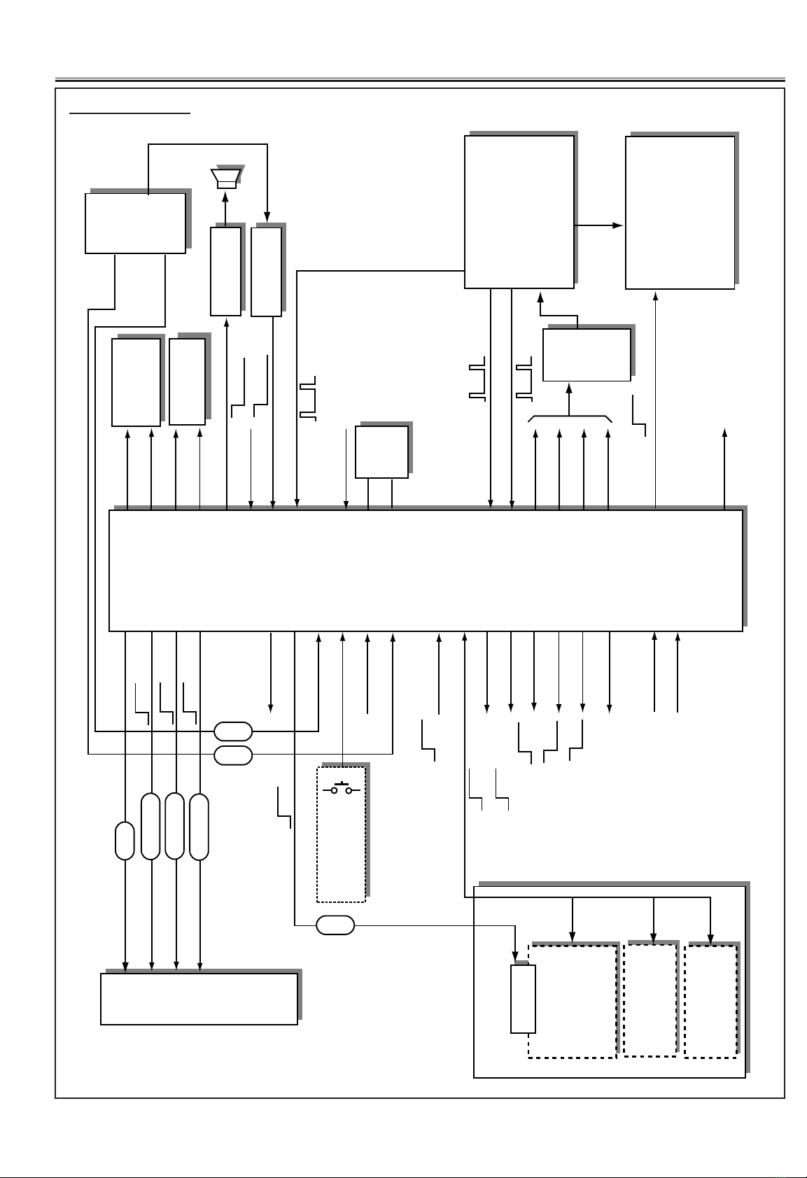
-10- Service Manual EH1 chassis
Adjust. items Initial value Status Description
+000 K1 +000 ADJSTBL Signal level adjustment for A2 stereo, 500mVrms at 54% dev. on pin 1 of SCART 1
+001 K2 -006 ADJSTBL Separation adjustment for A2 stereo, minimise R signal on pin 3 of SCART 1
+002 STID +000 Fixed Judgement algolizum for A2 stereo, 0: FAST 1:NORMAL 2:FAST -> NORMAL
+003 ATT +004 Fixed Sound level adjustment between A2 stereo and NICAM stereo decoded output
+004 VFreq +130 Fixed Not used
+005 VCent +086 ADJSTBL Vertical centre adjustment for 50Hz
+006 VSize +028 ADJSTBL Vertical size adjustment for 50Hz
+007 SCore +010 RECOMD Vertical linearity adjustment (centre, top/bottom part), common data of 50/60Hz
+008 VLner +009 RECOMD Vertical linearity adjustment (top and bottom part), common data of 50/60Hz
+009 HCent +175 ADJSTBL Horizontal centre adjustment for 50Hz
+010 HSize +032 ADJSTBL Horizontal width adjustment for 50Hz
+011 PinAmp +023 RECOMD Horizontal pincushion adjustment for 50Hz
+012 Tilt +022 RECOMD Trapezoid distortion correction adjustment for 50Hz
+013 UCoPin +010 RECOMD Upper corner pincushion adjustment, common data of 50/60Hz
+014 LCoPin +010 RECOMD Lower corner pincushion adjustment, common data of 50/60Hz
+015 VBow +011 RECOMD Vertical line correction adjustment, common data of 50/60Hz
+016 VAngle +007 RECOMD Parallelogram distortion correction adjustment for 50Hz
+017 HVCmpV +007 Fixed Vertical size correction due to beam current, common data of 50Hz/60Hz
+018 HVCmpH +007 Fixed Horizontal width correction due to beam current, common data of 50/60Hz
+019 VFreq60 +000 Fixed Setting of vertical osc. frequency for 60Hz (Not used)
+020 VCent60 -002 Fixed Vertical centre adjustment for 60Hz (difference to ITEM 5)
+021 VC16950 +000 Fixed Vertical centre adjustment on 16:9 mode for 50Hz (difference to ITEM 5)+00
+022 VC16960 +000 Fixed Vertical centre adjustment on 16:9 mode for 60Hz (difference to ITEM 5)
+023 VSize60 +000 Fixed Vertical size adjustment for 60Hz (difference to ITEM 6)
+024 VS16950 +000 Fixed Vertical size adjustment on 16:9 mode for 50Hz (difference to ITEM 6)
+025 HCent60 +003 Fixed Horizontal centre adjustment for 60Hz (difference to ITEM 9)
+026 HCentTX -010 Fixed Horizontal centre adjustment on teletext mode (difference to ITEM 9)
+027 HSize60 +002 Fixed Horizontal width adjustment for 60Hz (difference to ITEM 10)
+028 PinAmp60 +001 Fixed Horizontal pincushion adjustment for 60Hz (difference to ITEM11)
+029 Tilt60 +003 Fixed Trapezoid distortion correction for 60Hz (difference to ITEM12)
+030 Colour +023 Fixed Sub colour setting
+031 TintAN +069 Fixed Tint setting for AN5390
+032 Cont +027 Fixed Sub contrast setting
+033 Bright +022 Fixed Sub brightness setting
+034 DriveR +152 ADJSTBL R-drive adjustment of white-balance
+035 DriveB +160 ADJSTBL B-drive adjustment of white-balance
+036 CutofG +050 RECOMD G-cut off adjustment of white-balance
+037 CutofR +063 RECOMD R-cut off adjustment of white-balance
+038 CutofB +042 RECOMD B-cut off adjustment of white-balance
+039 BYGinPA +035 Fixed B-Y gain setting (PAL)
+040 RYAnglPA +000 Fixed R-Y angle setting (PAL)
+041 MatrxPA +003 Fixed G-Y matrix ratio setting (PAL)
+042 BYGinNT +037 Fixed B-Y gain setting (NTSC)
+043 RYAnglNT +000 Fixed R-Y angle setting (NTSC)
+044 MatrxNT +002 Fixed G-Y matrix ratio setting (NTSC)
+045 BYGinSE +037 Fixed B-Y gain setting (SECAM)
+046 RYAnglSE +000 Fixed R-Y angle setting (SECAM)
+047 MatrxSE +002 Fixed G-Y matrix ratio setting (SECAM)
+048 TintSW +009 Fixed Tint setting for AN5390
+049 ABLACL* +000 Fixed ABL/ACL defeat switch and other setting
+050 Black +104 Fixed Setting of operational point and gain for black expansion function
+051 Gamma +240 Fixed Setting of gamma compensation (o: minimum, 240: maximum)
+052 White +032 Fixed Setting of slice level for white peak and adder value to B signal
+053 ABL +095 Fixed Setting of ABL operational point and gain
+054 ACL +207 Fixed Setting of ACL operational point and gain
+055 VMGain +012 Fixed Gain setting of VM
+056 SW12 +000 Fixed Y/C delay value setting for AN5390
+057 DCSGain +220 ADJSTBL Gain setting of DSC
+058 Sharp +004 Fixed Sub sharpness adjustment
+059 DGain +120 Fixed Sharpness setting of small signal part
+060 DCore +125 Fixed Coring setting of Dgain
+061 DCoreSNR +000 Fixed Change Dcore value according to TDA9143 noise detection (0: No correction)
+062 Sepetn +100 Fixed Setting of Dgain and aperture control value
Adjustment Items and data Table

-11-
Service Manual EH1 chassis
+063 Xtal +002 Fixed X’tal setting, 0:3.58+3.58, 1:3.58, 2:4.43, 3:4.43+3.58
+064 System +224 Fixed Sub address setting 01 of TDA9134
+065 TintTDA +016 Fixed Tint setting of TDA9143
+066 YDelyPA +010 Fixed Y/C phase setting for PAL (sub address setting 18 of TDA9143)
+067 YDelyNT +010 Fixed Y/C phase setting for NTSC (sub address setting 18 of TDA9143)
+068 YDelySE +010 Fixed Y/C phase setting for SECAM (sub address setting 18 of TDA9143)
+069 Country +001 ADJSTBL 0: auto search 1: ATS
+070 WideOpt +001 Fixed 0: 16:9 mode off 1: 16:9 mode on
+071 TxBrit +040 Fixed Black level setting of teletext mode
+072 TxCont +062 Fixed Contrast setting of teletext
Notes:
+ The initial value that the CPU writes down the CPU ROM data to the memory when replaced the memory IC. TV
set does not operate correctly with this initial value.
+ The items which are shown with “fixed” in the status column in the table above are preset by factory as standard.
So do not change value otherwise the set may not operate properly.
+ The items which are shown with “RECOMD” are normally not required for re-adjustment but it may change the
value to improve the performance.
+ The items which are shown with “ADJSTBL” should be re-adjusted following steps.
STEREO SEPARATION ADJUSTMENT
1. Enter to the service mode.
2. Select item 000 and set data to “+000“, select item 001
and set data to “-006“.
VERTICAL CENTRING ADJUSTMENT
1. Receive circular pattern.
2. Enter to the service mode.
3. Select Item 5 and adjust the vertical centre.
VERTICAL HEIGHT ADJUSTMENT
1. Receive circular pattern.
2. Enter to the service mode.
3. Select Item 6 and adjust the vertical height.
HORIZONTAL CENTRING ADJUSTMENT
1. Receive circular pattern.
2. Enter to the service mode.
3. Select Item 9 and adjust the horizontal centre.
HORIZONTAL WIDTH ADJUSTMENT
1. Receive circular pattern.
2. Enter to the service mode.
3. Select Item 10 and adjust the horizontal width.
WHITE BALANCE ADJUSTMENT
1. Receive white pattern.
2. Enter to the service mode.
3. Adjust white balance using the following items,
Item 034 R drive adjustment
Item 035 B drive adjustment
DCS GAIN ADJUSTMENT
1. Enter to the service mode.
2. Select item 059 and set data to “100”.
AUTO SETUP OPTION SETTING
1. Enter to the service mode.
2. Select item 057 and set data as follows;
Value +000 : Auto search mode for UK and Ireland
Value +001 : ATS mode for W. Europe countries.
SERVICE ADJUSTMENTS-1
After replacing the memory IC, IC802, following service adjustments must be carried out.

-12- Service Manual EH1 chassis
VCO ADJUSTMENT
1. Receive the circular pattern.
2. Adjust the picture to obtain the best picture by using
T103.
B1 POWER SUPPLY ADJUSTMENT
1. Set VR641 to be mechanical centre before pressing
the main switch.
2. Receive the circular pattern.
3. Set brightness and contrast controls to normal.
4. Connect digital V-meter to “TP453” on the sub/def.
board.
5. Adjust voltage to be 137±0.5VDC by using VR641 on
the sub/def. board.
AFT ADJUSTMENT
1. Receive the clearest station.
2. Adjust AFT to obtain the best picture by using T102.
AGC ADJUSTMENT
NOTE:
Do not attempt this adjustment with weak
signal.
1. Receive the clearest station.
2. Set AGC VR(VR101) in direction which causes snow
noise to appear, then in the opposite direction until
snow noise just disappears.
FM DETECTOR ADJUSTMENT(UK/Ireland only)
1. Receive the monaural station of system I.
2. Connect voltmetre between TPC and TPE.
3. Adjust the voltage to be 6.0±0.2VDC by using T101.
PILOT ADJUSTMENT(Europe only)
1. Receive the A2 stereo signal
Carrier :5.5MHz + 5.74MHz
Deviation :27kHz
2. Connect oscilloscope between TP34A(pin 5 of IC3401)
and TP34E.
3. Adjust the amplitude to be maximum by using T3401.
VIDEO AMPLITUDE ADJUSTMENT(Europe only)
1. Receive the PAL colour bar pattern.
2. Connect oscilloscope between JT1201(+) and
JT1201E(-) on the back board.
3. Adjust the video amplitude to be 1.0Vp-p±0.05V by
using VR1201 on the back board.
DOUBLE SCAN ADJUSTMENT
Receive the PAL colour bar pattern. Adjustment points
are on the double scan board.
[PLL ADJUSTMENT]
1. Connect oscilloscope between C7226-(TPOSC)(+)
and GND(-).
2. Adjust voltage to be 2.5VDC by using T7201.
[CLAMP ADJUSTMENT]
1. Connect voltmetre between pin 52 of IC7201(+) and
pin 48 of IC7201(-).
2. Adjust voltage to be 2.0VDC by using VR7201.
[OUTPUT LEVEL ADJUSTMENT-Y]
1. Connect oscilloscope between pin 6 of K73C(+) and
GND(-).
2. Adjust the Y signal amplitude to be 0.7Vp-p by using
VR7351.
0.7Vp-p
2.5VDC
DC=0
1.0Vp-p
100% white level
SERVICE ADJUSTMENTS-2
Please refer to the “Component Locations” for the adjustments and test points.

-13-
Service Manual EH1 chassis
[OUTPUT LEVEL ADJUSTMENT-R-Y]
1. Connect oscilloscope between pin 10 of K73C(+) and
GND(-).
2. Adjust the R-Y signal amplitude to be 0.7Vp-p by using
VR7352.
[OUTPUT LEVEL ADJUSTMENT-B-Y]
1. Connect oscilloscope between pin 8 of K73C(+) and
GND(-).
2. Adjust the B-Y signal amplitude to be 0.7Vp-p by using
VR7353.
SCREEN ADJUSTMENT
1. Receive the PAL colour bar pattern.
2. Connect oscilloscope between JTP47G(+) and
JTP47E(-) on the CRT unit.
3. Adjust colour control to minimum, brightness to centre
and contrast to minimum.
4. Adjust the black level to be 165VDC±5V by using
SCREEN VR on the FBT.
HIGH VOLTAGE CONFIRMATION
1. Receive the white pattern.
2. Set brightness and contrast controls to maximum.
3. Connect digital V-meter between “TP451” and
“TP452”, and high voltage meter to CRT anode.
4. Confirm high voltage to be 28.5 ± 1 KV at beam
current 1.8, and less than 32.5 KV at 0 beam current.
FOCUS ADJUSTMENT
By using FOCUS VR, adjust focus control for well
defined scanning lines.
165VDC
DC=0
Black level
0.7Vp-p
0.7Vp-p

-14- Service Manual EH1 chassis
MAIN BOARD (Component side)
A101
IC101
IC204 IC202
IC3451
IC3401 IC3800
IC201
SCAN CONVERTER UNIT
IC205
K2PO K2VI K2PL
K2K K2L
K2W
K2Y
IC3431
IC3531
IC3500
IC801
IC3521
IC674
IC678
TPA
TPE
A101
TPD
VR101
AGC
T101
T102
IC101
T103
IC204 IC202
IC3451
IC3401 IC3800
TP34A
T3401
IC201
IC207
IC673
SCAN CONVERTER UNIT
IC205 IC206
VIDEO UNIT
TP2C
TP2B
TP2A
K2PO K2VI K2PL
K2K K2L
K2W
K2Y
IC677
IC3431
IC3531
IC3500
IC671
IC350
IC802
IC801
IC3521
IC001
IC675 IC676
TPC
TP34E
IC203
AFT
PILOT VCO
AGC
FM
COMPONENT LOCATIONS

-15-
Service Manual EH1 chassis
MAIN BOARD (Circuit side)
A101
Q103
Q102
Q101
Q104
Q114
Q115
Q112
Q111 Q131 Q107
IC101
Q211
Q212
Q213
IC202 IC204
Q214
IC206
IC3451
Q3483 Q3481
Q3412 Q3411 Q3482
IC001 IC3521
Q3431
IC3431
Q3432
IC3531
IC3500
Q873
Q851
IC801
Q804 Q803 Q802
IC3800 IC3401
IC201
IC207
IC205
Q835
Q836 Q831
Q832
Q833
Q3484

-16- Service Manual EH1 chassis
IC652 VR641
Q641
Q661
Q664
D615
Q611
Q612
Q613
T611
Converter trans.
T403
Choke trans.
T402
Flyback trans.
IC653
Q422
Q474
IC501
Vertical
output
Q572
Q555
Q554
Q556
Q461
Q473 Q472
Q471
Q401
Horizontal output
Q431
IC431
Q402
LIVE SIDE
+B VOLT
TP4E
TP453
TP452 TP451
SCREEN
POWER DEF BOARD (Component side)

-17-
Service Manual EH1 chassis
K23N K23M
J23HW
H-SIZE
SW
IC2331
IC361
VR391
H-OSC
Q2314
Q2312
IC2201
IC2101
IC2203 IC2102
IC2206
IC2204
IC2202
IC2205
Q2207
Q2206
Q2204
Q2205
Q1751
Q2202 Q1752
Q1753
Q1755
Q2105
Q2106
Q2110
Q2109
Q2108 Q2107
Q2161
Q2102 Q2101
Q2103
Q2104
Q2201
K20PL K20VI K20PO
SUB DEF BOARD (Component side)
VIDEO BOARD (Component side)
IC2351
IC2341
IC2311
IC2371 IC2391
IC2381
IC2361
Q2341
Q364
Q2313
Q361
Q2311
SUB DEF BOARD (Circuit side)

-18- Service Manual EH1 chassis
IC7203
IC7204
IC7201
VR7201
REF TOP
Q7304 Q7338
Q7308
Q7301
Q7307
Q7306
Q7359 Q7355 Q7351
IC7223
IC7206
IC7222
IC2101
Q7360
Q7362 Q7361
VR7353
Q7356
Q7358Q7357
VR7352
Q7352
Q7354Q7353
VR7351
IC7215
IC7212
IC7207
IC7214
IC7301
K73AK73CK73B
T7201
CLAMP
PLL
R-Y
B-Y
Y
DOUBLE SCAN BOARD (Component side)
IC7211
IC7208
IC7205 IC7209 Q7201 IC7202
DOUBLE SCAN BOARD (Circuit side)

-19-
Service Manual EH1 chassis
K1001
K1002
K1003
VR1201
Video Level
Q1231 Q1232
Q1002 Q1205
Q1206 Q1203
Q1204 Q1202
Q1208
Q1201
Q1207
IC1201
Q1001
K10Y K10W
JT1201
JT1201E
VIDEO AMP
Q702
Q703
Q721
Q701
Q731
Q711
IC711
B-OUT
IC721
G-OUT IC731
R-OUT
K701
JTP47E
JTP47G
BACK BOARD (Component side)
CRT BOARD (Component side)

-20- Service Manual EH1 chassis
T602 T681
SW601
Mains SWitch
F601
Fuse
A1901 SW1901 SW1902 SW1903 SW1904
Prog+ Prog- Vol+ Vol- F/M PT SYS
T602 T681
SW1905 SW1906 SW1907
Q682
Q688
Q1111
Q1121 Q1131
K1101 K001
FRONT BOARD (Component side)
Table of contents
Other Sanyo TV manuals

Sanyo
Sanyo CE14SP4R User manual

Sanyo
Sanyo CE15LC4-B User manual

Sanyo
Sanyo C21PM86Z User manual

Sanyo
Sanyo CE21BN4-C User manual

Sanyo
Sanyo CPP3024W User manual

Sanyo
Sanyo EP58B Installer manual

Sanyo
Sanyo CP29KX2Z User manual

Sanyo
Sanyo CE-25D3-C User manual

Sanyo
Sanyo CE29FFV1-F User manual

Sanyo
Sanyo HT30547 User manual

Sanyo
Sanyo CE27LD4-B User manual

Sanyo
Sanyo DP50741 User manual

Sanyo
Sanyo DS31520 User manual

Sanyo
Sanyo CZP331 OTX User manual

Sanyo
Sanyo CE24WN5-B User manual

Sanyo
Sanyo CP28WF1 User manual

Sanyo
Sanyo C14EA80D User manual

Sanyo
Sanyo 28DN2F User manual

Sanyo
Sanyo CR14SR8-00 User manual

Sanyo
Sanyo C21EF27 User manual