Service Adjustments
L
?
.
L
L
.
.
L
SAFETY PRECAUTIONS :An isolation transformer should be connected in the power line between the receiver and the AC
line before any service is performed on the receiver.
X-RADIATION PRECAUTION The primary source of X-RADIATION in television receiver is the picture tube, The picture
tube is specially constructed to limit X-RADIATION emission. For continued X-RADIATION protection, the replacement tube must
be the same type as the original including suffix letter, Excessive high voltage may produce potentially hazardous X-RADIATION.
To avoid such hazards, the high voltage must be maintain within specified limit. Refer to this service manual for specific high
voltage limits. If high voltage exceeds specified limits, take necessary corrective action. Carefully follow the instructions for +B1 volt
power supply adjustment, and high voltage check to maintain the high voltage within the specified limits.
NOTE; Do not attempt this adjustment with weak signal.
(1) Tune the receiver to most clearest (or strongest) VHF
station in your area. Set the brightness and contrast
controls to maximum. Set the colour control to minimum.
(2) Set AGC(VR191 )control to mid- range.
(3) Turn AGC control in direction which causes snow to appear,
then in the opposite direction until the snow just disappears.
(1) Connect DC meter to R638 (R637 side) and the ground.
Set the +B -adjustment control (VR631 )to mid- range.
(2) Set the brightness and contrast to minimum.
Tune the receiver to an active channel and synchronized
picture.
(3) Adjust +B -adjustment control(VR631 )for 130 *0.5 volt
DC.
(1) Receive the monochrome circular pattern.
(2) Set the brightness and contrast to normal.
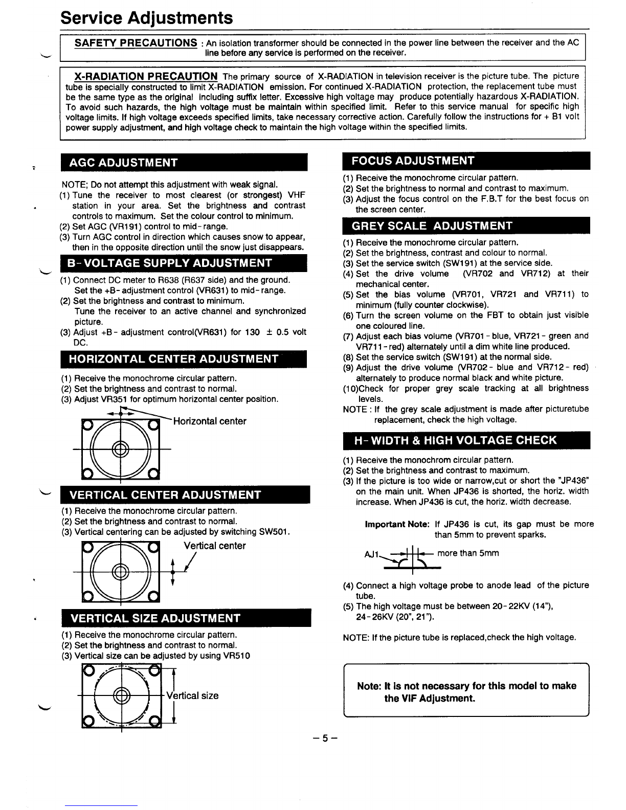
(3) Adjust VR351 for optimum horizontal center position.
.Horizontal center
11
(1) Receive the monochrome circular pattern.
(2) Set the brightness and contrast to normal.
(3) Vertical centering can be adjusted by switching SW501.
Vertical center
+!
(1) Receive the monochrome circular pattern.
(2) Set the brightness and contrast to normal.
(3) Vertical size can be adjusted by using VR51 O
rtical size
(1) Receive the monochrome circular pattern.
(2) Set the brightness to normal and contrast to maximum.
(3) Adjust the focus control on the F,B.T for the best focus on
the screen center.
(1) Receive the monochrome circular pattern.
(2) Set the brightness, contrast and colour to normal.
(3) Set the service switch (SW191 )at the service side.
(4) Set the drive volume (VR702 and VR712) at their
mechanical center.
(5) Set the bias volume (VR701, VR721 and VR711 )to
minimum (fully counter clockwise).
(6) Turn the screen volume on the FBT to obtain just visible
one coloured line.
(7) Adjust each bias volume (VR701 -blue, VR721 -green and
VR711 -red) alternately until adim white line produced.
(8) Set the service switch (SW191 )at the normal side.
(9) Adjust the drive volume (VR702 -blue and VR712 -red)
alternately to produce normal black and white picture.
(1 O)Check for proper grey scale tracking at all brightness
levels.
NOTE: If the grey scale adjustment is made after picturetube
replacement, check the high voltage.
(1) Receive the monochrom circular pattern.
(2) Set the brightness and contrast to maximum.
(3) If the picture is too wide or narrow, cut or short the “JP436
on the main unit, When JP436 is shorted, the horiz. width
increase. When JP436 is cut, the horiz. width decrease.
Important Note: If JP436 is cut, its gap must be more
than 5mm to prevent sparks.
“=&0rethan5mm
(4) Connect ahigh voltage probe to anode lead of the picture
tube.
(5) The high voltage must be between 20-22KV(14“),
24- 26KV (20”, 21 “).
NOTE: If the picture tube is replaced, check the high voltage.
Note: It is not necessary for this modei to make
the ViF Adjustment.
<J
–5–