MISCELLANEOUS ADJUSTMENTS SET 4737 PSET 4737 P
SET 4737 PSET 4737 P
SET 4737 Paa
aa
agg
gg
ge 1e 1
e 1e 1
e 1
B+ CHECKB+ CHECK
B+ CHECKB+ CHECK
B+ CHECK
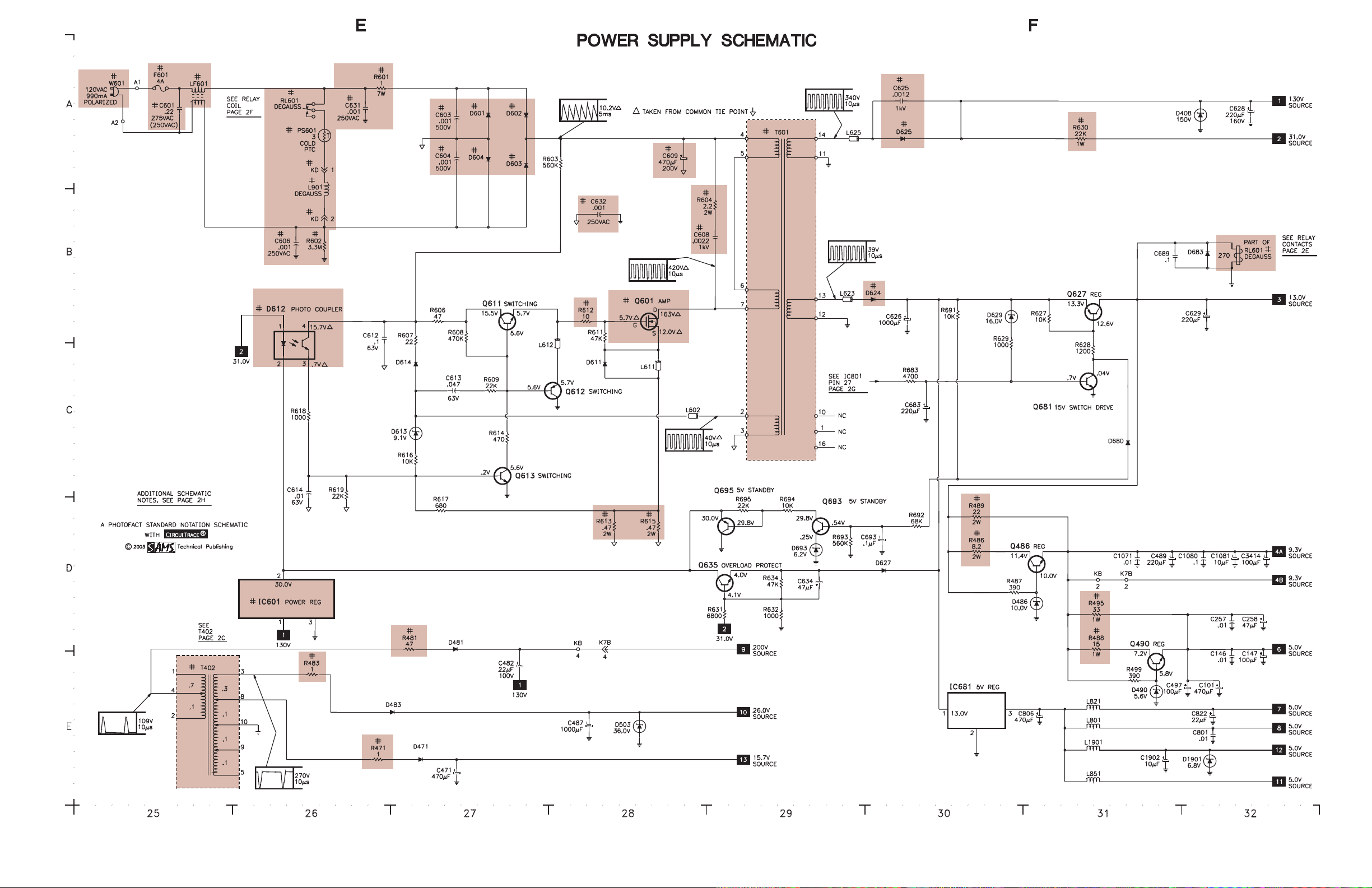
Connect a digital DC voltmeter to the cathode of D625. Set brightness and picture
to minimum. With AC line set to 120VAC, B+ should read 130V ±2.0V.
HIGHHIGH
HIGHHIGH
HIGHVV
VV
VOLOL
OLOL
OLTT
TT
TAA
AA
AGE CHECKGE CHECK
GE CHECKGE CHECK
GE CHECK
Tune in a picture. Set customer controls to minimum. Connect a high voltage probe
to CRT anode. High voltage should measure 26kV to 28kV.
ENTERING SERENTERING SER
ENTERING SERENTERING SER
ENTERING SERVICE MODEVICE MODE
VICE MODEVICE MODE
VICE MODE
Disconnect the AC power cord. While pressing the menu button on the front of the
set, connect the AC power cord. Use the channel up and down buttons to select the
service number. Use volume up and down buttons to change the value. Press the
menu button to exit the service mode.
HORIZONTHORIZONT
HORIZONTHORIZONT
HORIZONTALAL
ALAL
ALWIDTHWIDTH
WIDTHWIDTH
WIDTH
Tune in a crosshatch pattern. Enter the service mode and select service item number
47 EWD. Adjust for the proper horizontal width.
HORIZONTHORIZONT
HORIZONTHORIZONT
HORIZONTAL POSITIONAL POSITION
AL POSITIONAL POSITION
AL POSITION
Tune in a crosshatch pattern. Enter the service mode and select service item number
03 HP. Adjust for the best horizontal centering.
RF ARF A
RF ARF A
RF AGC DELAGC DELA
GC DELAGC DELA
GC DELAYY
YY
Y
Tune in a picture. Enter the service mode and select service number 42 RAD.
Adjust where no snow (noise) appears in picture.
VERVER
VERVER
VERTICAL SIZETICAL SIZE
TICAL SIZETICAL SIZE
TICAL SIZE
Tune in a crosshatch pattern. Enter the service mode and select service item number
04 VS. Adjust for proper vertical size and best vertical linearity.
VERVER
VERVER
VERTICAL CENTERINGTICAL CENTERING
TICAL CENTERINGTICAL CENTERING
TICAL CENTERING
Tune in a crosshatch pattern. Check that the pattern is centered. If too low, replace
resistor R513 1000 ohms 1/2W with a 470 ohms 1W. If too high, remove resistor
R513 1000 ohms 1/2W.
VCOVCO
VCOVCO
VCO
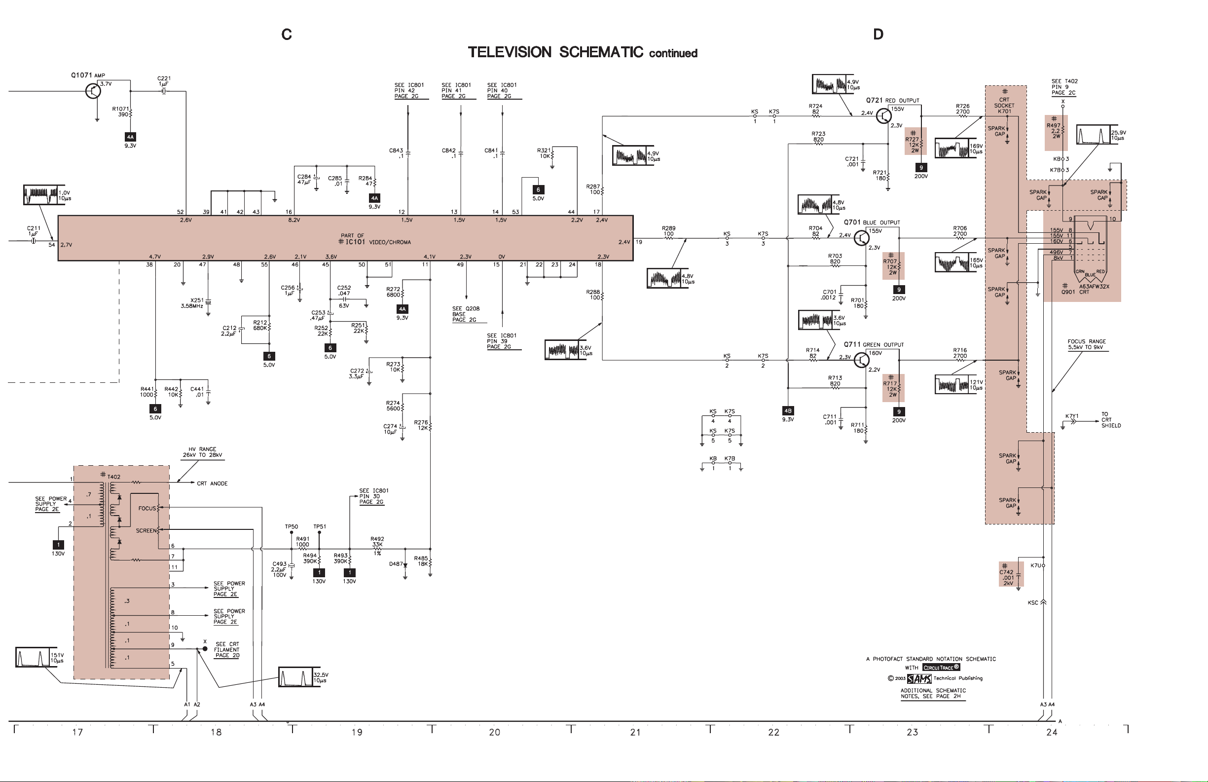
VCO must be adjusted after IC101, IC802, or T151 is replaced. Tune in a picture.
Connect positive lead of a digital voltmeter to pin 58 of IC101 and the negative lead
to TE7. Adjust T151 to obtain a reading of 3.6V ± 0.2V.
VIDEO LEVELVIDEO LEVEL
VIDEO LEVELVIDEO LEVEL
VIDEO LEVEL
Tune in a color bar pattern. Set picture and brightness to normal. Connect an
oscilloscope to the emitter of Q202, and the negative lead to ground. Enter the
service mode and select service number 46 VL. Adjust for 1.0Vp-p ±0.1Vp-p
waveform on the oscilloscope.
GRAGRA
GRAGRA
GRAY SCALEY SCALE
Y SCALEY SCALE
Y SCALE
Tune in an active channel. Enter the service mode. Set the value of service numbers
15 RB, 16 GB, and 17 BB to 0. Set the value of service numbers 18 RD and 20 BD
to 55. Set screen control, color, brightness, and picture to minimum. Adjust screen
control, if necessary, to obtain a barely visible horizontal line. Select service
number 73. Adjust the bias levels for a white line. Select service number 72 DRV
and adjust the drive values for normal black and white picture at all brightness
levels.
SUB BRIGHTNESSSUB BRIGHTNESS
SUB BRIGHTNESSSUB BRIGHTNESS
SUB BRIGHTNESS
Tune in a color bar pattern. Set picture and brightness to normal. Connect positive
lead of a digital voltmeter to TP51 and the negative lead to TP50. Enter the service
mode and select service number 53 SB. Adjust for 820mV ±10mV.
SUB COLOR,SUB COLOR,
SUB COLOR,SUB COLOR,
SUB COLOR, SUBSUB
SUBSUB
SUBTINTTINT
TINTTINT
TINT,,,,
,SUB SHARPNESSSUB SHARPNESS
SUB SHARPNESSSUB SHARPNESS
SUB SHARPNESS
Tune in a picture. Enter the service mode. Select service number 54 SCO. Adjust for
normal color level. Select service number 55 STI. Adjust for normal flesh tones.
Select service number 56 SSH. Adjust for contrast range.
OSD HORIZONTOSD HORIZONT
OSD HORIZONTOSD HORIZONT
OSD HORIZONTAL POSITIONAL POSITION
AL POSITIONAL POSITION
AL POSITION
Tune in a local channel. Enter the service mode and select service item number 59
HR. Adjust for centered on screen menu.
SOUNDSOUND
SOUNDSOUND
SOUND
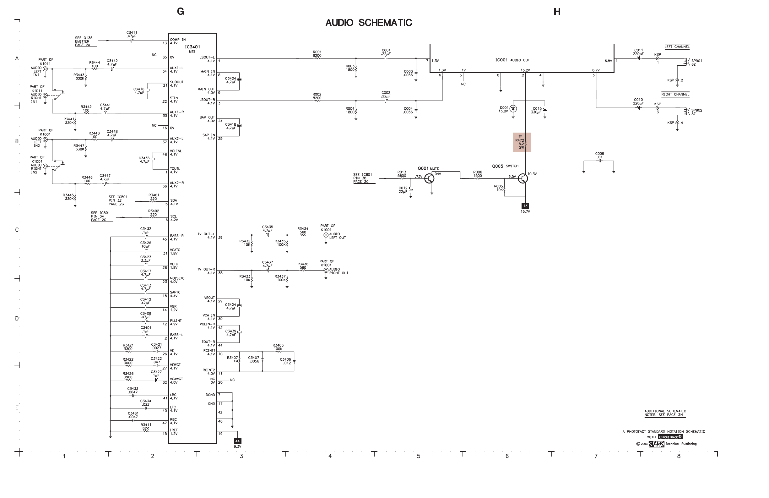
Tune in a local channel. Connect an oscilloscope to the base of Q135, and the
negative lead to ground. Enter the service mode and select service number 45 FL.
Adjust for 0.693Vp-p ± 0.07Vp-p waveform on the oscilloscope
INPUT LEVELINPUT LEVEL
INPUT LEVELINPUT LEVEL
INPUT LEVEL
Set generator to 1kHz audio frequency and L-R modulating signal. Connect an
oscilloscope to pin 38 of IC3401. Enter service mode and select the service item
number 60 ATT. Adjust for 0.7Vp-p waveform.
SEPSEP
SEPSEP
SEPARAARA
ARAARA
ARATIONTION
TIONTION
TION
Set generator to pilot, 300Hz audio frequency, and left modulating signal. Connect
an oscilloscope to pin 38 of IC3401 and ground. Enter the service mode and select
service number 61 WDB. Adjust for minimum amplitude of the waveform. Set
generator to 8kHz audio frequency. Select service number 62 SPC and adjust for
minimum amplitude of the waveform.
PURITYPURITY
PURITYPURITY
PURITY
NOTE: Operate the receiver for 15 minutes to allow warm-up of CRT.
Use a degaussing coil to demagnetize the CRT. Tune in a green raster. Loosen the
clamp screw. Slide deflection yoke back as far as possible. Adjust purity tabs to
center the vertical green band. Slide the deflection yoke forward to produce a
uniform green screen. Tighten the clamp screw.
CONVERGENCECONVERGENCE
CONVERGENCECONVERGENCE
CONVERGENCE
Tune in a dot pattern. Loosen the clamp screw. Adjust the 4 pole magnets to
converge the red and blue dots at the center of the screen. Adjust the 6 pole magnets
to converge the red/blue dots over the green dots at the center of the screen.
NOTE: Rotate the two tabs of each set of magnets equally and opposite to converge
vertically and rotate both tabs in the same direction to converge horizontally. The 4
and 6 pole magnets interact, repeat adjustment until center convergence is correct.
Tune in a crosshatch pattern. Remove the tilt adjustment wedges between deflection
yoke and the CRT. Loosen the clamp screw. Tilt the deflection yoke up or down to
converge the vertical lines at the top and bottom of the screen and the horizontal
lines at the right and left sides of the screen. Tilt the deflection yoke to the right or
left to converge the horizontal line at the top and bottom of the screen and the
vertical line at the right and left sides of the screen. Repeat convergence procedure
if necessary to obtain best overall convergence. Replace the tilt adjustment wedges.
Tighten the clamp screw.
CRCR
CRCR
CRT NECK ASSEMBLT NECK ASSEMBL
T NECK ASSEMBLT NECK ASSEMBL
T NECK ASSEMBLYY
YY
Y
IC802 REPLAIC802 REPLA
IC802 REPLAIC802 REPLA
IC802 REPLACEMENTCEMENT
CEMENTCEMENT
CEMENT
Perform the following adjustments after replacing IC802. Enter the service mode,
select service number 03 HP and set value to 14. Select service number 07 VLN and
set value to 13. Select service number 28 PRE and set value to 3. Select service
number 37 AF and set value to 1. Select service number 57 OPT and set value to
100. Select service number 58 OP2 and set value to 32. Press the menu button to
exit service mode.
SerSer
SerSer
Servicevice
vicevice
vice VV
VV
Valuealue
aluealue
alue Initial RefInitial Ref
Initial RefInitial Ref
Initial Ref Initial SetInitial Set
Initial SetInitial Set
Initial Set On-SetOn-Set
On-SetOn-Set
On-Set
No.No.
No.No.
No. AdjustmentAdjustment
AdjustmentAdjustment
Adjustment RangRang
RangRang
Rangee
ee
eVV
VV
Valuealue
aluealue
alue UpUp
UpUp
Up VV
VV
Valuealue
aluealue
alue VV
VV
Valuealue
aluealue
alue NotesNotes
NotesNotes
Notes
01 HFR 0 - 63 29 29 29 Horizontal Frequency
02 AFC 0, 1 0 0 0 AFC Gain
03 HP 0 - 31 15 14 14 H-Position (H-Centering)
04 VS 0 - 127 64 64 51 Vertical Size
05 VPO 0 - 63 5 5 5 Vertical Position
06 VSP 0, 1 0 0 0 Vertical Set Up
07 VLN 0 - 31 18 13 13 Vertical Linearity
08 CRS 0 - 3 0 0 0 Cross B/W
09 GRY 0, 1 1 1 1 Gray Mode
10 VSC 0 - 31 8 8 8 Vertical S Correction
11 HBR 0 - 7 3 3 3 H BLK R
12 HBL 0 - 7 4 4 4 H BLK L
13 CDM 0, 1 0 0 0 CD Mode
14 VC 0 - 7 7 7 7 Vertical Compression
15 RB 0 - 255 0 0 0 Red Bias
16 GB 0 - 255 0 0 0 Green Bias
17 BB 0 - 255 0 0 7 Blue Bias
18 RD 0 - 127 64 64 85 Red Drive
19 GD 0 - 15 8 8 8 Green Drive
20 BD 0 - 127 64 64 62 Blue Drive
21 SBI 0 - 127 48 48 48 Sub Bias
22 OSD 0 - 3 3 3 3 OSD Contrast
23 POS 0, 1 0 0 0 Pre/Over/SW
24 FLS 0 - 7 1 1 1 Filter System
25 CKO 0 - 7 3 3 3 Color Killer Operation
26 GYA 0, 1 0 0 0 G-Y Angle
27 CRG 0 - 3 2 2 2 Coring Gain
28 PRE 0 - 3 1 3 3 Pre Shoot Adjust
29 WP 0, 1 0 1 1 White Peak Limiter, 0 = On, 1 = Off
30 FSW 0, 1 0 0 0 FBP Blanking Switch
31 VBL 0, 1 0 0 0 Vertical Blanking Switch
32 BSG 0 - 3 2 2 2 Black Stretch Gain
33 BSS 0 - 3 1 1 1 Black Stretch Start
34 DCR 0 - 3 1 1 1 DC Reset
35 YGM 0 - 3 1 1 1 Y Gamma
36 CBP 0, 1 0 0 0 C Bypass
37 AF 0, 1 0 1 1 Auto Flesh, 0 = Off, 1 = On
38 BAT 0 - 7 4 4 4 Bright ABL Threshold
39 MSD 0, 1 0 0 0 Mid Stop Def
40 ABL 0, 1 0 0 0 ABL Defeat, 0 = On, 1 = Off
41 RYA 0 - 15 2 2 2 R-Y/B-Y Angle
42 RAD 0 - 63 15 15 37 RF AGC Delay
43 IAS 0, 1 0 0 0 IF AGC Switch, 0 = TV (Normal), 1 = AV (IF Gain Minimum)
44 FMM 0, 1 0 0 0 FM Mute
45 FL 0 - 31 15 15 10 FM Level
46 VL 0 - 7 4 4 5 Video Level
47 EWD 0 - 63 39 39 39 EW DC
48 EWA 0 - 63 30 30 30 EW Amp
49 EWT 0 - 63 34 34 34 EW Tilt
50 EWP 0 - 7 7 7 7 EW Corner Top
51 EWB - 8 8 8 EW Corner Bottom
52 HSC - 7 7 7 Horiz Size Comp
53 SB 0 - 63 32 32 31 Sub Brightness
54 SCO 0 - 31 7 7 7 Sub Color
55 STI 0 - 31 20 20 20 Sub Tint
56 SSH 0 - 15 12 12 12 Sub Sharpness
57 OPT 0 - 255 0 100 100 Option, data 1 should be set to 100, in binary 8 bit 01100100
58 OP2 0 - 255 0 32 32 Option, data 2 should be set to 32, in binary 8 bit 0 0100000
59 HR 0 - 63 27 27 27 OSD Horizontal Position
60 ATT 0 - 15 10 7 8 Attenuation
61 WDB 0 - 63 32 32 34 Wide Band
62 SPC 0 - 63 32 32 11 Spectral
63 SBO 0 - 255 5 5 5 Sub Bright Offset
64 PCO 0 - 63 40 40 40 PIP Color
65 PTI 0 - 63 40 40 40 PIP Tint
66 PUV 0 - 63 24 24 24 PIP Top Position
67 PDV 0 - 255 147 147 147 PIP Bottom Position
68 PLH 0 - 63 10 10 10 PIP Left Position
69 PRH 0 - 255 101 101 101 PIP Right Position
70 PCN 0 - 63 42 42 52 PIP Y Level
71 PBS 0 - 63 15 15 15 PIP BGP Phase
72 DRV 0 - 127 64 64 R 85 Red Drive, press 1 to decrease value and 3 to increase value.
DRV 0 - 127 64 64 B 62 Blue Drive, press 7 to decrease value and 9 to increase value.
73 - 0 - 255 0 0 0 Red Bias, press 1 to decrease value and 3 to increase value.
- 0 - 255 0 0 0 Green Bias, press 4 to decrease value and 6 to increase value.
- 0 - 255 0 0 0 Blue Bias, press 7 to decrease value and 9 to increase value.
74 R00
Thru Thru
146 R72 0 - 255 - 0 0 -
SERVICE MODE ADJUSTMENT CHART


 User manual")