User Manual & Datasheet V 1.0
8 Installation Guidelines
While installing the instrument, please take care of the
following points:
1. The instrument should be installed in horizontal or ver-
tical position only.
2. Observe that when installed directly under the mate-
rial inlet source, a canopy called baffle of appropriate
strength and size should be welded right above the in-
strument as shown.
Material Inlet Source
Baffle
Figure 3: Vital -T with Baffle
3. To prevent the ingress of moisture and water seepage
in side mounting position, the cable entries should al-
ways point downwards.
Figure 4: Cable Gland Arrangement
4. Secure the cover of housing tightly. Tighten the cable
glands.
5. Make all electrical connections as instructed in the
manual. Don’t power on the device before verifying
the connections.
6. Weatherproofness of enclosure is guaranteed only if
the cover is in place glands adequately tightened.
Damage due to accidental entry of water can be
avoided if the instrument is installed in a rain shade.
7. If the ambient temperature is high, the instrument
should not be installed to receive direct sunlight. In
case such a position of shade is not available, a heat
shield should be fitted above the instrument especially
if the operating temperature lies between 60◦C and
80◦C.
9 Electrical Connections
Note: is compatible only with 24V DC power supply.
Note: does not have any keys to operate.The Fail-
safe feature has been implemented in accordance
with connection.
9.1 For Fail-safe High
If a device is mounted at top of the tank then follow the
instructions given below for Electrical Connections:
9.2 For Standard Connector
•Connect positive terminal to Pin no. 3 of the device.
•Connect negative terminal to Pin no. 1 of the device.
•Connect fuse between positive terminal and Pin no. 3
of the device.
•Output can be taken between Pin no. 1 and 2.
Figure 5: Fail-safe High
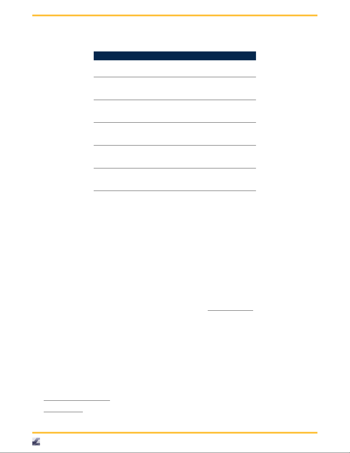
9.3 For M-12 Connector
•Connect positive terminal to Pin no. 1 of the device.
•Connect negative terminal to Pin no. 3 of the device.
•Output can be taken from Pin no. 4.
Figure 6: M-12 Connector Connection for Fail-safe High
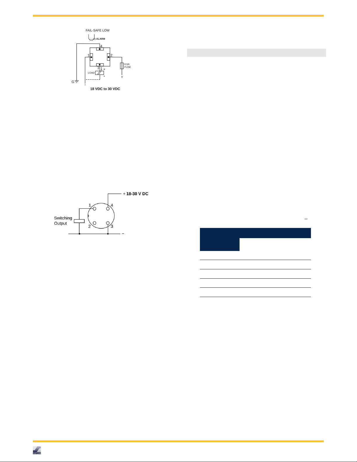
9.4 For Fail-safe Low
If a device is mounted at bottom of the tank then follow
the instructions given below for Electrical Connections:
9.5 For Standard Connector
•Connect positive terminal to Pin no. 2 of the device.
•Connect negative terminal to Pin no. 1 of the device.
•Connect fuse between positive terminal and Pin no. 2
of the device.
Sapcon Instruments Pvt.Ltd.®8