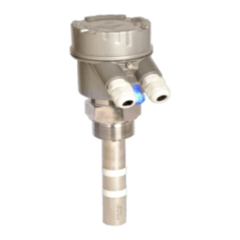
Sapcon SLA Series User manual

SLA-SERIES
Admittance Level Limit Switch
INSTRUCTION MANUAL
Version 2.1

User Manual & Datasheet V 2.1
Contents
RevisionHistory................................................... 3
1Introduction.................................................... 4
2OperatingPrinciple ................................................ 4
3MeasuringSystem................................................. 4
4Features ...................................................... 4
5Applications.................................................... 4
6SystemDescription ................................................ 4
7EvaluationUnit(Standard)............................................ 6
7.1ElectricalSpecifications............................................ 6
7.2MechanicalSpecifications........................................... 6
8ElectronicInsert(ICA-3000A) .......................................... 7
9Probe ....................................................... 7
10InstallationandHandlingGuidelines....................................... 8
11Connection.................................................... 8
12Calibration .................................................... 9
13 Calibration procedure For Fail-Safe High . . . . . . . . . . . . . . . . . . . . . . . . . . . . . . . . . . . . 9
14 Calibration Procedure For Fail-Safe Low . . . . . . . . . . . . . . . . . . . . . . . . . . . . . . . . . . . . 10
15CustomerSupport ................................................ 10
List of Figures
1 SLA ...................................................... 4
2 DescriptionofParts.............................................. 4
3 SystemDiagram................................................ 5
List of Tables
1 ElectricalSpecifications............................................ 6
2 MechanicalSpecifications........................................... 6
3 ElectronicInsert................................................ 7
4 Probe ..................................................... 7
Sapcon Instruments Pvt.Ltd. R
2

User Manual & Datasheet V 2.1
Revision History
Revision Date Author(s) Description
1.0 10 Jan 2014 RND First Version Editing
1.1 20 Sep 2014 MRK Applications Revision
1.2 26 Jun 2015 RND Features Revision
1.3 18 Dec 2015 RND Specs Revision
1.4 19 Jul 2016 RND Specs Revision
2.0 08 Jan 2017 BRND Revised Format
2.1 17 Sep 2017 BRND Branding Revisions
1
1
•Copyright: All content on this document, such as text, graphics, logos and images is the property of Sapcon Instruments Pvt. Ltd.
The selection, arrangement and presentation of all materials on this document and the overall design of this document is the exclusive
property of Sapcon Instruments Pvt. Ltd.
•The images shown in this manual may differ from the actual instrument / housing in terms of dimensions, color and design. Please refer
to GA drawings for dimensional details.
•Values (of performance) described in this manual were obtained under ideal testing conditions. Hence, they may differ under industrial
environment and settings.
General Instructions
•Instrument shouldn’t block the material filling inlet.
•Secure the cover of housing tightly. Tighten the cable glands. For side mounting, the cable glands should point downwards.
•For side mounting, provide a baffle to prevent the material from falling on the probe.
•When handling forks, do not lift them using their tines. While using them with solids, ensure that material size is less than 10mm.
•Deforming the shape of the tines may interfere with the fork’s operating frequency.
•Make all electrical connections as instructed in the manual. Don’t power on the device before verifying the connections.
Sapcon Instruments Pvt.Ltd. R
3

User Manual & Datasheet V 2.1
1 Introduction
SLA is a admittance level limit switch utilizing specially
designed immuno coat probe offers a reliable solution to
level detection problems so far difficult to solve with ca-
pacitance type system utilizing conventional 2 element
probes. It consists of an evaluation unit, an electronic
insert and a probe. The probe is mounted either from
top or side of the vessel. The probe comprises sense and
shield electrodes, electrically isolated from the metallic
tank by the means of a suitable insulator. The two elec-
trodes form an imperfect capacitor with the service ma-
terial acting as the dielectric. Admittance measurement
using immuno coat probe give satisfactory solutions in
tough environments such as where;
•Conductive or non-conductive material coats the
probe.
•There is bridging of material between probe and side
wall.
•Material particles with electrostatic charge and vary-
ing temperature float in the vicinity of the Probe.
Figure 1: SLA
2 Operating Principle
The Sensitive portion of the probe and the container
wall (or ground electrode) from a means to measure
the admittance of the system with and without the
intervening material. When all the parameters that
affect the admittance value are kept constant then its
value changes only due to the difference in material level.
This change after amplification is used to operate a
relay, the output contacts of which are used for signaling
or control.
3 Measuring System
The complete admittance system comprises of the fol-
lowing:
•Probe of special construction immuno coat system.
•Electronic Insert ICA-3000A in plastic housing, fully
potted with epoxy resin.
•Evaluation Unit type LEVTESTER - SLA...Series.
Figure 2: Description of Parts
4 Features
•Ingress Protection of IP67.
•Coating Immunity specially for sticky and viscous
media.
•Universal Supply: 90 - 265V AC and 18V DC.
•Available in Integral as well as remote models.
•Customized mountings and probe lengths.
•Calibration possible from remote location.
5 Applications
•Food Industries & FMCG
•Sugar Industry
•Packaging Industry
•Foundry & Castings
•Soya Industry
•Bulk Material Handling
•Flour and Rice Mills
6 System Description
PROBE: The probe offers special construction with
two concentrically positioned electrodes, that are isolated
from each other and ground (Refer to Figure 2). The
innermost electrode serves as the sense electrode whereas
the next one is shield and the outermost is ground. Due
to the typical geometric configuration of the electrodes
and the maintenance of equi-potential
Sapcon Instruments Pvt.Ltd. R
4

User Manual & Datasheet V 2.1
and equi-phase relation between the sense and shield waveforms a high degree of immunity to probe coating and
build-up achieved. The probe head is of cast aluminium construction and is fitted on the probe extension, away from
heat. It is provided with a suitable mounting arrangement of the screwed or flanged type (as per order).
ELECTRONIC INSERT: The electronic insert can either be directly mounted in probe housing or remotely in-
stalled in a separate housing. The electronic insert comprises of an RF Oscillator, Detector and Coat Immunizing
circuitry all encased in a plastic housing and potted with epoxy resin. Built-in terminals on electronic insert facilitate
interconnections. The Insert is further housed in a cast aluminium housing provided with a suitable entry and houses a
high voltage discharge device (Optional).
EVALUATION UNIT: The evaluation unit consists of a step down transformer, rectifier, voltage regulator, os-
cillator, probe immunizing circuitry, set point adjusting capacitor, relay driving circuitry, fail-safe selection LED Indicator
and Relay. In case of time delay model, a separate timing mode selection switch and pot is provided for delay setting.
The electronics along with interconnecting terminals is assembled on a glass epoxy PCB heavily lacquered for rendering
it immune to moisture, dust and fungus.
The card in turn is mounted in a cast aluminium weather proof housing, stoved enamel painted & provided with 3 nos.
of cable entries. The measuring electrode and shield are connected to a radio frequency source. Due to the geometry of
construction and immuno coat circuitry, RF current does not flow between the measuring electrode and shield. Current
can, however, flow between the shield and mounting (ground) which being out of the measuring circuit does not effect
indication. The only path left for the current to flow through is the admittance path via the material to the vessel wall
(ground). This being the only path of interest, the system gives a reliable indication of level.
Figure 3: System Diagram
Sapcon Instruments Pvt.Ltd. R
5

User Manual & Datasheet V 2.1
7 Evaluation Unit (Standard)
7.1 Electrical Specifications
Please refer to Table 1 for Electrical Specifications.
PARAMETER VALUE
Input Power Supply 18 - 55 V DC and 90 - 265 V AC on same terminal
Output One set / Two sets of potential free c/o contacts
rated at 5 Amps, 230 V AC for non-inductive loads
Switching Indication
•Red LED - Alarm
•Green LED - Normal
•Yellow LED - System Fault
Power Consumption 5 W
Response Time 1 to 3 seconds
Failsafe Mode Max. or Min. (Field Selectable)
Time Delay Setting 1 - 25 sec. (For Covered and Uncovered Both)
Table 1: Electrical Specifications
7.2 Mechanical Specifications
Please refer to Table 2 for Mechanical Specifications.
PARAMETER VALUE
Housing
•RB : Cast Aluminium weather proof powder
coated paint IP-65
•SQP : Cast Aluminium weather proof powder
coated paint IP-65 (Square Probe Mounted)
•FP2A : Cast Aluminium weather & flame proof
powder coated paint suitable for gas group IIA &
IIB as per IS 2148
•SNSR : Pressure Die Cast Aluminium weather
proof IP-66
Electrical Connector 1/2”, 3/4” BSP / NPT
Cable Gland Type Single / Double Compression
Operating Temperature Up to 60◦C
Table 2: Mechanical Specifications
Sapcon Instruments Pvt.Ltd. R
6

User Manual & Datasheet V 2.1
8 Electronic Insert (ICA-3000A)
Please refer to Table 3 for Electronic Insert Specifications.
PARAMETER VALUE
Working Frequency 500 KHz (Approx)
Tolerable Ambient Temp. −20◦C to +80◦C
Supply Voltage 15 V DC from Evaluation Unit
Output Signal 3 - 12 V DC
Weight 125 Gms. (Approx.)
Table 3: Electronic Insert
9 Probe
Please refer to Table 4 for Probe Specifications.
PARAMETER VALUE
Housing
•RB : Cast Aluminium weather proof powder coated
paint IP-65
•SQP : Cast Aluminium weather proof powder coated
paint IP-65 (Square Probe Mounted)
•FP2A : Cast Aluminium weather & flame proof
powder coated paint suitable for gas group IIA & IIB
as per IS 2148
•SNSR : Pressure Die Cast Aluminium weather proof
IP-66
Cable Entry 1/2"/ 3/4" BSP / NPT, Brass
Cable Gland Type Single / Double Compression Gland
Mounting
•Screwed - 1" / 1 1/2" BSP / NPT
•Flanged - As per your requirement
Insulation Part / Full PTFE / Ceramic
Working Temp. Up to 1000◦C (Maximum)
Table 4: Probe
Sapcon Instruments Pvt.Ltd. R
7

User Manual & Datasheet V 2.1
10 Installation and Handling
Guidelines
•PROBE - The mechanical construction of the probe
differs from application to application. Standard
methods of mounting are screwed or flanged. A
1" BSP Mounting Bush (standard) is provided for
screwing on to the container having a threaded
flange fitted with the probe has to be bolted on to
matching flanged welded to a pipe which in turn is
fixed to the container. The construction and size of
the mounting bush / flange as well as material of
mounting bush / flange depends on the application.
Depending on the application rod probes can be ei-
ther mounted from the top of the container or from
the side of the container. Rope probes have to be
mounted from the top only. For installing rod probes
from the top of the containers, sufficient clearance
between the roof and tank top is necessary as the
probe has to be hoisted-up over the tank top dur-
ing installation. Accurate length adjustments can be
made at site for part insulated rod or rope probes by
sawing off additional length from the bottom of the
probe. In the case of fully insulated probes, this is
not possible. If the container material is turbulent,
rope probe may sway excessively. They can be an-
chored to the container and a special weight with
the provision for anchoring is provided. The cable
entry gland in the case of side mounted rod probe
should always face downwards.
•ELECTRONIC INSERT - The Electronic Insert
ICA-3000A is fitted in the probe head by means of
single screw. It can operate satisfactorily up to a
ambient temp. of 80◦C. If the ambient temp. ex-
ceeds this the insert has to be mounted away from
the container in a special cast aluminium weather
proof housing and interconnected by screened cable.
Thereby the initial admittance is increased by the
amount of the admittance of the screened cable.
•EVALUATION UNIT - The Evaluation Unit is suit-
able for back panel mounting. Refer mounting de-
tails diagram for hole locations in the back panel and
drill holes accordingly. Remove instrument cover by
unscrewing the four screws provided on front cover.
Box fixing holes will be clearly visible on the box
bottom, above and below card. Mounting hardware
consisting of 4 nos.of M4 cheese head screws have
rubber ‘O’ rings to render the box dust tight after fit-
ting. After installation the cover should be re-fitted
to avoid dust ingression. The housing is suitable
for outdoor installation. However, in no case should
the instrument be subjected to temperature exceed-
ing 60◦C. Through the instrument can be installed
outdoors, it should never be subjected to direct sun
rays. Preferably a sun shade should be provided.
11 Connection
•ELECTRONIC INSERT - ICA-3000A : Ordinary
three core cable of core cross-section 1.5mm2& re-
sistance per core less than 25 ohms can be used to
connect the Electronic Insert to the Evaluation Unit
since only DC proportional to admittance change
is transmitted over the line. In the case of direct
mounting of Electronic Insert in the Probe, connec-
tion to the measuring electrode is made by the single
mounting screw. The ground wire is connected to
terminal 6 of the Insert. Wire from the shield elec-
trode is connected to terminals 5 of the Insert. Addi-
tional ground terminals is provided on the outside of
the housing for connecting to external earth. In case
the Insert is remotely mounted in a separate housing
the connection to the Evaluation Unit can be made
by ordinary three core cable as above but the con-
nection to the measuring and shield electrode should
be made with two core shield cable with teflon insu-
lation. The length of the cable should be restricted
to a maximum of 3 mtrs. as the admittance of the
cable adds up to the probe admittance.
•EVALUATION UNIT - Refer enclosed
drawing for connecting ICA-3000A to SLA-
122/222/322/622/722 connect appropriate mains
supply to terminals 1, 2 and 3 in the sequence Line
(L), Neutral (N) and Ground (G) respectively.In
case of 110 V AC operation, 110 V AC sticker is
pasted on the card.
CAUTION - Connecting 230 V AC mains to in-
struments meant for 110 V AC operation can cause
permanent damage.Terminals 4, 5 and 6 are Relay
output contacts of standard version.Terminals 7, 8
and 9 are optional Relay output contacts available
in special models.Contact position shown in the en-
closed diagram is in normal condition when green
LED glows.Terminals 12, 13 and 14 are for con-
necting to Electronic Insert-ICA 3000A.Terminals 12
and 14 supply 15 V DC for the operation of the
electronic circuitry in the Insert.Terminal 12 being
the DC ground (zero V) and terminal 14 (+15 V
DC).Terminal 13 receives the signal in the form of
DC Voltage variation proportional to the change in
admittance as a result of level change.Terminals 12,
13 and 14 of the Evaluation Unit should be con-
nected to terminals 2, 1 and 3 of the Electronic In-
sert respectively.Connections can be made by means
of ordinary 3 core cable of core cross-section not ex-
ceeding 2.5 mm2.
Maximum allowable cable length is that length
where in the resistance per core does not exceed
25 ohms.
•CONNECTION OF ALARM UNIT - Au-
dio/Visual alarm annunciators can be connected to
Sapcon Instruments Pvt.Ltd. R
8

User Manual & Datasheet V 2.1
the Evaluation Unit.A set of single change-over po-
tential free relay contacts rated at 6 amps, 230 V
AC for non-inductive loads are provided for the pur-
pose.Required contacts should be selected after re-
ferring enclosed diagram that show the dependence
of relay operation/indication on fail safe mode and
level.
•FAIL SAFE OPERATION - Instrument operation
is supposed to be fail safe if alarm condition is sig-
naled by the relay in the de-energized condition.This
necessitates a change in the state of the relay when
the instrument is used for high or low alarm as the
conditions are opposite.Fail safe select switch is pro-
vided just for this purpose.When the instrument is
used for high level alarm the switch should be in
fail safe high position whereas for low level alarm it
should be in fail safe low position.It should be noted
that the output contacts will change positions as
per fail safe selection.Connections to external alarms
should made accordingly.Red and Green LED’s indi-
cate Alarm and Normal operation.Red LED glows
when the relay in de-energized position.
12 Calibration
Calibration controls are accessible after opening the
Evaluation Unit cover.
A. SLA 122 / 222 - Calibration is done with the
probe uncovered.Clearance between the probe and mate-
rial should be at least 100 mm.
•Make all connections as per connection diagram af-
ter reading the instructions under connection cap-
tion, and switch on the mains.
•Throw the fail safe selection switch to fail safe ’HI’
position.
•Throw the range selection switch to range ’I’ posi-
tion.
Calibration procedure for Fail-Safe High mode-
a)Turn ’sensitivity adj’.pot anti-clockwise to the
extreme left position.Red LED goes ON.
b)Turn pot clockwise until Green LED goes ON.
c)If the Green LED does not glow even though the
pot is turned fully clockwise, select next higher range
i.e.range II.If green LED goes ON go through to next
step.If green LED does not go ON select next higher
range i.e. range III.LED would definitely go ON.
d)Turn sensitivity pot anticlockwise until red LED
goes ON.Again turn sensitivity pot slowly clockwise until
green LED just goes ON.
e)From this accurate switch point position, turn the
pot a few degrees clockwise (Green LED remains ON),
thereby setting the sensitivity to as table switching
position.
f)The instrument is now calibrated.If it be possible to
vary the material level in the vicinity of the switch point,
the correctness of calibration can be confirmed.
Calibration procedure for Fail-Safe Low mode-
a) After following similar instructions 4 (a) to (g)
throw the fail safe select switch ’FSS’ to fail safe ’LO’
position.
b) The instrument is now calibrated.If it be possi-
ble to vary the material level in the vicinity of the switch
point, the correctness of calibration can be confirmed.
B. SLA 322 / 622 - Rotate time delay pot fully
anti-clockwise (minimum delay position), then proceed
as per calibration instructions for SLA 122 /222 (Sr.No.
1 to 5).
Switching delay adjustment :
•Select delay mode by throwing the mode select
switch to appropriate position-
Position ‘S’ gives delay for probe uncovered condi-
tion.
Position ‘T’ gives delay for probe covered condition.
•Set time delay approx. between 0.5 to 10/20 secs.
by turning the time delay pot clockwise.
C. SLA 722 - These models have built-in pump control
logic.The switching hysterisis is continuously adjustable
over the full range (wide differential).
Calibration procedure starts after filling the tank up to
upper level point.
•Throw the fail safe select switch to fail safe ’HI’.
•Throw the calibration switch ’CAL’ to position ’CA’
position.
•Throw the range selection switch to position ’I’.
13 Calibration procedure For
Fail-Safe High
1. Rotate pot ’∆S’ anti-clock wise to its extreme posi-
tion.
2. Rotate pot for ’CA’ clockwise to its extreme posi-
tion.Green LED goes ON.Go to step 4.
3. If green LED does not go ON, select next higher
range i.e. range II.If Green LED does not go ON
select next higher range i.e. range III.Now Green
LED will definitely glow.If it does not, contact us.
Sapcon Instruments Pvt.Ltd. R
9

User Manual & Datasheet V 2.1
4. After Green LED glows, turn ’CA’ pot slowly anti-
clockwise until Red LED just goes ON.
5. Empty the tank up-to lower level point.
6. Throw the calibration switch ’CAL’ to ’∆S’ position.
Red LED glows.
7. Turn ’∆S’ pot slowly clockwise until green LED just
goes ON.
8. Throw calibration switch ’CAl’ to ’∆S’ position.
CAUTION - Do not move ’CA’ or ’∆S’ pot here after.
14 Calibration Procedure For
Fail-Safe Low
•After following similar instructions 4 (a) to (g) throw
the fail safe select switch ’FSS’ to fail safe ’LO’ po-
sition.
The instrument is now calibrated.Ensure the calibration
is correct by observing the filling and emptying cycle.
15 Customer Support
Thank you for going through the instructions given in
this manual. To further ease the process of installation
and use, we have developed special demo videos which
are hosted on YouTube.
Sapcon’s YouTube channel, SAPCON INSTRUMENTS,
lists all these videos: https://goo.gl/dnxfcz
Should you require further information regarding in-
stallation, use or working of the instrument, please don’t
hesitate to contact us. Kindly provide the following in-
formation at the time of contacting:
•Instrument Model and Serial Number
•Purchase Order Number and Date of Purchase
•Description of the query
•Your contact details
In an attempt to serve you better, we are open seven days
a week (9:30am to 7:30pm). We are available at:
•www.sapconinstruments.com
•sales@sapcon.in
•+91-731-4757575
Sapcon Instruments Pvt.Ltd. R
10
This manual suits for next models
4
Table of contents
Other Sapcon Switch manuals
Popular Switch manuals by other brands

Rose electronics
Rose electronics x series quick start guide

Rose electronics
Rose electronics ServeView 2X Installation and operation manual

IDEC
IDEC HS6B Series instruction sheet

UfiSpace
UfiSpace S9180-32X Hardware installation guide

Inline
Inline IN3546R Operation manual

Leviton
Leviton 47693-ESM Product specifications