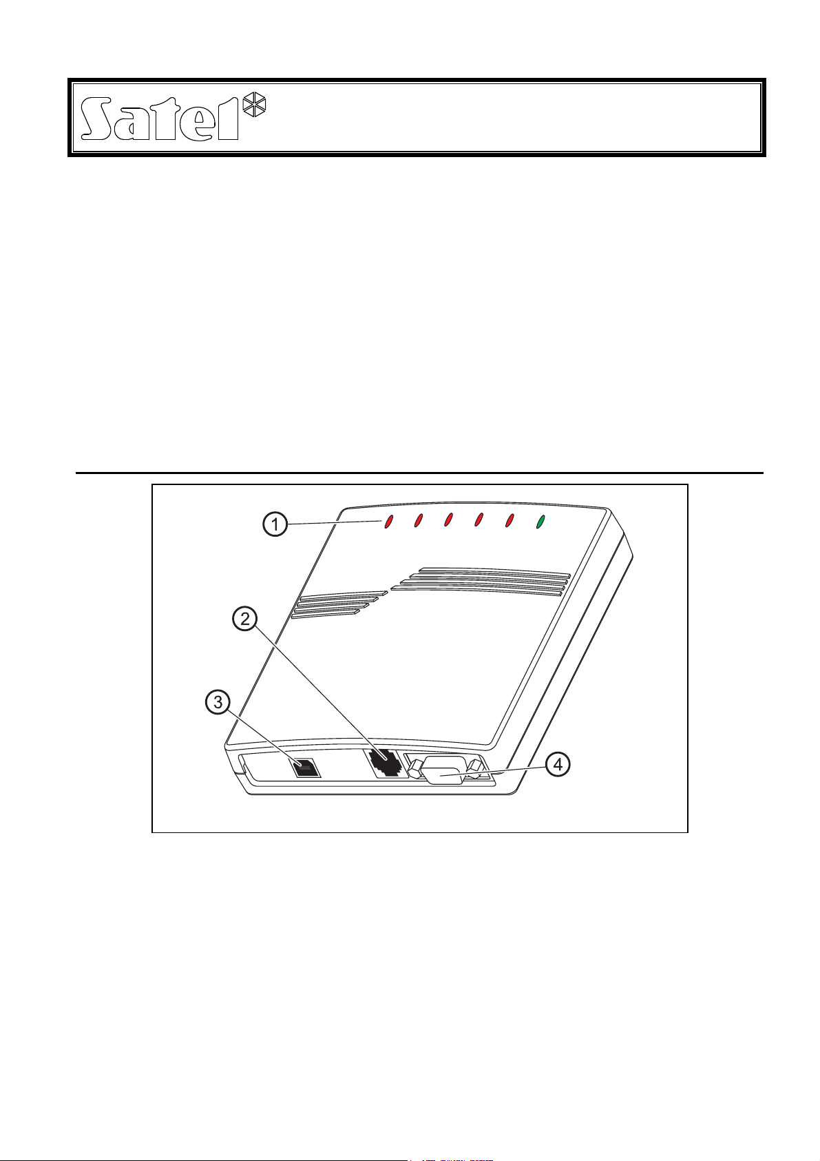
Satel ACCO-USB User manual

®
USB / RS-485 CONVERTER
ACCO-USB
acco-usb_en 05/15
The ACCO-USB converter enables the RS-485 communication bus to be connected to PC
computer through a USB serial port. It is dedicated to interfacing with the ACCO access
control system. A computer with installed ACCO-SOFT-LT program enables central
management and programming of the ACCO system. The ACCO system structure is based
on the single ACCO-KP and ACCO-KP-PS modules of the door controller. Communication in
the system is provided according to the RS-485 standard. The computer is not required for
normal operation of the system. The modules operate as fully autonomous devices, all data
necessary for work being stored in their memory. Several ACCO-USB converters can be
connected to the computer. Thus, using one computer makes it possible to simultaneously
manage several ACCO systems.
Another advantage of the ACCO-USB converter is the option to directly connect the
ACCO-USB-CZ proximity card reader. This makes adding new users an easier job for the
system administrator.
1. Converter description
Fig. 1. ACCO-USB converter.
Explanations for Fig. 1:
1 – LED indicators:
PWR - lit when the converter is connected by means of USB cable to the computer
and the computer is turned on
HEAD - lit when the ACCO-USB-CZ proximity card reader is connected to the
converter
READ - lit when the reader is waiting for proximity card to be read in
ERR - blinking when communication between converter and at least 1 module is lost
TX - blinking when data are being sent to the computer
RX - blinking when data are being received from the computer
2 – RJ-45 socket for connecting the ACCO-USB-CZ proximity card reader.

2 ACCO-USB SATEL
3 – USB socket for connecting the converter to computer.
4 – DB-9 socket for connecting the RS-485 communication bus.
2. Connecting the converter to computer
The ACCO-USB converter can be connected to a PC computer with the Windows
98/ME/2000/XP/VISTA system installed. The connection is to be made by means of the USB
cable delivered with the converter. When the connection is ready, the green LED designated
PWR will light up in the converter. The Windows system will automatically detect connection
of a new device and launch the wizard to guide the user through the procedure of installing
drivers for the new hardware. The drivers for the ACCO-USB converter can be downloaded
from www.satel.eu. Some versions of the Windows operating system may warn that the
software has not passed conformity tests. Installation of the drivers should be continued
despite these warnings. When the drivers are installed, an extra COM port will be available in
the computer. Using this port and the ACCO-USB converter, the ACCO-SOFT-LT program
will communicate with modules connected to the RS-485 bus. Two new devices will appear in
the manager window (USB <--> RS 485 Serial Converter and Acco-USB Serial Port).
After the converter is connected to the computer and drivers installed, the device will operate
service-free.
3. RS-485 communication bus
The ACCO-KP and ACCO-KP-PS door controller modules and the ACCO-USB converter
should be connected according to the bus topology (using the "star" type topology is not
recommended). The RS-485 bus structure is shown in Fig. 2.
13
A RS485 B
1
A RS485 B
2
A RS485 B
255
A
B
A
B
RTRT
Fig. 2. Diagram showing the RS-485 communication bus and how the modules are
connected to it. The DB-9 male plug for connecting the RS-485 bus to the converter
(delivered with the device) is shown from the soldering points side. The ACCO-USB
converter can be connected to the bus at any point. Resistors 100 Ωshould be installed at
the beginning and at the end of the bus.
To build the RS-485 communication bus, use the UTP (unscreened twisted pair) type of cable.
Only one pair of conductors is used. The maximum length of the bus is 1200 m and up to 255
modules can be connected to it. When connecting modules to the bus, bear in mind that an
individual address must be set on them. The address must not be repeated! None of the
modules may have address 0 set on them. The RS-485 bus should be loaded at the beginning
and at the end with resistors 100 Ω. This is particularly important when the bus is long and
the transmission rates are high.

SATEL ACCO-USB 3
Notes:
In case of any problems with communication through the RS-485 bus, connecting the
common ground of all modules and converter (pin 5) with an additional wire may prove
helpful.
For the electronics version 1.5, the ACCO-USB converter provides galvanic separation
between the computer USB port and the RS-485 bus.
4. ACCO-USB-CZ proximity card reader
The ACCO-USB-CZ proximity card reader is the CZ-EMM reader adapted to work in
conjunction with the ACCO-USB converter. The reader lead-out is terminated with the RJ-45
plug to enable connection to the converter socket. Connection of the reader is signaled by
the converter LED indicator, designated HEAD.
The reader connected to the converter makes the system administrator's work easier, as it
enables cards to be added to the users (wherever the word "card" is used in the manual, it
means the passive transponder, which may have the form of a card, key fob etc.) without
leaving the computer. In addition, the reader can be used to search for the users of
unspecified cards.
The two-color LED in the reader can signal as follows:
steady red light – normal operation of the reader;
blinking green light – waiting for the card to be placed in proximity.
The buzzer in the reader can signal as follows:
1 short beep – readout of a new card code (card added) or readout of a known card code
(searching for the user by the card).
2 long beeps – unknown card (searching for the user by the card).
Fig. 3. Reader conductor sequence in the RJ-45 plug (looking from the contacts side).
Explanations for Fig. 3:
1- red wire – head supply
2- green wire – data
3- pink wire – LED green color control
4- gray wire – LED red color control
5- yellow wire – buzzer control
6- brown wire – head operation blocking
7- blue wire – common ground
8- white wire – presence control

4 ACCO-USB SATEL
5. Technical data
5.1 ACCO-USB converter
Supply voltage ...............................................................................5 V (derived from USB port)
RS-485 bus maximum range for UTP type cable ..........................................................1200 m
Maximum number of modules connected to RS-485 bus.....................................................255
Two-way transmission scheme ......................................................................... HALF-DUPLEX
USB standard ...............................................................................................................USB 2.0
Working temperature range .............................................................................+5 °C ... +40 °C
Housing dimensions................................................................................. 125 x 114.5 x 31 mm
Weight...............................................................................................................................250 g
5.2 ACCO-USB-CZ proximity card reader
Supply voltage ...................................................................... 12 V DC (derived from converter)
Maximum current consumption .......................................................................................50 mA
Head working frequency ...............................................................................................125 kHz
Data transmission standard .....................................................................................EM-MARIN
Working temperature range ............................................................................-20 °C ... +55 °C
Housing dimensions...................................................................................... 120 x 80 x 29 mm
Weight...............................................................................................................................186 g
Latest EC declaration of conformity and product approval certificates are
available for downloading on website
www.satel.eu
SATEL sp. z o.o.
ul. Budowlanych 66
80-298 Gdańsk
POLAND
tel. + 48 58 320 94 00
www.satel.eu
Table of contents
Other Satel Media Converter manuals
Popular Media Converter manuals by other brands

ICP DAS USA
ICP DAS USA I-7530 Quick start user guide

Chord
Chord Hugo TT 2 Quick start manual

Gefen
Gefen ex•tend•it VGA to DVI Conversion Box user manual

Lenz Elektronik
Lenz Elektronik Digital plus Silver 10331 manual

Radyne
Radyne SFC4200 Installation and operation manual

Omnitron Systems Technology
Omnitron Systems Technology miConverter GX/T quick start guide

BSRF
BSRF ACH-642 quick guide

SEW-Eurodrive
SEW-Eurodrive MOVITRAC LTP-B Compact operating instructions

Allied Telesis
Allied Telesis AT-MMC1000/SP installation guide

ADF Web
ADF Web HD67B10-B2 user manual

MICRO-EPSILON
MICRO-EPSILON OT-3-GL instruction manual

VICOR
VICOR VI-200 Series Design guide & applications manual