Satel ACCO-KP User manual

ACCO-USB
USB / RS-485 converter acco-usb_en 04/22
The ACCO-USB converter enables communication between the RS-485 access control
modules bus and the computer. The computer is used to configure the modules in the
ACCO-SOFT-LT program (version 1.7.006 or newer) and to update the module firmware.
You can download the ACCO-SOFT-LT program from www.satel.eu.
1. Features
Communication via the RS-485 bus between the computer and the following modules:
ACCO-KP,
ACCO-KP-PS,
ACCO-KPWG,
ACCO-KPWG-PS,
ACCO-KP2.
Ability to configure the modules using a computer with the ACCO-SOFT-LT program
installed.
Ability to update the door controller module firmware.
Ability to connect multiple ACCO-USB converters to the computer in order to enable
management of several ACCO systems simultaneously.
Ability to connect the ACCO-USB-CZ proximity card reader.
Data transmission between the converter and the computer via USB 2.0.
Powered from the computer USB port.
LEDs to indicate the device status.
2. Specifications
ACCO-USB converter
Supply voltage............................................................................................5 V (from USB port)
RS-485 bus maximum range for UTP type cable ..........................................................1200 m
Maximum number of modules connected to RS-485 bus ....................................................255
Two-way transmission scheme......................................................................... HALF-DUPLEX
USB standard ..............................................................................................................USB 2.0
Maximum humidity..........................................................................................................93
±
3%
Working temperature range .................................................................................+5°C...+40°C
Enclosure dimensions...............................................................................125 x 114.5 x 31 mm
Weight...............................................................................................................................250 g
ACCO-USB-CZ proximity card reader
Supply voltage....................................................................................12 VDC (from converter)
Maximum current consumption .......................................................................................50 mA

2 ACCO-USB SATEL
Reader transmit frequency............................................................................................125 kHz
Outgoing data format ...............................................................................................EM-MARIN
Supported card standards...............................UNIQUE, EM4001, EM4002, EM4003, EM4102
Maximum humidity..........................................................................................................93
±
3%
Working temperature range ................................................................................-20°C...+55°C
Enclosure dimensions................................................................................... 120 x 80 x 29 mm
Weight...............................................................................................................................186 g
3. Description
Fig. 1. ACCO-USB converter.
USB socket for connecting the converter to the computer.
RJ-45 socket for connecting the ACCO-USB-CZ proximity card reader.
DB-9F socket for connecting the RS-485 communication bus.
LED indicators:
PWR –ON when the converter is connected to the computer by means of USB cable
and the computer is turned on.
HEAD –ON when the ACCO-USB-CZ proximity card reader is connected to the
converter.
READ –ON when the reader is waiting for proximity card to be read in.
ERR –flashing when communication between the converter and a module is lost.
TX –flashing when the converter is sending data to the computer.
RX –flashing when the converter is receiving data from the computer.
4. Connecting to the computer
Connect the USB ports of the computer and the converter using the USB cable included in
the kit. The green LED marked as PWR will turn ON in the converter. The Windows system
will automatically detect connection of a new device and will install required drivers for the
new hardware. After the converter is connected to the computer and drivers are installed,
the converter will operate service-free.

SATEL ACCO-USB 3
If the system fails to find the required drivers automatically, download them from
www.satel.eu.
Some versions of the Windows operating system may warn that the controller drivers
have not passed conformity tests. Continue the installation of the drivers despite these
warnings.
When the drivers are installed, an extra COM port will be available in the computer. Using
this port and the ACCO-USB converter, the ACCO-SOFT-LT program will communicate with
the modules connected to the RS-485 bus.
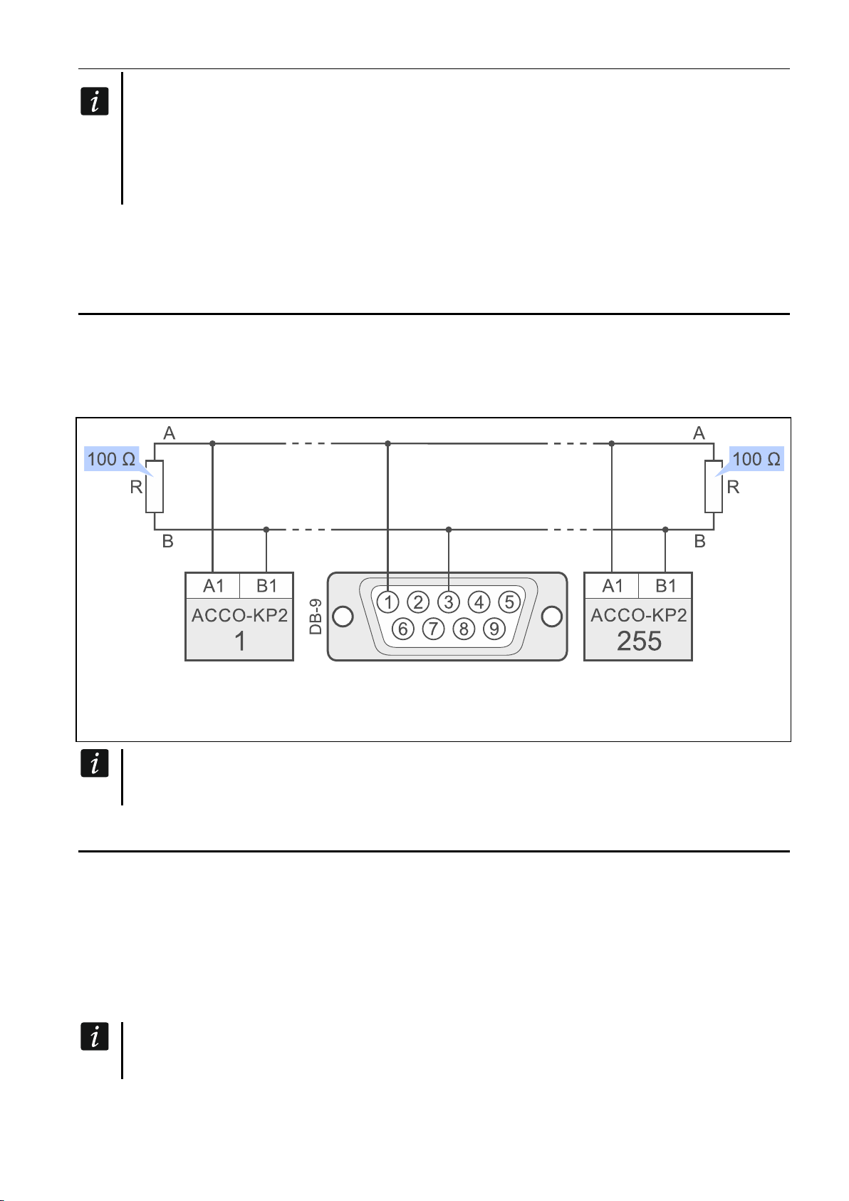
5. Connecting to the RS-485 bus
The ACCO-USB converter can be connected to the RS-485 bus of the ACCO system in any
place. Up to 255 access control modules can be connected to the bus. The converter is not
required for the ACCO system to operate. It is only used to configure the modules that work
within the system and to update their firmware.
Fig. 2. Connecting the ACCO-USB converter to the ACCO system. The DB-9 male plug for
connecting the RS-485 bus to the converter is shown from the soldering points side.
The contact is delivered with the converter.
In case of any problems with communication through the RS-485 bus, connect
the common ground of all modules and the converter (pin 5) with an additional wire.
6. ACCO-USB-CZ proximity card reader
The ACCO-USB-CZ proximity card reader is the CZ-EMM reader adapted to work with the
ACCO-USB converter.
Connect the reader RJ-45 cable to the converter socket. The red LED marked as HEAD will
turn ON in the converter.
When connected to the converter, the reader enables:
adding cards to the users,
searching for users by means of cards.
Wherever the word “card” is used in the manual, it means a passive transponder,
which may be a card, a key tag, etc.

4 ACCO-USB SATEL
The bicolor LED indicates:
ON in red –reader OK.
flashing in green –waiting for the card to be placed in proximity.
The sounder indicates:
1 short beep –readout of a new card code (card adding) or readout of a known card code
(searching for the user by the card).
2 long beeps –unknown card (searching for the user by the card).
Fig. 3. Reader conductors in the RJ-45 plug (looking from the contacts side).
Explanations for Fig. 3:
red wire –power supply.
green wire –data.
pink wire –LED green color control.
gray wire –LED red color control.
yellow wire –sounder control.
brown wire –reader operation blocking.
blue wire –common ground.
white wire –presence control.
The declaration of conformity may be consulted at www.satel.eu/ce
SATEL sp. z o.o. •ul. Budowlanych 66 • 80-298 Gdańsk • POLAND
tel. +48 58 320 94 00
www.satel.eu
This manual suits for next models
5
Table of contents
Other Satel Media Converter manuals