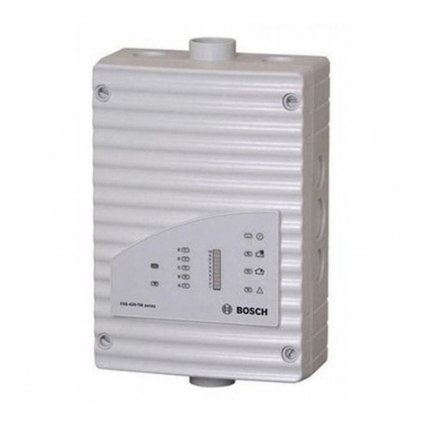
Bosch ISN-CP1-CM-W50 User manual
Other Bosch Smoke Alarm manuals
Bosch
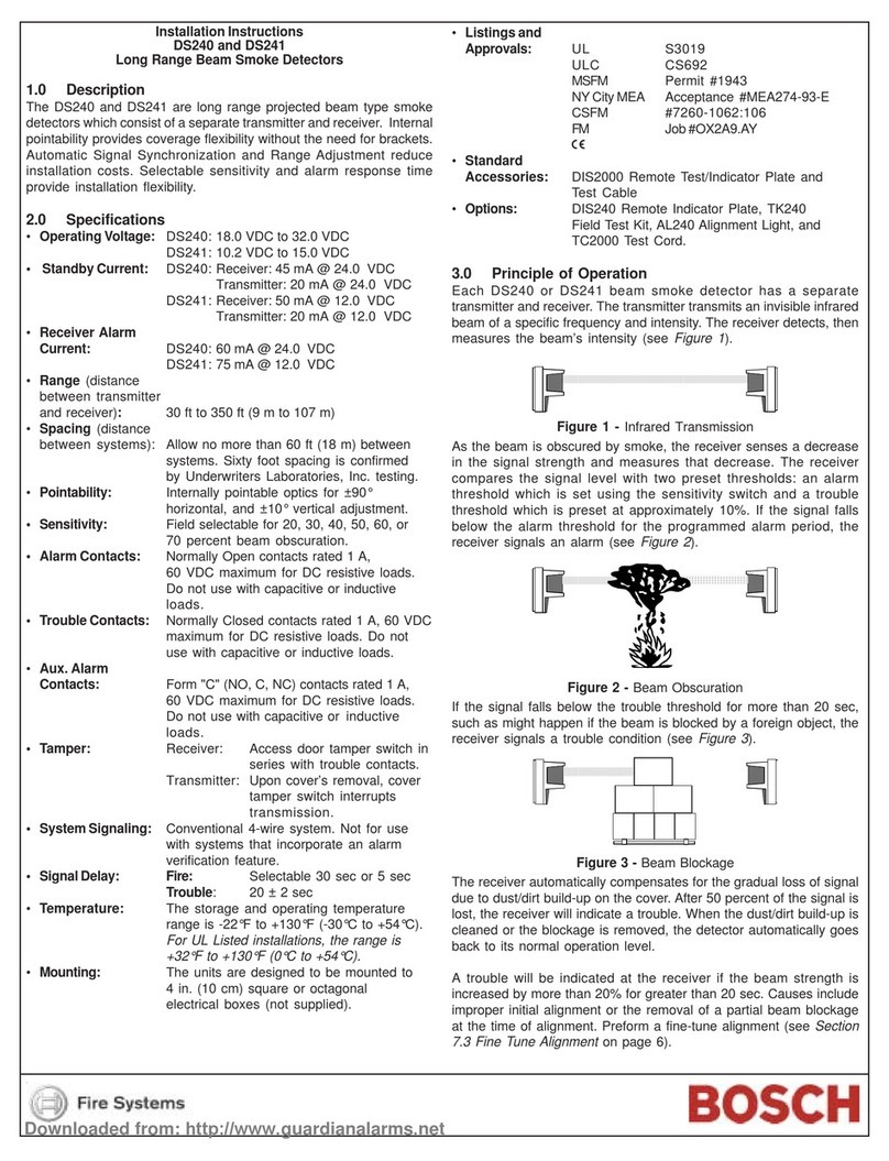
Bosch DS240 User manual
Bosch
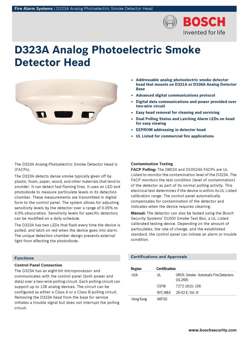
Bosch D323A Manual
Bosch
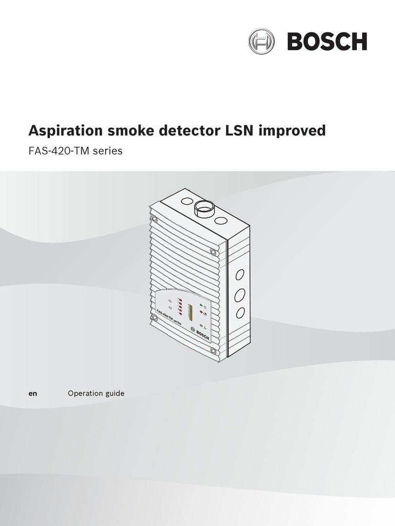
Bosch FAS-420-TM-R User manual

Bosch
Bosch FAS-420-TM User manual
Bosch
Bosch EVAX25E Product information sheet
Bosch
Bosch FCS-320-TM User manual

Bosch
Bosch D296 Series User guide

Bosch
Bosch F220 B6 User manual

Bosch
Bosch D7050DH User manual

Bosch
Bosch D1255RB/D1256RB/D1257RB User manual

Bosch
Bosch D263TH User manual

Bosch
Bosch FCS-320-TP Series User manual

Bosch
Bosch F.01U.323.385 User manual

Bosch
Bosch FERION 3000 O User manual

Bosch
Bosch FAS-420-TP Series User manual
Bosch
Bosch twinguard User manual
Bosch
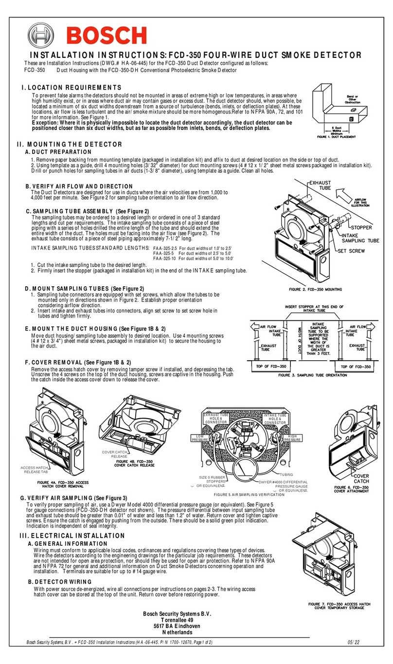
Bosch FCD-350 User manual

Bosch
Bosch FPE-1000-CITY User manual

Bosch
Bosch D7050 User manual

Bosch
Bosch D296 Series User manual
Popular Smoke Alarm manuals by other brands

x-sense
x-sense SD19-W user manual

FireAngel
FireAngel Thermoptek ST-622 user manual

teko
teko Astra-42A user guide

Siemens
Siemens PE-11C installation instructions

System Sensor
System Sensor DH500ACDC Installation and maintenance instructions

Resolution Products
Resolution Products RE612 CryptiX quick start guide
