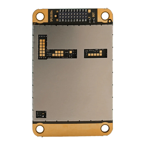
Satel SATELLINE-1AS User manual

SATELLINE-1AS and SATELLINE-2AS
Radio Data Modem
USER GUIDE

TABLE OF CONTENTS Page
1 SATELLINE-1AS and SATELLINE-2AS radio data modems 3
1.1 Radio data modem 3
1.2 RS-232 Pin Connections 4
1.3 Technical Specifications 6
2 Asynchronous Data Transmission 8
2.1 Asynchronous character 8
2.2 Effects of character length on transmission 9
2.3 Data speeds 9
2.4 Transmission 9
2.5 Reception 10
2.6 Delays during data transmission 10
3 Multi Modem Data Systems 10
3.1 Required sequence of data characters 10
3.2 Polling 10
3.3 Multi Master 11
4 Planning a Radio Modem Network 11
4.1 Factors affecting quality and distance of the radio connection 11
4.2 Radio field strength 12
5 Installation 13
5.1 RS-232 Interface 14
5.2 Supply of current 14
5.3 Mounting the antenna 15
6 Equipment 18
6.1 The connection of antennas to radio modems 18
6.1.1 Hand portable equipment 18
6.1.2 Equipment installed in vehicles 18
6.1.3 Base station 18
6.2 Cables 19
6.2.1 RF cables 19
6.2.2 Interface cables 19
7 Check List 20
Appendices
1. The timing diagram of RS-232 interface of SATELLINE-1AS and SATELLINE-2AS
radio modems
2. Selecting of radio channel of SATELLINE-2AS
3. Table of selectable radio channels
4. SATELLINE-1AS/2AS RSSI curve
**** Due to continuous product development SATEL OY reserves the right to
change specifications without notice ****
SATELLINE-1AS and SATELLINE-2AS
2

1SATELLINE-1AS and SATELLINE-2AS Radio Data Modems
This user guide is meant for SATELLINE-1AS, SATELLINE-1ASm2, SATELLINE-2AS and
SATELLINE-2ASm2 radio modems. Since their electrical function is identical and only their
housing is different, the brand names SATELLINE-1AS and SATELLINE-2AS refer to every
model mentioned above.
1.1 Radio Data Modem
MODEM
RECEIVER
TRANSMITTER
RS-232
ANALOG
13
11
6
7
9
2
3
4
5
15
1
8
TD
RTS
CTS
SGND
RD
CD
LED
ON
RSSI
+VB
DTR
GND
Fig. 1. SATELLINE-1AS radio modem
The SATELLINE-1AS radio data modem is comprised of a 450 MHz transmitter, receiver
and a modem board, housed in a compact resistant aluminium casing. It has an RS-232
interface that allows easy connection to a variety of data networks.
The SATELLINE-1ASl radio data modem has a maximum data speed of 1200 bps. It is
especially suitable for longer distances because of its better sensitivity.
The SATELLINE-2AS differs from SATELLINE-1AS by the radio part. Both the transmitter
and the receiver parts are on the same board (transceiver) and their function is based on
the synthesized radio technique. The frequency stability is better and it is possible to change
the radio channel.
The data transmission formed by radio modems resembles a cable. Unlike in cables the
data transmission is half-duplex. The delays in transmission due to the half-duplex
transmission and possible interferences must be considered when planning a system.
Should Simplex operation be required, it can be achieved by installing a SATELLINE-1T
transmitting modem and a SATELLINE-1R receiving modem.
Typical applications of radio modems are :
wReplacing a cable in situations where installation of such a cable is difficult, expensive
or even impossible.
wData transmissions between mobile or portable terminals
wWireless alarm transmission
wTelemetry
wRemote control
SATELLINE-1AS and SATELLINE-2AS
3

wTransferring text to displays
wFor use with Global Positioning System (GPS)
With two SATELLINE-1AS/-2AS radio data modems it is easy to make up point to point
connections. The power level of the transmitter is 0,5 W. It is possible to reach distances
from 2 to 30 km depending on topographical conditions and antenna locations. On
special request it is possible to manfacture transmitters with the maximum output power of
1,0 W. Country specific laws of radio communication must always be followed.
The radio data modem operates well in data networks where the same channel is used by
several mobile terminals. In such systems the protocol can be either polling mode, in which
the data communication is controlled through one of the radio modems or multimaster
mode, in which any one of the radio modems can initiate the data transmission when the
radio channel is free.
When the radio data modem is in the receiving mode, a data squelch facility is
incorporated into the modem board to effectively ignore reception of error characters to
the RD line which may have been caused by radio interference.
1.2 RS232 Pin Connections
Supply Voltage positive pole-VB15
14
Request
to
Send
IN
RTS
13
-
-
-
12
Transmit DataINTD11
Data
Set
Ready
OUT
DSR
10
Receive
Data
OUT
RD
9
Ground-GND8 Signal Ground-SGND7
Clear
to
send
OUT
CTS
6
Receiving
signal
strength
indicator
OUT
RSSI
5
LED on switching-LED ON4
LED
on
switching
-
LED
ON
3
Carrier
Detect
OUT
CD
2
Data Terminal ReadyINDTR1 OperationSD *)LineD-connector Pin
SD = Signal direction from radio data modem
IN = Input OUT= Output
SATELLINE-1AS and SATELLINE-2AS
4

Operation description of the lines pin by pin:
1 DTR operates as an ON/OFF switch of the modem "0" (0 V...-12 V)
"1" (+5 V...+12V)
2 CD indicates a signal on the radio channel exceeding the level of sensitivity of
the modem (it can record radio interferece signal).
3 and 4 Will be connected together in models with LEDs, where the most important
lines are indicated by leds.
5 RSSI measures the received signal strength of the field of the transmitting radio
(starts approximately from 0.5 V and goes up to 5 V ). The strength of the field
increases with the voltage. See appendix 4
6 CTS indicates when the radio data modem is clear to receive data via the
RS-interface
7 SGND is the signal ground
8 GND is the ground of supplying voltage
9 RD received data
11 TD input of transmitted data
13 RTS gives radio modem a request to send, starts the transmitter (answer by CTS
line)
15 Supply voltage
The RSSI (Received Signal Strength Indicator) is available on the radio data modem. This
feature indicates the level of field strength of an incoming transmission and is particularly
useful in systems that have several receivers as it is possible to select the receiving device
that has the optimum incoming signal.
The radio modem also incorporates a CD (Carrier Detect) line output which is activated
5...10 ms after the activation of the RTS line of the transmitting modem. The CD line also
indicates the presence of either a signal on the radio channel or an interference signal
above the sensitivity limit of the radio modem.
SATELLINE-1AS and SATELLINE-2AS
5

1.3 Technical Specifications
SATELLINE-1AS
Satelline-1AS complies with the following international standards:
CEPT T/R 20-04 (radio standard) and the model m2 also with prETS 300 683 (EMC
standard)
TRANSMITTER
Frequency Range 400...470 MHz
Channel Separation 25 kHz
Frequency Stability < ± 2.5 kHz (± 5 ppm)
No. of Channels 1 (Crystal)
Carrier Power 400 mW/ 50 ohm (+ 26 dBm)
Carrier Power Stability - 2 dB / + 1 dB
Frequency Deviation ± 2.5 kHz...± 3.0 kHz
Adjacent Channel Power < 200 nW
Spurious Radiations < 250 nW
Method of Modulation FSK
RECEIVER
Frequency Range 400...470 MHz
Channel Separation 25 kHz
Frequency Stability < ± 2.5 kHz (± 5 ppm)
No. of Channels 1 (Crystal)
Maximum usable sensitivity BER < 10 E-4 1AS 1ASl
300 bit/s -114 dBm -116 dBm
600 bit/s -114 dBm -116 dBm
1200 bit/s -112 dBm -116 dBm
2400 bit/s -110 dBm
4800 bit/s -110 dBm
Co-Channel Rejection > -8 dB
Adjacent Channel Selectiv. > 60 dB
Intermodulation attenuation > 60 dB
Spurious radiations < 2 nW
MODEM
Interface RS-232
Interface Connector D15 connector, female
Data Speed 300 - 4800 bit/s (1AS), 300 - 1200 bit/s (1ASl)
Modulating Signal Manchester-coded NRZ
Data Formats Asynchronous data
character length 10 or 11 bits
Data Squelch On the modem board: prevents interference from
appearing to the RD line in receiving mode
SATELLINE-1AS and SATELLINE-2AS
6

GENERAL
Operating Voltage + 10...+ 13 Vdc
Current Consumption When DTR is "0": 0.4 mA
When DTR is "1": Receiving: 55 mA
Transmitting: 330 mA
Antenna Connector TNC, 50 ohm, female
Size H x W x D 137 x 67 x 29 mm
Installation plate 130 x 63 x 1 mm
Weight 230 g
Temperature Range - 25 C...+ 55 C
SATELLINE-2AS
Satelline-2AS complies with the following international standards:
I-ETS 300 220, CEPT T/R 20-04 (radio standard) and the model m2 also with prETS 300
683 (EMC standard)
TRANSCEIVER
Frequency Range 400...470 MHz / base band 2 MHz
Channel Spacing 25 kHz
Number of Channels 16 (selectable by a Hex switch)
Frequency Stability < ± 1.5 kHz
Method of Modulation FSK
Transmitter
Carrier Power 500 mW/ 50 ohm ( + 27 dBm)
Adjustment range 20mW... 1 W / 50 ohm (factory set)
Carrier Power Stability + 1 dB / - 2 dB
Frequency Deviation ± 2.5 kHz
Adjacent Channel Power < 200 nW
Spurious Radiations I-ETSI 300 220
Receiver
Sensitivity < -108 dBm (BER < 10 E-4)
Co-channel rejection > 8 dB
Adjacent channel selectivity > 65 dB
Intermodulation attenuation > 65 dB
Spurious radiations < 2 nW
MODEM
Interface RS-232
Interface Connector D15 connector, female
Data Speed 300 - 4800 bit/s
Modulating Signal Manchester-coded NRZ
Data Formats Asynchronous data: 10 or 11 bits
Data Squelch On the modem board: prevents interference
from appearing to the RD line in receiving
mode
SATELLINE-1AS and SATELLINE-2AS
7

GENERAL
Operating Voltage + 10...+ 14 Vdc
Current Consumption When DTR is "0": 2,8 mA
When DTR is "1": Receiving: 90 mA
Transmitting: 600 mA
Antenna Connector TNC, 50 ohm,female
Size H x W x D 137 x 67 x 29 mm
Installation plate 130 x 63 x 1 mm
Weight 250 g
Temperature Range - 25 °C...+ 55 °C
Labelling information:
Ser.no. 96052938 Freq. Ch F 468.200 MHz
SATEL OY
Tel: +358-24-7331033, Fax: +358-24-7331034
wSerial number (year+ week + manufacture number)
wFrequency, set by the manufacturer. F = position of the channel switch and the
frequency corresponding 468.200 MHz
wManufacturer's contact information
2Asynchronous Data Transmission
2.1 Asynchronous Characters
Data characters can be transmitted either in 10 or 11 bits and either in 8 or 9 bit data
characters between the start and stop bits respectively. These options are factory set. Thus,
they have to be decided in advance.
Characters are formatted in accordance with the ANSI standard asynchronous characters.
See diagram below.
7 D
S
S
S
S
8 D
8 D
9 D
PL
L
L
L
P
10 bit
11 bit
S = start bit
P = parity bit
L = stop bit
D = data bit
Data transmission between the radio data modems is synchronous. The radio data modem
corrects the time difference between a clock signal from the data transmitting equipment
SATELLINE-1AS and SATELLINE-2AS
8

(DTE) and its own clock signal by adding one stop bit if required. The radio data modem
transfers parity bits as they are received.
2.2 Effects of character lenght on transmission
The transmitted data character can be either 10 or 11 bits, the length of these characters is
determined by hard wiring on the modem board.
It is important that the transmission from the data terminal equipment to the radio data
modem matches the selected character length. In the event of a mismatch transmission
errors will be shown at the receiving end as "error characters" and the data transmission will
be discontinued.
NOTE! The length of the character from the data terminal equipment must
correspond to that of the modem.
2.3 Data Speed
The data speed of the radio modem can be 300, 600, 1200, 2400 or 4800 bits/s. The
data speed is carried out by changes on the modem card.
2.4 Transmission
There are two different methods of initiating data transmission.
1 RTS/CTS handshaking
2 Data connected directly to TD line
The first method using RTS/CTS handshaking has to be used for data speeds of 2400 and
4800 bit/s. This method is initiated from the radio data modem requesting permission to
send. This is achieved by switching the RTS line from an OFF to an ON state. The
subsequent reception of data will cause the CTS line to be raised and the data transmission
will be sent on the TD line. If there is an active radio transmitter on the system with the same
radio channel the CTS line will not be raised.
The second method of transmission operates within the range of 300 to 1200 bit/s. In this
case the transmitter is switched directly to the TD line.
Should a break in transmission occur e.g. caused by a weak radio field, transmission can
only be restarted by switching off the transmission for a period of at least 20 ms before
re-sending.
SATELLINE-1AS and SATELLINE-2AS
9

2.5 Reception
The radio modem is ready to receive data when the supply voltage is switched on and the
DTR line is in the "ON" state.
Equipment connected to the radio data modem receives information about the incoming
data by detecting the change in state of the RD line. In addition, the change in state of the
CD line also allows the equipment to detect the start of a transmission.
2.6 Delays during data transmission
Delays may occur when transmitting or receiving data using the radio data modem.
These delays are:
Wake-up time DTR OFF/ON 30 ms (1AS) / 400 ms (2AS)
RTS/CTS delay 8...10 ms
Rx/Tx turn round delay 2 x 40 DBP + 20...25 m (40ms @4800 bit/s)
(50ms @2400 bit/s)
Rx ON connecting time 10 ms
Synchronization sequence 10 DBP (DBP=Data Bit Period) (e.g. 2ms @ 4800 bit/s)
3Multi Modem Data Systems
3.1 Required sequence of data characters
The data should be transferred in continuous sequences or in sequences divided into
blocks. Sequences that are too short (e.g. 1 character) should not be sent because
"overhead-information" (synchronization plus terminal address) takes a great deal of
processing time and thus slows down the data transmission. The recommended length of a
data packet is 50 - 500 characters.
The size of a system using one radio channel can be increased when the timeframe of
transmission of one terminal is short. This must be taken into account when planning the
system. The operating range of the system can be extended by increasing both the number
of base stations and the number of radio channels.
It is important that only one transmitter can be active on the same channel at the same
time.
SATELLINE-1AS and SATELLINE-2AS
10

3.2 Polling
The system can be configured as a "Master-Slave" network which allows one radio modem
to control the others in the system. Slave units can communicate to the Master during the
time allocated to that Slave by the Master unit.
The advantage of the polling mode is that collisions (i.e. simultaneous transmissions) do not
occur. The disadvantage of this method is that the transmitter of the Master is switched on
half of the time in situations where there is no data transmission from mobile to Master.
A polling protocol is not included in the transparent radio modem. It is a protocol of higher
hierarchy and supplied by the system.
3.3 Multi Master
The system can also be configured as a "Multi-Master" network. In this situation any radio
data modem can start transmission after first testing either by the CTS line or the CD line
that the radio channel is free.
The advantage of this system is that the transmitter is ON only during data transmission.
The disadvantage is that if all the mobile stations do not "hear" each another collisions may
occur.
A multi master protocol is not included in the transparent radio modem. It is a protocol of
higher hierarchy and supplied by the system.
4Planning a Radio Modem Network
4.1 Factors affecting quality and distance of the radio connection
- power of radio transmitter
- sensitivity of radio receiver
- tolerance of spurious radiations of the radio modulating signal
- amplification of transmitting and receiving antennas
- antenna cable rejection
- height
- natural obstacles
- interferences caused by radio frequencies
The transmitter power of the base model of SATELLINE-1AS/2AS is 0.5 W and sensitivity of
receiver more than -108 dBm. Thus in a flat area and in free space with a 1/4 wave
antenna (antenna amplifcation 1dBi) and an antenna height of 1 m communications from
3 km to 4 km can be achieved. Distances may be considerably shorter in situations where
there are metallic walls or other material inhibiting the propagation of radio waves.
Over long distances, problems caused by natural obstacles can often be solved by raising
the height of antennas. A ten fold increase in distance can be achieved with the use of
SATELLINE-1AS and SATELLINE-2AS
11

amplifying antennas. Frequent topographical variations over long distances may require
that at least one of the antennas needs to be raised to a height of 10 to 20 m.
As the placement of the antenna at the base station is more than 10 m from the modem it
is necessary to use a low loss cable (< 0.7 dB /10m ) in order not to waste the antenna
amplification.
If the antenna at the base station must be placed near other radio transmitter antennas (eg.
NMT, GSM etc.), an antenna filter should be added between the modem and the antenna.
Problematical connections can also be solved by adding another intermediate station for
relay. In systems with many base stations an RSSI-signal would assist in choosing the best
receiving base station. A communications network can also be built with a combination of
cables and radio data modems.
The SATELLINE-1AS/2AS radio data modem operates in the 450 MHz band where
interference caused by human beings is insignificant. Long distance interferences need not
to be taken into account even in special weather conditions.
The SATELLINE-1AS/2AS eradicates normal levels of interference that occur. However,
exceptionally high levels of interference can break through the safeguards and thus cause
errors on transmssion. In mobile vehicle applications the range of operation can be
increased by dividing the transmitted data into e.g. 50...500 bits blocks and by
retransmitting defected blocks.
A sufficent safety margin can be obtained by testing communications using an extra 6 dB
rejection at the antenna connection and with slightly less effective antennas than those to be
used in the final system. Saterm test program can be used in the communications testing. If
there is a need to measure RSSI signal during the Saterm test transmission, a message long
enough must be used eg. File Logo.TXT
4.2 Radio field strength
A successful radio transmission depends essentially on the radio field. Where field strength
is over a certain level the operational results are very good. Below this level, a few dB
marginal areas may occur in which errors begin to be generated by noise and interference
which will eventually lead to loss of connection.
Whilst in an open space, the field strength is at its optimum level although it will still be
reduced by distance. It must also be remembered that one open space has different
environmental and external factors to another and that the effects on transmission quality
must be taken into account when planning the system.
Ground, ground contours and buildings cause attenuation (loss of energy through
absorbtion) and reflections of radio waves. Buildings reflect radio waves and therefore the
effects of attenuation are not as acute when transmission is over a short distance.
SATELLINE-1AS and SATELLINE-2AS
12

However, the reflected waves will suffer a loss in power once they travel over a certain
distance, this means that they combine with the direct radio waves and interact in either
weakening or strenghtening the signal respectively. In reality attenuation can even occur at
40 dB which is very sharp and the effect on the 450 MHz frequency is about 35 cm
difference.
Please note that the RSSI tolerance is + 10 dB when using the RSSI signal of the modem to
define the field strenght. See appendices
5Installation
The radio modem is to be installed with the installation accessories supplied with the radio
modem
3. By mounting the radio
modem directly on the custo-
mer´s equipment .
2. By using the velcro-type
tape supplied with the radio
modem.
1. By using the installation plate,
that should be fastened on the
back side of the radio modem.
The installation plate can be
mounted using the holes provi-
ded on installation plate .
NOTE ! When choosing the place of mounting, please check that water can not get
inside the radio modem. It is not recommendable to mount the radio modem on a
powerfully vibrating foundation. The attachment should be lessened with help of a
resilient material.
The radio modem fulfils the technical specifications regarding temperature range
-25 °C...+55 °C. The radio modem operates also outside this temperature range but does
not necessarily fulfil all specified requirements.
SATELLINE-1AS and SATELLINE-2AS
13

5.1 RS-232 Interface
The radio modem is connected to terminal via RS-232 interface. A typical connection
where all handshaking lines are used is according to the figure below.
TD
RD
RTS
CTS
SGND
CD
DTR
+Vb
GND
11
9
13
6
7
2
1
15
8
+Vb GND
Radio modem
FUSE 630 mA slow
3
4
TD
RD
RTS
CTS
CD
2
3
4
5
7
8
25-PIN D-CONNECTOR
DTR
20
DSR
6
SGND
TD
RD
RTS
CTS
CD
2
3
5
1
7
8
9-PIN D-CONNECTOR
DTR4
DSR
6
SGND
In some systems the radio modem is connected to another data transmission equipment
(modem). The lines should in this case be connected across according to the picture below.
TD
RD
RTS
CTS
CD
2
3
4
5
7
8
TD
RD
RTS
CTS
SGND
CD
DTR
+Vb
GND
11
9
13
6
7
2
1
15
8
+Vb GND
Radio modem
FUSE 630 mA slow
DTR
20
DSR
6SGND
3
4
DSR 10
TD
RD
RTS
CTS
CD
2
3
5
1
7
8
9-PIN D-CONNECTOR
DTR
4
DSR
6
SGND
25-PIN D-CONNECTOR
5.2 Supply of current
The nominal voltage of SATELLINE radio modems is 12 V. The range of voltage is 10 - 14
V. Variations in the voltage below 1V are allowed as the radio modem is changing from
one mode to another. The operating voltage of the positive pole of the D 15 connector is
connected to the pins of the D connector and to the negative poles 7 and 8. The DTR
line in position "1" can be used as an ON/OFF switch. In this case the logical state "1"
(+5...+12 V) corresponds to ON and "0" (0 V...-12 V) to OFF.
SATELLINE-1AS and SATELLINE-2AS
14

The current consumption of SATELLINE-1ASl ja -1AS varies between 50 ... 250 mA and of
SATELLINE-2AS and -2ASx between 100 ... 600 mA. In systems where models
SATELLINE-1ASl or -1AS have been changed to models SATELLINE-2AS tai -2ASx , current
supply has to be checked. Especially in portable applications the DTR line of the radio
modem should be switched to position "0" when possible. In this case the current
consumption is approx. 0.2 mA (SATELLINE-1AS and -1ASl) or 3 mA (SATELLINE-2AS and
-2ASx). In mobile use the radio modem is required to have a direct connection to the main
vehicle battery in order to avoid additional interference.
NOTE POWER SUPPLY !
Even if the nominal output current of the power supply does not exceed it might
temporarily be unstable as the current consumption changes e.g. at starting the power
amplifier. The outputs of power supplies are often supplied with sufficient output
capacitance. The output capacitance of self built power supplies with regulators or
switched-mode power supplies might be insufficient or totally lacking.
Even if the nominal output current is considerably higher than the current consumption
of the radio modem, the voltage varies several voltages according to the changes of
the current consumption of the radio modem. This kind of function of the power supply
weakens the function of the radio modem or prohibits it totally.
Supply current should be controlled in situations where the distance is short or the
radio field strength is sufficient but the connection does not work or the number of
faulty packets is big. Quick changes in voltage can not be measured with a multimeter
as they often last for only approx. 0.5 ms. Therefore possible situations with
undervoltage should be surveyed with an oscilloscope. To ensure a reliable operation
of the radio modem the acceptable variation is below 1 V from the stable level and
continuous oscillation below 50 mV.
NOTE! Whenever connecting RS-232 interface cables to equipment, the
equipment MUST FIRST BE SWITCHED OFF.
5.3 Mounting the antenna
In great distances or in otherwise severe conditions the operation of radio communication
is dependent on antennas and their mounting. In antennas, antenna cables and terminal
adaptors there should always be a gold plated connector. Since connectors of poor quality
oxidate and increase the attenuation in the course of time appropriate connectors and
proper tools must always be used in mounting. One should also check that both the
antenna and possible fitting elements resist well weather and environmental contamination.
SATELLINE-1AS and SATELLINE-2AS
15

The metal-free zone around small antennas should be at least 1/2 m and big antennas
>5 m. The metal-free zone should be > 10 m around a relay antenna combination. This
means that, if a large network of radio modems is to be installed the best place for the
antenna is at the highest point of the building or even the use a radio mast. If a mast is
used, the antenna can be installed using a side-installation up to 2 ...3 m away from the
mast itself.
When mounting the antenna pay also attention to possible sources of interference such as:
mobile phone network base stations
local telephone network base stations
television transmitters
radio links
other radio modem networks
PC equipment (about a radius of 5 m from the antenna)
When ordering antennas please note that the antennas have been tuned to a certain
frequency range. Simple antennas and those made of stacked yagis are relatively wide
band. The frequency range of the antenna becomes narrower the more elements there are
in a yagi.
Keeping in mind the testing and service of the system it is generally useful to use rather a
long antenna cable in order to avoid the installation of radio modems near the antenna
into a place possibly difficult to access.
The antenna cable should be chosen according to the lenght bearing in mind the following
recommendations:
Length Type Attenuation
< 5 m RG58 3.0 dB/10 m/450 MHz
5 ... 20 m RG213 1.5 dB/10 m/450 MHz
> 20 m Nokia RFX 1/2"-50 0.5 dB/10 m/450 MHz
> 20 m S12272-4 0.5 dB/10 m/450 MHz
> 20 m AirCom+ 0.8 dB/10 m/450 MHz *)
*) AirCom+ cable is partly air insulated, thus an absolutely air tight connection
between the cable and the connector is required.
In great distances when the antennas are in optical positions a 6 dB power marginal is
adequate. Since the connection is built on the reflection and/or the knife-edge diffraction
the path loss can vary even 20 dB depending on the weather conditions. In this case a
short test can give a too positive result of the quality of the connection. Thus the height of
the antennas and topographical obstacles must be surveyed with great care. From time to
time an attenuating connection can be used if the data transmission protocol is well
prepared for this and the data transmission that occasionally slows down does not cause
any problems to the process.
SATELLINE-1AS and SATELLINE-2AS
16

Vertical polarized systems (antenna elements are in vertical position) are often used in
radio systems. In a system between a base station and sub-stations the vertical polarization
is generally recommendable. The antenna of the radio modem can not be mounted on the
same level with the other sub-station antennas in the same building. The best way to
distinguish from the other antennas situated in the neighbourhood is by mounting the
antennas as far as possible from each other on the altitude level. The best result is generally
obtained when all the antennas are in the same mast. With an extra ground plane between
the antennas more distinction can be obtained between the antennas in the mast.
A horizontal polarization can be used in data transmission between two points. With the
polarization attenuation more distinction is obtained in the vertical polarization interference.
The influence of the directional patterns of the antennas must, however, be taken into
consideration. If a distinction to another interfering antenna is wanted with the horizontal
polarized antennas there must be a good attenuation of the back lobe. In addition to this
the interfering radiator should be situated behind the antenna.
When the system does not demand the use of an omnidirectional antenna it is
recommendable to use directional antennas e.g. two-element yagis in firm external
installations. As the antenna amplification increases the setting of the direction of the
antenna demands for a greater care.
The base stations in high places should be supplied with 4...6 degree band-pass filters.
Please note that the higher the antenna the larger the broadcast area. The disadvantages
with a too high antenna installation at the base station are that interferences from a larger
area affect the base station and that the base station occupies the channel of a too large
area.
2AS
5 m
RS-232
Data Terminal
30 m
l
o
w
l
o
s
s
c
a
b
le
RS-232
Base Station
Computer
up to 30 km
1 ... n pcs.
1...15 m
Data Terminal
*
*
*
up to 15 km
2AS
2AS
G > 12dBi
G > 6dBi
G > 6dBi
Example of an antenna installation: By use of amplifying antennas and by installing
antennas in a high location, long distances can be reached with SATELLINE-2AS.
SATELLINE-1AS and SATELLINE-2AS
17

6Equipment
6.1 The connection of antennas to radio modems
Recommended antenna types are as follows:
6.1.1 Hand portable equipment
1/4 wave antenna (wave length on 450 MHz is about 70 cm)
Helix antenna
The antennas are mounted directly on to the antenna connector (TNC) at the top of the
radio modem.
6.1.2 Equipment installed in vehicles
1/4-wave antenna
1/2 wave antenna
Ideally the antenna should be installed vertically and it should have at least 0.5 m of open
space surrounding it. In a small system 1/4 wave antenna is adequate. There should be a
ground plane below the antenna (truck bonnet or roof). In weak conditions a 1/2 wave
antenna is the most suitable. It can be mounted at the top of a pipe, as this provides it with
as much open space as possible. In places where the antenna cannot be connected directly
to the TNC a 50 ohm coaxial cable must be used to provide the link between the TNC and
the antenna.
6.1.3 Base station
omnidirectional (1/4, 1/2 or 5/8 wave antenna)
directional (yagi or corner reflecting antenna)
The antenna should be installed in an upright position. The exact location of the antenna
depends on a number of factors from system size to physical ground countours. As a
general rule, the antenna for a base station should be located at the highest point in the
most central location of the system.
Alternatively the base station antenna can be situated inside the building, providing that the
walls of the building do not contain metal.
SATELLINE-1AS and SATELLINE-2AS
18

6.2 Cables
NOTE ! Please check, that the contact area of cable connectors is gold plated and that
the connectors used are reliable. Ageing connectors of poor quality oxidate easily and
cause malfunction of the system.
6.2.1 RF cables
If the antenna cable is shorter than 5 m a good quality 50 ohm RF cable can be used (e.g.
RG58). If a longer cable is required a low loss RF cable is highly recommendable. As a
standard cable we supply 50 ohm RG58 cable in lengths of 1 m (CRF-1) and 5 m (CRF-5).
6.2.2 Interface cables
When planning the location of the radio modem, it must be observed that the maximum
length of an RS-232 cable is 15 m. The cable must be shielded. The maximum length of
the power supply cable is 2 m. As standard cables we supply cables with either a 25 pin
connector CRS-1 F or CRS-1 M (F=female, M=male) or with a 9 pin connector CRS-2 F
or CRS-2 M. The length of the cables are 2 m and they contain both interface and power
supply cables.
There is also an interface adapter ARS-1F with a programming switch and power supply
cables available for the SATELLINE-2ASx radio modem. The interface adapter matches the
connector of the modem to a 9 pin (female) D connector. In addition there is a straight
cable with 9 pin connector, CRS-9.
SATELLINE-1AS and SATELLINE-2AS
19

7Check List
When installing and configuring a radio data modem following points should be
considered:
1. Before connecting the RS-232 interface to equipment always check that the
operating voltage is switched off.
2. Consider the exact location of the equipment for optimum results
- Place the antenna in a free space as far as possible from any source of
interference
- Do not place the modem on a strongly vibrating surface
- Do not place the modem in direct sun light or high humidity
3. The capacity and stability of the power supply must be secured so that the
current required by the transmitter is sufficient for creating a reliable connection.
4. The antenna is installated according to given instructions.
5. The settings of the radio modem correspond those of the terminal and all radio
modems of the system have the same settings and are compatible to each other.
6. The radio modems are on the same channel.
7. If the RTS/CTS handshaking is used, make sure that in the reception RTS and CTS
are in the "0"-mode (-12 V). RTS will turn on the radio transmitter in the "1"-mode.
8. If a TD transmission is used check that RTS and CTS lines are unconnected.
SATELLINE-1AS and SATELLINE-2AS
20
This manual suits for next models
1
Table of contents
Other Satel Transceiver manuals

Satel
Satel TR489 Quick setup guide

Satel
Satel SATELLINE M3-TR3 Quick setup guide

Satel
Satel SATELLINE-M3-R9 Quick setup guide

Satel
Satel GFU30 User manual

Satel
Satel SATELLINE-3AS SLR5 Supplement

Satel
Satel GFU27 User manual

Satel
Satel SATEL-TR49 SnapOn Quick setup guide

Satel
Satel SATELLINE-M3-TR8 Quick setup guide

Satel
Satel SATEL-TR4+ Quick setup guide

Satel
Satel slr6 User manual