Satronic MMG 810.1 User manual

1
A Honeywell Company
MMG 810.1 / 811.1
For 2-stage forced draught and combi oil/gas
burners
Suitable flame detectors:
- Ionisation probe
- UV sensor
- Infra-red flicker detector
INTRODUCTION
The MMG burner control box is capable of controlling
and monitoring forced draught and combi oil/gas burners
of any nominal rating (tested and approved as per EN 298).
The MMG 810.1 model 33 control boxes are also suitable for
use in stationary warm air generators (Direct air heaters
according to DIN 4794).
Different type and model designations identify the control
boxes according to varying national standards, and to some
extent, according to programme times.
TYPES AVAILABLE
MMG 810.1 Mod. 32 Art. Nr. 0640120
Mod. 33 Art. Nr. 0640220
Mod. 43 Art. Nr. 0642520
Mod. 45 Art. Nr. 0642620
MMG 811.1 Mod. 33 Art. Nr. 0640520
Mod. 63 Art. Nr. 0640420
ONSTRUCTIONAL FEATURES
The control box is enclosed in a protective, flame resistant,
transparent, plug-in type plastic housing, and includes:
– Synchronous motor with reduction gearing driving cam
switch
– Cam switch with informative, coloured programme in-
dicator
– 12-way cam switch assembly controlling the programme
sequence
– Electronic components on plug-in printed circuit
The following important indicators and operating controls
are situated on the front of the control box:
– Reset button incorporating signal lamp for malfunction
(lockout)
– Coloured programme indicator
– Central screw fastening
Burner Control Box
TECHNICAL DATA
Supply voltage 220 / 240 V (-15... +10%)
50 Hz (50 - 60 Hz)
AC frequency variations result in proportional timing
deviations
Fuse rating max. 10 A rapid, 6 A slow
Power consumption 10 VA
Max. current per output
term. 3 2A, cos ϕ 0.2
term. 4, B 2A, cos ϕ 0.4
term. 5, 6, C 1A, cos ϕ 0.4
Total load 5A, cos ϕ 0.4
Amplifier sensitivity 1 µA
Min. current from UV tube
or ionisation probe 5 µA
Flame detector cable max. 20 m cable length
Air proving switch 1 terminal 4 A, 230 V
Reset delay none
Flame detector
- Ionisation probe
- Infra-red flicker detector IRD 1020.1 end-on
- UV tube type UVZ 780 red markings
installed radially or axially
Infra red flare detector IRD 1020
Weight incl. base 350 g
Mounting attitude any
Insulation standard IP 44
Permissable ambient temp. -20°C... +60°C
Classified acc. to EN 298 BTLLXN
For external resetting, the remote reset device FR 870
(art. No. 70700) can be utilized. (Refer to doc. 750).
program timings (sec.) MMG 810.1 811.1
Model 32 33 43 45 33 63
Waiting time
at start-up tw 9 9 9 9 9 6
Max. reaction
time for air
proving switch tlw 6 6 6 6 6 5
Pre-purge time tv1 24 24 40 40 24 55
Pre-ignition time tvz 3 3 3 3 3 3
T. ignition time tz 6 6 6 8 6 5.5
Safety time ts 2 3 3 5 3 3
Time delay
term.6 / term.C tv2 10 10 10 10 10 6
EN1C-0142SZ20 0305

2
TECHNICAL FEATURES
1. Flame detection
The following types of flame detector can be employed:
– Ionisation electrode, where the mains supply provides a
neutral earth connection. Suitable for gas burners (signal
current from flame cannot be influenced by interference
from ignition spark).
– UV sensor type UVZ 780 red, suitable for gas and combi
burners.
– Infra-red flicker detector type IRD 1020.1 for all types of
burner.
2. Burner Control
– The burner controls features a low-voltage protection. If
the supply voltage dropps below 160 V during operation,
the burner switches-off. When the supply voltage raises
above 180 V, the burner performs a restart independently.
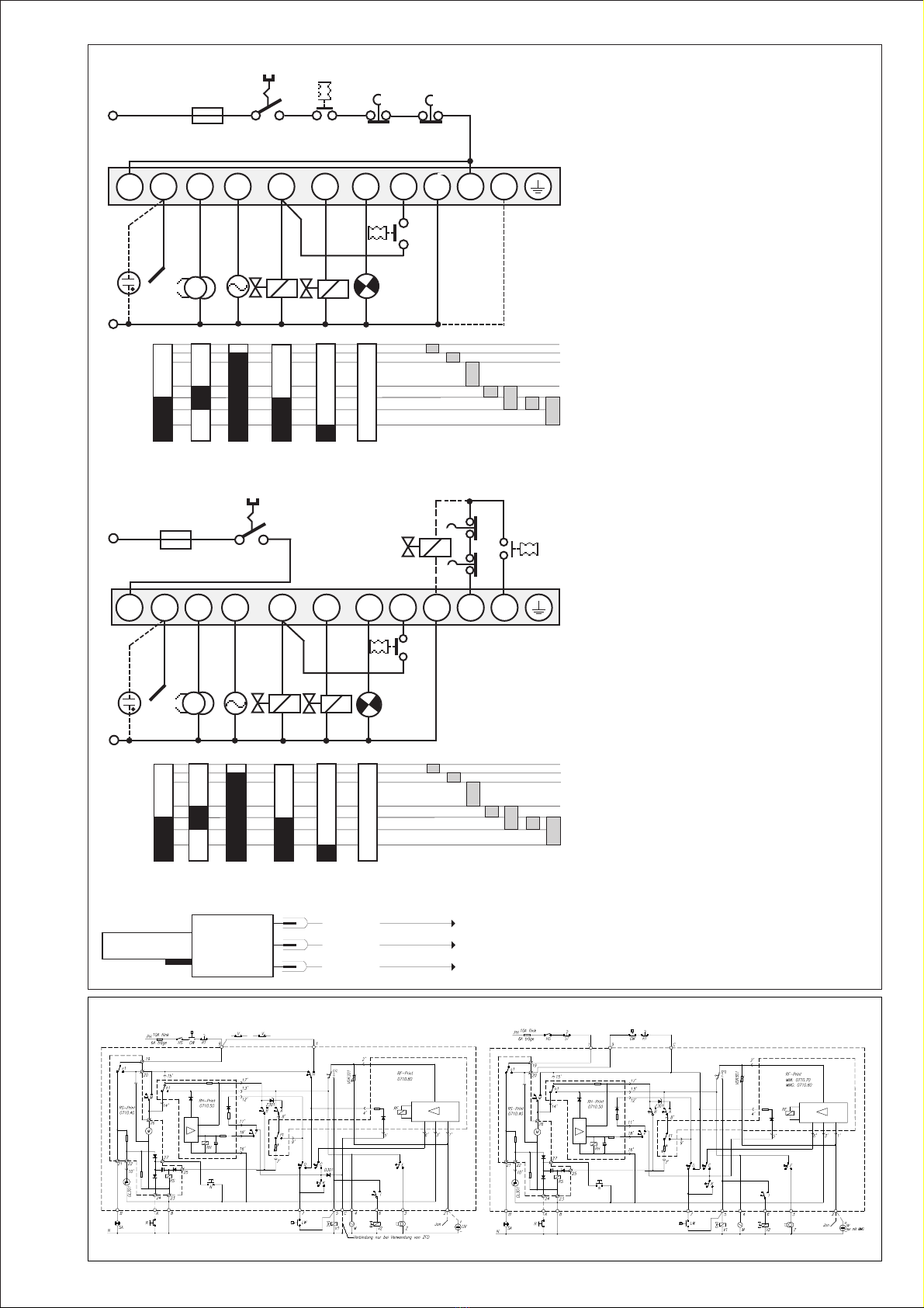
– The MMG control boxes only operate when a load is
connected to terminal 5. If the fuel valve is isolated during
the pre-purge by way of an external switch contact, a
resistor with a value of max. 22 kΩ/4 watts, must be
connected between terminals 5 and 8.
– Functional check of the air proving switch before the
start, and monitoring of the air pressure during pre-purge
as well as during normal operation. In normal use, switch
contacts with a rating of 4 A / 220 V are sufficient.
– On the MMG 810.1, switch contacts (e.g. valve end
contact) can be wired between terminals 1 and 9. These
contacts are checked for proper closure during the
burner start phase. The connection between terminals 1
and 9 must be complete during the start phase.
– The MMG 810.1 control box monitors the ignition spark
if the UVZ 780 (red) is used for flame detection, and
terminals C and 9 are wired together.
3. Safety
The design/construction and programme sequence of the
control boxes in the MMG series conform to the present
applicable European standards and regulations.
4. Installation
At the base:
– 3 earth terminals with additional terminal for burner
earthing
– 3 neutral terminals with internal permanent connection to
neutral terminal 8
– 2 independant spare terminals (S1 and S2)
– extra terminals A, B and C are standard
– 2 slide-in plates and 2 easy knock out holes plus 2 knock
out holes in the base bottom faciliate the base wiring
Please note
To assist trouble-free operation the main neutral connection
terminal 8 in the wiring base must be fully tightened. The
terminal screws are already in the undone position. To
connect a wire to the terminal, the screw only needs to be
fastened.
General:
– Can be mounted in any position, insulated as per IP 44
standard (unaffected by water spray). The control box
and detector probes should however not be subjected to
excessive vibration.
– The applicable installation regulations must be observed
during installation.
COMMISSIONING AND MAINTENANCE
1. Important
– The wiring must be checked exactly when commissioning
the installation. Incorrect wiring could damage the control
box, putting the safety of the burner system at risk.
– The chosen fuse rating must not, on any account, be
higher than the value given in the technical data. Failure
to observe this instruction could, in the case of a short
circuit, have serious consequences for the control box or
burner system.
– For safety reasons, it must be ensured that the control
box performs at least one normal shut-down during every
24 hour period.
– Switch off or disconnect the power before plugging in or
unplugging the unit.
– Control boxes are safety devices and should not to be
interfered with.
2. Functional Check
During commissioning and after an overhaul of the burner,
the following checks have to be carried out:
a) Starting test with closed manual valve and bridged gas
monitor contact:
–The device must go into a fault condition after the
safety period has elapsed.
b) Close the manual valve in operating position with the gas
monitor contact bridged.
–The device must go into a fault condition after a flame
failure.
c) Air pressure monitor contact interrupted:
–Device goes into a fault condition.
d) Bridge air pressure monitor contact before starting:
–Device must not start.
3. Trouble Shooting
Burner does not go into operation, programme indication
remains:
–Electrical connection defective.
–Thermostat or gas monitor "OFF".
Burner does not go into operation, programme indication
rotates continuously:
–Air pressure monitor defective, respectively, not in starting
position. (Working contact must be open).
– Connection term. 1 - term. 9 interrupted
– mains voltage < 180V
The automatic control switches to fault condition shortly
after the start of the pre-purge time (line within the blue
zone):
–Air pressure monitor contact does not close.
–No load on terminal 5.
–Flame signal.
Automatic control switches to fault condition during the pre-
purging (blue zone):
–No flame formation (ignition missing, valve does not
open, etc.)
–No flame signal or too weak flame signal (flame does not
adhere, poor insulation of the flame detector, burner not
properly connected to the earth conductor).
Automatic control switches to fault condition during the
operating position (red, resp. green zone):
–Flame lift-off
–Air pressure monitor contact opens
–Flame signal too weak.
MMG 810.1 / 811.1

3
SCHEMATIC DIAGRAMM MMG 810.1 SCHEMATIC DIAGRAMM MMG 811.1
IRD CONNECTION
blue
black
brown
term. 8
term. 2
term. 9
IRD 1020.1
MMG 810.1 / 811.1
1 2 A/3 4 5 6 B 7 8 9 C
N
Z M V1 V2 SA
LW
HS RT
ST
GW
max. 10 A rapid
6 A slow
Ph
tw tlw tv1 tvz tz ts tv2
1 2 A/3 4 5 6 B 7 8 9 C
max. 10 A rapid
6 A slow
Ph HS GW
ST
RT
SV
N
ZMV1V2
SA
LW
tw tlw tv1 tvz tz ts tv2
IS
UV
IS
UV
*
+
+
SCHEMATIC CONNECTION DIAGRAM AND PROCESS DIAGRAM MMG 810.1
SCHEMATIC CONNECTION DIAGRAM AND PROCESS DIAGRAM MMG 811.1
* for ign. spark
detection only
HS Mains switch
GW Gas pressure switch
ST Limit thermostat
RT Control thermostat
IS Ionisation probe
UV UV sensor
Z Ignition
M Burner motor
V1 Solenoid valve, 1st-stage
V2 Solenoid valve, 2nd-stage
LW Air pressure monitor
SA External lock-out signal
for spark detection only
SV Safety valve
tw Waiting time at start-up
tlw Max. reaction time
for air proving switch
tv1 Pre-purge time
tvz Pre-ignition time
tz Total ignition time
ts Safety time
tv2 Time delay term.6 / term. C

4
A Honeywell Company
Satronic AG
Honeywell-Platz 1
Postfach 324
CH-8157 Dielsdorf
MMG AND SOCKET
MMG 810.1 / 811.1
Reset button
Slide-in plate
ø 16 mm,
cable entry from below
Earth
UVZ 780 AND HOLDER
7596
42 138
26
30.5
ø22
r 40
48
36
4
8
22
30
10
104
50 44
29
21.8
ø13.5
HOLDER M93 +
+
+
The signal must
exceed 5 µA.
E2
0-100 µA
0-10 µA
8
E2
0-100 µA
0-10 µA
UVZ 780 red
IRD 1020.1 CHECKING THE FLAMESIGNAL
4.5
17 4
35
14
15.1
48
26
3
ø20.5
ORDERING INFORMATION
ITEM DESIGNATION ITEM NO.
Control box Type MMG 810.1 mod. 33 0640220
or Type MMG 811.1 mod. 33 0640520
Socket Wiring base S98 12-pin 75310
Slide-in plate Cable terminal plate 70502
or PG-plate 70503
Flame detector IRD 1020.1 end-on viewing 16552
Flame detector UVZ 780 red 18813
IRD mounting flange IRD Holder M93 59093
UVZ mounting flange UVZ Holder 18807
Flame detector cable 3-wire, 0.6 m 7236001
The above ordering information refers to the standard version.
Special versions are also included in our product range. Specifications subject to change without notice.
30
35 24 67
91
86
24
60
57-60
30
30
30 44
16
M4
25 5
This manual suits for next models
1
Other Satronic Control Unit manuals
Popular Control Unit manuals by other brands

Vitec Multimedia
Vitec Multimedia Litepanels ASTRA 1X1 manual

Festo
Festo CPX-AP-A-8DI-M12-5P operating instructions

Sera
Sera 620.D operating instructions

Samson
Samson TROVIS 5100 Mounting and operating instructions

RTI
RTI RCM-4 Quick reference guide

FNW
FNW 1000 WOG Installation, operation & maintenance instructions

turck
turck TX-EXTEND quick start guide

Lenze
Lenze E94AYCEO Communications manual

Sporlan
Sporlan Secondary Fluid Control Quick reference guide

ABB
ABB Relion REC670 Applications manual

AV-GAD
AV-GAD AVG064 Installation and operation manual

Dover
Dover PSG BLACKMER AIR VALVE Installation, operation and maintenance instructions