Aprilaire 76 User manual

The Model 76 is for use with any dehumidifier as an EXTERNAL CONTROL,
including Aprilaire Models 1830, 1850 Series, and 1870 Series.
The Model 76 can also be used as a communicating REMOTE CONTROL
with all Aprilaire Models 1830, 1850 Series, and 1870 Series.
(See OVERVIEW on page 3 for details.)
SAFETY INSTRUCTIONS
WARNING
1. Improper installation may cause property damage or injury. Installation, service, and
maintenance must be performed by a qualified service technician.
2. 120 Volts may cause serious injury from electric shock. Disconnect electrical power before
starting installation or servicing. Leave power disconnected until installation/service is
completed. This control is not a 120 Volt (line voltage) device.
CAUTION
1. Read all instructions before beginning installation.
2. Do not use in pool applications. Pool chemicals can damage the control.
3. Do not use solvents or cleaners on or near the display and circuit board. Chemicals can
damage components.
Model 76
Dehumidifier Control
Installation Instructions
READ AND SAVE THESE INSTRUCTIONS
1

TABLE OF CONTENTS
SAFETY INSTRUCTIONS ..................................................................1
OVERVIEW ..............................................................................3
SPECIFICATIONS .........................................................................3
LOCATION RECOMMENDATIONS ..........................................................4
INSTALLATION
Mount Control..........................................................................5
Wiring
External Control .....................................................................7
Remote Control......................................................................9
SYSTEM CHECKOUT
Power Up..............................................................................11
Test Mode ............................................................................13
Humidity/Dryness Level Setting.........................................................13
Offset ................................................................................13
Turning On and Setting the Control .....................................................14
Sequence of Operation
External Control ....................................................................15
Remote Control.....................................................................15
TROUBLESHOOTING
Error Codes
External Control ....................................................................16
Remote Control.....................................................................16
Table 2 – Error Codes ..................................................................17
Table 3 – Troubleshooting Guide ........................................................19
OVERVIEW
The Aprilaire® Model 76 Dehumidifier Control provides control of the dehumidifier from the living
space.
The control can be installed as an EXTERNAL CONTROL, allowing the homeowner to set and
adjust the humidity setting and turn dehumidification on or off from a convenient location. In this
application, the Model 76 uses an onboard sensor to monitor the relative humidity (%RH) in the
space in which it is located and displays the measured relative humidity on the digital display.
The control can also be installed to function as a REMOTE CONTROL if the dehumidifier is located
where it is not easy or convenient to access. The control can be installed in any location within
the living space, with the dehumidifier installed in the area to be dehumidified, such as a crawl
space, sealed attic, or basement. The dryness level is set on the control and communicated to the
dehumidifier. The dehumidifier communicates the measured relative humidity in the space being
dehumidified back to the Model 76 Control where it is displayed on the digital display.
SPECIFICATIONS
ELECTRICAL External Remote
Input Voltage and Current
Voltage: 24VAC +/-20%
Current: 25mA (nominal),
50mA (max.) at 24VAC
Voltage: 9VDC (supplied by
dehumidifier control board)
Output Dry Contact, Normally Open Communication
CONTROL External Remote
Control Range 40% – 80% RH 1 (less dry) – 7 (more dry)
65°F – 42°F Dew Point
Accuracy +/-5% RH See Dehumidifier Specifications
Differential 3%
Low Limit 40°F Dew Point 50°F Dry Bulb
High Limit 99°F Dry Bulb 105°F Dry Bulb
32

LOCATION RECOMMENDATIONS
As a REMOTE CONTROL, the Model 76 can be mounted wherever is convenient for the
homeowner.
Follow the recommendations below when installing the Model 76 as an EXTERNAL CONTROL.
MOUNT CONTROL
• In an area the homeowner wants to monitor and control moisture levels.
• On an interior wall.
• Approximately 5 feet off the floor.
• At least 18" from an outside wall.
DO NOT MOUNT CONTROL
• In the flow of a supply register.
• Behind doors, in corners or other dead air spaces.
• In direct sunlight, near lighting fixtures, or other appliances that give off heat.
• On an outside or unconditioned area wall.
• In stairwells or near outside doors.
• On a wall with concealed pipes or ductwork.
INSTALLATION
MOUNT CONTROL
5
FEET
NONO
18"
MINIMUM
NO
PULL APART
BACK PLATE
FRONT COVER
ANCHOR
BACK PLATE
SCREW
90-1640
90-2486
90-2485
FIGURE 1 – MOUNTING LOCATION
FIGURE 2 – DISASSEMBLE CONTROL
FIGURE 3 – MOUNT BACK PLATE
54

REQUIRED COMPONENTS
• 18-24 gauge wire (field supplied) – 4 wires required, run new cable as needed.
• (2) #8 x 1-1/2" mounting screws (supplied)
• (2) Anchors (supplied)
1. Level the back plate on the wall and mark the mounting holes and wire access location on the
wall.
2. Drill two 3/16" mounting holes and a 3/4" wire access hole. See FIGURE 3.
3. Install the drywall anchors flush with the wall surface. Note: Mounting holes on the back plate
are designed to fit on a horizontal J-box.
4. Run a 4-wire cable from the dehumidifier to the wall mount location and through the square
hole in the back plate.
5. Secure the back plate to the wall using the two #8 x 1-1/2" screws.
WIRING
WIRING MODEL 76 EXTERNAL
CONTROL TO 1830 / 1850
SERIES / 1870 SERIES
1. Disconnect power to the
dehumidifier and HVAC system.
2. Remove the wiring access cover next
to the control on the dehumidifier.
See FIGURE 4.
3. Wire the Model 76 to the
dehumidifier as shown in FIGURE 5.
4. Ensure the NO/NC switch on the
dehumidifier control is set to NO
(see FIGURE 5).
+ - A B ODT
SensorRemote
Gh Rf Cf Gs YW
HVAC EQUIP.
FLOAT
Switch
DH DH
VENT DEH
Dampers
NC NO
NO/NC
SWITCH
MODEL 76
CONTROL
DH
DH
R/+
C/-
B
A
CONTROL
PANEL COVER
CONTROL WIRING ACCESS
COVER
FILTER ACCESS DOOR
90-2489
90-1884
FIGURE 5 – WIRING MODEL 76 EXTERNAL CONTROL TO 1830 / 1850 SERIES / 1870 SERIES
FIGURE 4 – WIRING ACCESS COVER LOCATION
76

5. Snap the wiring access cover back into place, power up the dehumidifier and use the ON/OFF
button to turn the unit OFF (if ON).
90-1854
6. Press and hold the MODE button for 3 seconds to enter the Installer Set Up menu – REMOTE
DISABLED will appear on the display when Installer Set Up is entered.
7. Repeatedly press the MODE button until EXTERNAL DISABLED shows on the display.
8. Press the or button to change to EXTERNAL ENABLED.
90-1854
9. Repeatedly press the MODE button until DONE appears on the display.
WIRING MODEL 76 REMOTE CONTROL
TO 1830 / 1850 SERIES / 1870 SERIES
1. Disconnect power to the
dehumidifier and HVAC system.
2. Remove the wiring access
cover next to the control on the
dehumidifier. See FIGURE 6.
3. Wire the Model 76 to the
dehumidifier as shown in FIGURE 7.
+ - A B ODT
SensorRemote
Gh Rf Cf Gs YW
HVAC EQUIP.
MODEL 76
CONTROL
DH
DH
R/+
C/-
B
A
CONTROL
PANEL COVER
CONTROL WIRING ACCESS
COVER
FILTER ACCESS DOOR
90-2490
90-1884
FIGURE 7 – WIRING MODEL 76 REMOTE CONTROL TO 1830 / 1850 SERIES / 1870 SERIES
FIGURE 6 – WIRING ACCESS COVER LOCATION
98

4. Snap the wiring access cover back into place, power up the dehumidifier and use the ON/OFF
button to turn the unit OFF (if ON).
90-1854
5. Press and hold the MODE button for 3 seconds to enter the Installer Set Up menu – REMOTE
DISABLED will appear on the display when Installer Set Up is entered.
6. Press the or button to change to REMOTE ENABLED.
90-1854
7. Press the MODE button and DONE will appear on the display.
SYSTEM CHECKOUT
POWER UP
1. Check all wiring.
2. Plug in dehumidifier and restore power to the HVAC system.
3. Turn on/off switch on dehumidifier ON. After a 4 second start up sequence all buttons on the
Model 76 will be functional.
• The control will be OFF.
• The humidity setting will be 60% if wired for EXTERNAL CONTROL. The dryness level will be
set to 3 if REMOTE CONTROL.
• The control will display the measured humidity.
– EXTERNAL CONTROL displays humidity measured by the control in it’s installed space.
– REMOTE CONTROL displays humidity measured by the dehumidifier in it’s installed space.
90-2483
90-1636
FIGURE 8 – EXTERNAL CONTROL
MODEL 76 CONTROL
MODEL 76 LCD DISPLAY
Blinking ON + *:Control Limit Exceeded.
See Control Limits, page 15.
Solid ON:
Control On
Blinking ON:
Dehumidifying
Measured
Humidity or
Setting Control On/Off
Humidity Setting
and Offset
Adjustment
Control must be
ON to adjust offset
and setting.
SET: Shows when
humidity setting
displayed or being
changed.
OFF: Control Off
1110

MODEL 76 CONTROL
MODEL 76 LCD DISPLAY
Blinking ON + *:Control Limit Exceeded.
See Control Limits, page 15.
Solid ON:
Control On
Blinking ON:
Dehumidifying
Measured Humidity
in Remote Location
or
Dryness Level Setting Control On/Off
Dryness Level
Control must be ON
to adjust.
SET: Shows when
dryness level
setting displayed
or being changed.
OFF: Control Off
TEST MODE
1. Press and hold the ON button for 5 seconds to enter Test Mode.
a. Verify the measured humidity is displayed on the Model 76 screen.
b. Verify dehumidifier turns on, and ON blinks on the Model 76 screen.
c. Verify the *is displayed on the Model 76 screen when wired as a REMOTE CONTROL.
2. After 5 minutes or after pressing the OFF button, the control will enter Off mode.
a. Verify the dehumidifier turns off.
HUMIDITY/DRYNESS LEVEL SETTING
• The control must be ON to adjust the humidity or dryness level setting.
• The (up) and (down) buttons are used to increase or decrease the setting.
• The first press of either button will display the current setting and SET on the LCD display.
• Each subsequent push of the or button will change the setting by 1% or 1 dryness
level.
• If a button is held down, the setting will continually change by 1% or 1 dryness level every 1/2
second for as long as the button is pressed.
• The control will return to Normal Mode, displaying the measured humidity, 5 seconds after the
last button press/release.
OFFSET
When the Model 76 is installed as an EXTERNAL CONTROL, an offset can be applied to the
humidity reading to avoid discrepancies with other humidity measuring devices in the home.
Allow 48 hours for the control to acclimate before applying an offset. The control must be ON to
enter the Offset screen.
Note: This feature is not available when the
control is installed as a REMOTE CONTROL.
• Press and hold the OFF button for 5 seconds
to enter the Offset screen.
• The buttons can be used to set an
offset value between -5% RH and +5% RH.
• The control will return to Normal Mode,
displaying the measured humidity, 5
seconds after the last button press/release.
FIGURE 10 – OFFSET SCREEN
90-1638
90-2483
90-2493
FIGURE 9 – REMOTE CONTROL
1312

TURNING ON AND SETTING THE CONTROL
EXTERNAL CONTROL
1. Press the ON button.
2. Use the buttons to set the control at 59%.
Increasing the humidity setting will decrease dehumidifier run time, allowing for higher
humidity levels.
Decreasing the humidity setting will increase dehumidifier run time, allowing for lower
humidity levels.
REMOTE CONTROL
1. Press the ON button.
2. Use the buttons to set the control to a 3dryness level.
Increasing the dryness level will increase dehumidifier run time, allowing for lower
humidity levels.
Decreasing the dryness level will decrease dehumidifier run time, allowing for higher
humidity levels.
The dryness level settings can be approximated to relative humidity (%RH) using TABLE 1.
TABLE 1 – %RH (+/-5%) BASED ON DRYNESS LEVEL SETTING & INDOOR TEMPERATURE
Dryness Level Setting
Indoor Temperature (°F)
65 70 75 80
1 84% 71% 60%
287% 73% 62% 52%
375% 63% 54% 45%
465% 55% 46% 39%
5 56% 47% 40% 34%
6 50% 42% 36% 30%
743% 36% 31% 26%
Note: This table is for reference only.
SEQUENCE OF OPERATION
EXTERNAL CONTROL
Normal Mode
• When the measured humidity is greater than the setting, the control will activate the dehumidifier
output, the dehumidifier will begin dehumidifying and ON will blink on the LCD display.
• When the measured humidity falls 3% below the setting, the control will deactivate the
dehumidifier output, the dehumidifier will stop dehumidifying and the LCD will display a solid ON.
Control Limits
• If the control measures a dew point below 40°F OR a temperature above 99°F, the control
will deactivate the dehumidifier output if actively dehumidifying, the dehumidifier will stop
dehumidifying, and ON and *will blink on the LCD screen.
• The control will resume normal operation when the measured dew point is greater than 45°F or
the measured temperature is below 94°F, whichever control limit was exceeded.
REMOTE CONTROL
Normal Mode
• Once during every Cycle Period (set by the dip switches in the dehumidifier) the dehumidifier
blower and dehumidifier damper output will turn on and sample the air in the area served by
the dehumidifier. Sampling will also occur whenever the dryness level setting is increased on
the Model 76 Control.
• After three minutes, the dew point of the incoming air is measured and compared to the
dryness level set on the Model 76 Control. If the dew point of the incoming air is above the
setting, the compressor turns on and ON will blink on the Model 76 screen.
• The dew point of the incoming air is continuously monitored during compressor operation.
When the dew point of the incoming air falls below the dryness level setting, the dehumidifier
compressor and blower will turn off and ON will stop blinking on the Model 76 screen.
Control Limits
The control limits are determined by the dehumidifier.
• If the dehumidifier senses incoming air below 50°F or above 105°F, the dehumidifier will stop
compressor operation if actively dehumidifying, and ON and *will blink on the LCD screen.
• The dehumidifier will resume normal operation when the measured incoming air to the
dehumidifier is between 55°F and 100°F.
1514

TROUBLESHOOTING
Technical Support is available Monday through Friday, 7:00 a.m. to 5:00 p.m. CST, at
(800)334-6011. Use the guide on the following pages to help find and correct system faults.
Contact Technical Support before replacing the control or for additional troubleshooting.
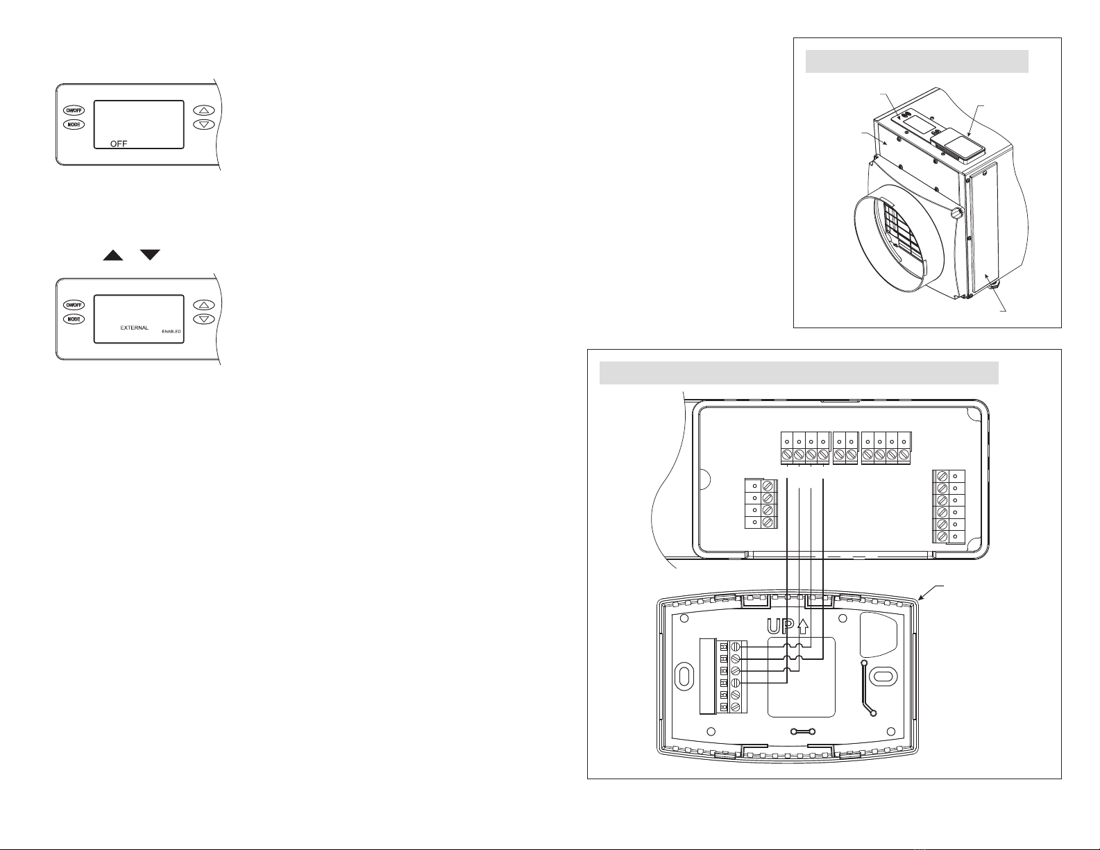
FIGURE 11 – EXTERNAL CONTROL
ERROR CODE SCREEN
FIGURE 12 – REMOTE CONTROL
ERROR CODE SCREEN
90-1645
90-1645
ERROR CODES
EXTERNAL CONTROL
When the control detects an internal error,
it will stop controlling, deactivate the
dehumidifier output, and the LCD will display
the Error Code. See FIGURE 11. The control
will attempt to recover from the error every
10 minutes. The Error Code will continue to be
displayed as long as the error condition exists.
Button presses are not registered when in
Error Mode. Cycling power to the control will
not clear the code and the control will need to
be replaced.
REMOTE CONTROL
When there is a dehumidifier or control
communication fault, all dehumidifier outputs
will turn off and the Model 76 LCD will display
an Error Code. See FIGURE 12 for an example.
The faults can either be critical or non-critical.
Any fault will result in all dehumidification
outputs turning off. A critical fault is cleared
by repairing the fault and cycling power using
the on/off switch on the dehumidifier. A non-
critical fault is cleared by repairing the fault
and cycling power to the dehumidifier is not
required. See TABLE 2 for the error codes and
required action.
TABLE 2 – ERROR CODES
Error
Code Failure Mode Action Reset
E1
Internal
Humidity or
Temperature
Sensor Open or
Shorted
1. Check the connection between the sensor board and control
board.
2. If connection okay, replace sensor board, Part No. 5460.
Cycle
Power
E2
High
Refrigeration
Pressure
1. Verify that the fan works, the backflow damper swings freely
and there is no blocked or restricted ductwork.
2. If the fault persists, call Technical Support.
Cycle
Power
E3
Model 76
Remote Control
Communication
Loss
1. Check connections between Model 76 and dehumidifier
control board. Terminals should be fully inserted and secured
in the control board and Model 76 control terminals.
2. If connections are correct and secure, turn off the
dehumidifier and remove the Model 76. Use a short section
of 4-wire cable to reconnect the Model 76 to the control
board. Turn the dehumidifier back on and increase the
dryness level setting on the Model 76. If the dehumidifier
turns on, the problem is with the wiring between the
dehumidifier and control.
3. If the dehumidifier does not turn on, call Technical Support.
Self-
Correcting
E4 Insufficient
Capacity
1. Check the frost sensor connection at the power board.
Terminal should be fully seated on the power board pins.
2. Remove the side access panel and verify that the sensor is
secured to the suction line.
3. If the sensor is connected and secured to the refrigeration
line proceed to the next step.
4. Reset the fault by cycling power to the dehumidifier.
5. Turn the humidity setting down (below room/home humidity
level) to make a dehumidification call.
6. Allow the fan and compressor to run for approximately
10-15 minutes and then enter diagnostic test mode by
simultaneously pressing the and MODE buttons for 3
seconds. The LCD will display the temperature measured by
the internal sensor while also displaying AIR SAMPLING and
ON, the humidity measured by the internal sensor while also
displaying %RH and ON, and the frost sensor temperature
while also displaying ON. Scroll through these values and by
using the buttons.
7. Record values and call Technical Support.
Cycle
Power
E5
High
Temperature
Thermistor
Failure
1. Check the high temperature sensor connection at the power
board. Terminal should be fully seated on the power board pins.
2. Remove the side access panel and verify the sensor is not
damaged and connected to the refrigeration line coming
from the compressor.
3. If the sensor is connected and secured to the refrigeration
line, contact Technical Support.
Cycle
Power
1716

TABLE 2 – ERROR CODES
Error
Code Failure Mode Action Reset
E6
Low
Temperature
Thermistor
Failure
1. Check the low temperature sensor connection at the power
board.
2. Remove the side access panel and verify the sensor is not
damaged and connected to the suction line.
3. If the sensor is connected and secured to the refrigeration
line, contact Technical Support.
Cycle
Power
E7 Float Switch
Open
1. Empty the condensate pan.
2. Check the float switch connection at the control board.
3. If not using a float switch, verify jumper is between float
switch terminals on dehumidifier control board.
4. If the problem persists, replace the float switch.
Self-
Correcting
E8
Inlet Air
Temperature Out
of 50°F – 104°F
or dew point
below 40°F
1. Verify all ductwork is properly sealed.
2. If no signs of leak points, contact Technical Support.
Self-
Correcting
E9
Outdoor
Temperature
Sensor Open or
Shorted
1. Check the sensor connection at the power board.
2. Remove the wires from the terminals and measure the
resistance. An short circuit will have a resistance very close to
0 Ohms and an open circuit will have a very high resistance.
The table below can be used to approximate the resistance
based on outdoor temperature.
Outdoor Temperature Resistance
0°F 84,500 Ohms
20°F 46,000 Ohms
40°F 26,000 Ohms
60°F 15,500 Ohms
80°F 9,500 Ohms
100°F 6,000 Ohms
3. If the sensor is not reading correctly, replace the sensor, Part
No. 8052.
Self-
Correcting
E0 High Dew Point
Alert
1. Verify unit is functioning properly by self-correcting
diagnostic codes.
2. If there has been an environmental event causing a spike in
moisture/humidity, allow the dehumidifier to continue to run.
3. If the fault persists, contact Technical Support.
Cycle
Power
TABLE 3 – TROUBLESHOOTING GUIDE
Symptom Possible Reason Troubleshooting Procedure
No power to the
control.
Incorrect wiring. Verify wiring connections between control,
dehumidifier and HVAC system (where applicable).
No power to dehumidifier. • Verify that the dehumidifier power switch is ON.
• Verify the circuit breaker has not tripped.
No power to HVAC
equipment.
• Verify HVAC system switch is on.
• Verify the circuit breaker has not tripped.
Control does
not turn on
dehumidifier
output.
Incorrect wiring. Verify wiring connections between control and
dehumidifier.
Blank display
or missing
segments during
Test mode.
LCD error. Replace control.
Display shows Er.Control detected an internal
error. The control will need to be replaced.
Display shows
E1-E9.
Dehumidifier or
communication error. Use TABLE 2 to troubleshoot fault.
Inaccurate
humidity reading
when using
External Control.
Control recently installed
after being stored in an
uncontrolled temperature
and humidity environment.
Allow 48 hours for control to acclimate.
Offset has been applied to
the humidity reading. Change the offset.
Control is mounted in direct
sunlight, above a heat or
humidity source, or in the
path of a supply register.
Relocate the control.
1918

AprilairePartners.com
P.O. Box 1467
Madison, WI 53701-1467
800.334.6011 F: 608.257.4357
Printed in USA
©2019 Aprilaire – Division of Research Products Corporation
61001718 B2208436A 4.19
20
Other manuals for 76
2
Table of contents
Other Aprilaire Control Unit manuals
Popular Control Unit manuals by other brands

Aclara
Aclara Synergize RF installation instructions

Reliance electric
Reliance electric GV3000 instruction manual

National Instruments
National Instruments PXIe-8522 user manual

Reliable
Reliable N2-Blast DDX-LP PrePaK Instructions for installation, operation care and maintenance

Honeywell
Honeywell TR80 Installation and operating guide

FMS
FMS CMGZ411 operating manual