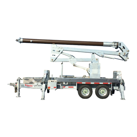
Sauber 1566 User manual

Operation and
Maintenance Manual

Valued Customer:
Please review the following manual. If you have any ques-
tions or need assistance of any kind, please contact your
account representative toll free:
Voice Communications.............................. 800) 323-9147
Fax Communications................................. 800) 833-3264
We welcome feedback on your manuals and our marketing
communications. We need, and are driven to constantly improve.
If you have any suggestions, comments or criticisms we’d love to hear from you.

Custom Engineered For National Grid
Preface
Thank you for choosing Sauber Mfg. Co.. You have purchased a trailer designed and built with care. With
minimal maintenance and by understanding its operation, your new trailer will provide you with years of excellent
service. We welcome your suggestions for improvement and stand willing to assist you if any questions arise dur-
ing its operation. If we can help in any way, please contact your account representative toll free:
Website: SauberMfg.com
Voice Communications: (800) 323-9147
Fax Communications: (630) 365-6610
The following manual provides important safety information and instruction. Please read this manual before oper-
ating your new trailer. It is important to follow safety instructions and cautions.
We acknowledge that not every situation or combination of tow vehicle and trailer can be addressed, therefore we
ask that you use sound judgment after reading the following outlines.
Some components may be produced by a third party. When available, separate service manuals and instructions
may apply.
Serious Hazards
Loss of control of the tow vehicle/trailer combination could result in serious injury or death. The most common
causes for loss of control include:
•Failure to adjust driving behavior when towing a trailer
•Immoderate speed – Driving too fast for the conditions
With ideal road conditions, the maximum recommended speed for safely towing a trailer is 60 mph. If you drive
too fast, the trailer is more likely to sway, increasing the possibility for loss of control. In addition, it is possible that
the tires may overheat, increasing the chance of a blow out.
Decrease your speed as road, weather, lighting, and other conditions decline.
•Improper sizing of the tow vehicle for the trailer
Trailers that weigh too much for the tow vehicle can cause unsafe stability issues which can lead to loss of control
and a serious accident. Know your vehicle tow rating and Gross Combination Weight Rating (GCWR.) Vehicle
manufacturers will provide you with maximum towing capacities, as well as the GCWR. The additional strain put
on the engine and drive-train of the vehicle may also lead to serious maintenance problems. For these reasons,
the maximum towing capacity of your towing vehicle should not be exceeded. The towing capacity of your vehicle
can be found in the tow vehicle's Owner's Manual.
This information is the property of Sauber Mfg. Co. and is intended for customer use only.
Operation & Maintenance Manual
Model 1566 Self-Loading Trailer
10/2014
Page 1

Use of a hitch with a load rating less than the load rating of the trailer can result in loss of control and may lead to
a serious accident. Ensure that your hitch and tow vehicle are rated for the Gross Vehicle Weight Rating (GVWR)
and tongue weight of your trailer.
•Overloading and/or improper weight distribution
The total weight of the load you put in or on the trailer, plus the empty weight of the trailer itself, must not exceed
the trailer's Gross Vehicle Weight Rating (GVWR.) If you do not know the empty weight of the trailer plus the car-
go weight, you must weigh the loaded trailer at a commercial scale. In addition, you must distribute the load in the
trailer such that the load on any axle does not exceed the Gross Axle Weight Rating (GAWR.) The GVWR and
GAWR are located on the OEM certification and VIN label attached to the front frame of the trailer.
Never exceed the trailer Gross Vehicle Weight Rating or the Gross Axle Weight Rating. Do not load a trailer so
that the weight on any tire exceeds its rating.
Improper front/rear load distribution can lead to trailer sway and poor handling conditions. Undesirable trailer
sway results from tongue weights that are too low, while tow vehicle instability results from tongue weights that
are too high.
Uneven left/right load distribution can cause tire, wheel, axle or structural failure. To the extent possible, be sure
your trailer is evenly loaded left/right. Towing stability also depends on keeping the center of gravity as low as
possible.
Make certain the tongue weight is within the allowable range. Keep the center of gravity as low as possible.
•Unsecured loads
Your trailer may be designed for specific cargo, such as reels, or poles. If your trailer is designed for specific car-
go, do not carry any other cargo such as people, hazardous substances or containers of flammable materials.
It is important to avoid shifting cargo. The trailer ride can be bumpy and rough. Securing cargo so that it does not
shift or bounce out of the trailer is imperative. Tie down all loads with proper sized fasteners. Always secure doors
or lids if present on your trailer by securing it's latch.
•Improper braking and steering under sway conditions
When towing a trailer, you will have decreased acceleration, increased stopping distance, and increased turning
radius. The trailer will change the handling characteristics of your towing vehicle, making it more sensitive to
steering inputs and more likely to be have its stability affected in windy conditions or when passed by large vehi-
cles. You will also need to adjust driving accordingly, i.e. taking a longer distance to pass and allowing for in-
creased braking distances, etc.
Common sense measures may be necessary, such as; being alert for slippery conditions, anticipate trailer sway
and be ready to reduce speed, use small, trim-like steering adjustments to re-gain control, check rear view mirrors
frequently to evaluate trailer towing and traffic conditions, use a lower gear when driving downhill or on long
grades, be aware of your trailer height at all times, especially when approaching bridges and roofed areas.
•Improper or incorrect coupling of the trailer to the hitch
It is critical that the trailer be securely coupled to the hitch, and that the safety chains and emergency break-away
cable (electric brakes) and air hoses (air brakes) are correctly attached. Uncoupling of the trailer during transit can
lead to a serious accident or a fatality.
This information is the property of Sauber Mfg. Co. and is intended for customer use only.
Operation & Maintenance Manual
Model 1566 Self-Loading Trailer
10/2014
Page 2

Ensure that the pintle hook capacity rating, including installation, is sufficient for the GVWR and the tongue weight
of the trailer being towed. Make sure that the pintle hook is physically compatible with the trailer drawbar. Compat-
ibility information is available from the pintle hook manufacturer.
Observe the drawbar and pintle hook for wear, corrosion and cracks before coupling. Replace worn, cracked or
corroded components per the manufacturer's recommendations.
Ensure the hitch drawbar and pintle hook are installed with grade-8 fasteners and are properly torqued before
coupling to the tow vehicle.
Do not move the trailer if any of the following conditions appear:
•The drawbar is not secured and locked to the pintle hook.
•The safety chains are not secured to the tow vehicle. If your trailer detaches from the pintle hook for any
reason, we have provided safety chains so that control of the trailer can still be maintained. Improper rig-
ging of the safety chains could result in loss of control. Fasten chains to the frame of the towing vehicle.
Do not fasten chains to any part of the hitch unless the hitch has special holes or loops specifically de-
signed for that purpose. Cross chains underneath hitch and coupler with enough slack to permit turning
and to suspend the trailer tongue should it become detached.
•The trailer jacks are not fully retracted.
Do not tow the trailer on the road until:
•The trailer breakaway system is operational
The breakaway switch must be connected and verified. If equipped with electric brakes, your trailer will be
equipped with a breakaway system that can apply the brakes on your trailer if it becomes detached from the tow
vehicle for any reason. The breakaway system, including the battery, must be in good condition and properly
rigged to be effective. An inoperative breakaway can result in a runaway trailer. The breakaway cable must be at-
tached to the towing vehicle and not to any part of the hitch. Before towing the trailer, test the system. If the sys-
tem is not working, do not tow the trailer. Have it serviced or repaired.
•Tires and wheels are checked
Failure to maintain proper tire condition and pressure can lead to loss of control.
Just as with your tow vehicle tires, the trailer tires and wheels are important safety items. It is essential to inspect
them before each tow.
If a tire is found to include defects such as a bald spot, bulge, cut, cracks or is showing any cords, replace before
towing. Have the tires inspected by qualified persons. Check inflation pressure on all tires prior to towing.
Failure to keep lug nuts tightened properly may cause the wheels to be seated to the hub improperly. Before
each tow, check to make sure they are properly torqued. The proper torque for lug nuts is listed in this manual
and available from the manufacturer. Use a torque wrench to tighten the lug nuts, use a crisscross star pattern.
Lug nuts are also prone to loosen after first being assembled. When driving a new trailer (or after wheels have be
remounted,) check to make sure they are tight after the first 10, 25, and 50 miles of use and before each tow
thereafter.
This information is the property of Sauber Mfg. Co. and is intended for customer use only.
Operation & Maintenance Manual
Model 1566 Self-Loading Trailer
10/2014
Page 3

•The trailer lights and brakes are connected and checked
Be sure the trailer brakes and all the lights on your trailer are functioning properly before towing your trailer.
Brakes and lights on a trailer are controlled via a connection to the tow vehicle.
Electric Brakes
Check the trailer brake lights by having someone operate the brake and turn signals on the tow vehicle
while you visually verify it is functioning. If your trailer has electric brakes, your tow vehicle will have an electric
brake controller that is required to be installed at the driver's position that sends power to the brakes. To check
the condition of the electrical brake system, pull the breakaway pin and check for the illumination of the green LED
indicator light. When fully lit, the battery is charged and the system wiring is correct. To test this system, operate
the brake controller while trying to pull the trailer at a speed of less than 5mph to verify they are operating and you
can feel them engage.
If your trailer has hydraulic, or “surge” brakes, pull the emergency breakaway lanyard to check the operation of
the emergency brake system.
•Proper Tongue Weight is established
It is critical to have a portion of the trailer load carried by the tow vehicle. The trailer tongue should always exert a
downward force on the hitch. Proper tongue weight is essential to good trailer tracking and safe operation. If too
little weight is distributed to the tongue, towing will be erratic. Too much tongue weight may overload the towing
vehicle’s rear axle or the pintle hitch rating. Ten to twenty percent weight transfer is considered a normal range.
Smaller, single axle trailers can transfer weight on the high side of this range. Larger, multiple axle trailers are de-
signed to transfer less because of the limited capacity of the towing vehicle’s rear axle.
When necessary, tongue weight can be controlled by distributing the load or by adjusting the pintle eye.
Even loading is ideal, but when this is not possible, place more weight toward the trailer front to provide a safe
tongue weight. Be aware that too much tongue weight from an uneven load can overload tow vehicle compo-
nents. It is incumbent upon the operator to provide a safe, towable tongue weight without excessive hitch weight
transfer that could place the tow vehicle in a non-compliant condition. If your trailer is equipped with an adjustable
eye, lowering it will generally increase tongue weight while raising it will decrease tongue weight - especially on
multi-axle models. Additional loading instructions may be included with your trailer, and should be followed.
Once the trailer pintle eye is secured in the towing vehicle hitch, cross the safety chains and connect them
to the rings provided at the towing vehicle bumper. Insert the electrical connection cord and check trailer lighting.
Connect the air glad hands if present and check brake operation. Ensure the trailer axle(s) do not exceed their
GAWR and the entire trailer and load does not exceed the GVWR rating.
•Grounding
Your trailer is equipped with a bronze grounding lug. When the trailer is used near energized conductors
the trailer must be grounded. A grounding lug is provided to help you follow your company’s safety prac-
tices.
This information is the property of Sauber Mfg. Co. and is intended for customer use only.
Operation & Maintenance Manual
Model 1566 Self-Loading Trailer
10/2014
Page 4

•Outriggers
Stability is an important part of safe trailer use. Because the towing vehicle can provide additional stabili-
ty, leave it connected to the trailer when you can. Set the rear outriggers to their lowest level. If you need
to decouple the towing vehicle, lower the front jack slightly, set the outriggers and then raise the jack to
seat the outriggers firmly in the ground.
•Wheel Chocks
Set the chocks at each rear wheel in the direction of the expected load or grade.
•Do not modify your trailer
Your trailer is a custom engineered piece of equipment. Essential safety items can be damaged by altering your
trailer. The simplest modifications, such as driving a screw or punching a hole to install a hanger can inadvertent-
ly damage an electrical wire or other hidden component. Before making any alteration to your trailer, contact
Sauber Mfg. Co. at (800) 323-9147.
Hand Pump Operation
The power for mechanized trailer operations is supplied by hydraulic hand pumps. A knob located on the
side of the pump provides a mechanism to hold or release pressure. Pressure can be held by rotating the knob
clockwise until tight. Pressure is released by gradually opening the valve; do not open the valve completely or
quickly as this will provide more retraction speed than is desirable or safe. Always fully tighten the knob by rotat-
ing it clockwise for travel operations.
Reel Loading via Self-Loading (preferred)
Raise the reel carriage to full elevation and remove the safety cylinder stops via the lever on the right side
of the trailer. With the safety stops disengaged, lower the reel carriage to its fully lowered position. Lower the
spring loaded reel bar retainer at each side of the bronze saddles. Remove the reel bar and insert sleeves and
positioning collars. Insert reel bar into the reel centering reel on bar if possible. Install the insert sleeves over the
reel bar and into the reel bar receiver hole as far as possible both sides. Apply the hinge positioning collar directly
behind the sleeve flange and tighten the locking bolt to 30 ft-lbs of torque. If a torque wrench is not available, you
can approximate this specification by tightening the bolt by hand (finger tight) and then applying one complete turn
of the bolt. Position the trailer with the bronze saddle assemblies in position to elevate the reel. Lower the rear
jacks fully and elevate trailer tongue slightly to seat outriggers.
Reel Loading via Mechanized Equipment (alternate)
Maximum Lifting capacity of the reel collars with hooks is 8000#. The item # of these are 1250-1 with lift-
ing hooks. Although your trailer was designed to be loaded by the self-loading apparatus, it can be loaded by via
a load line and sling attached to mechanized equipment. Operators must ensure that they maintain safe dis-
tances and observe their company's overhead lifting guidelines at all times. For this operation you will need
Sauber reel collars equipped with lifting hooks. Maximum lifting capacity of the reel collars with hooks is 8000#.
The item number of these are Sauber 1250-1 with lifting hooks. Install the insert sleeves over the reel bar and
into the reel bar receiver hole as far as possible. Apply the hinge collar directly behind the sleeve flange and tight-
en the locking bolt to 30 ft-lbs of torque. If a torque wrench is not available, you can approximate this specification
by tightening the bolt by hand (finger tight) and then applying one complete turn of the bolt. Do not exceed the
rating on the hook.
This information is the property of Sauber Mfg. Co. and is intended for customer use only.
Operation & Maintenance Manual
Model 1566 Self-Loading Trailer
10/2014
Page 5

Raise the reel carriage to full elevation and remove the safety cylinder stops via the lever on the right side of the
trailer. With the safety stops disengaged, lower the reel carriage to its fully lowered position. Lower the spring
loaded reel bar retainer at each side of the bronze saddles. Lower the rear jacks fully and elevate trailer tongue
slightly to seat outriggers. Use a continuous round sling to elevate the reel bar into the lowest available reel car-
riage position, ensuring that the reel bar is positioned in the same set of casting saddles on each side. Ensure
that ground clearance is adequate for the intended terrain.
Securing the Reel for Transport - Both Loading Methods
Raise the reel to full elevation and engage the safety stops. Because these stops are a secondary safety device,
do not release cylinder pressure. Always store and tow trailer with hydraulic pressure applied to the cylinders with
the cylinder housing just above the actuated stop. Elevate the spring loaded reel bar retainer tubes at each side of
the saddle assemblies and insert the retainer pin. Ensure that the brake and retriever, if equipped are retracted
and are not in contact with the reel.
Reel Unloading – Both Loading Methods
Lower the rear jacks fully and elevate trailer jack slightly to seat outriggers. Raise the reel carriage to full elevation
and remove the safety cylinder stops via the lever on the right side of the trailer. With the safety stops disen-
gaged, lower the reel to its fully lowered position. Lower the spring loaded reel bar retainer tube at each side of
the bronze saddles. Elevate the outrigger jacks and pull the trailer straight ahead. Remove the reel bar and place
it in the bronze saddle assemblies for travel or storage. Raise the reel carriage to full elevation and engage the
safety cylinder stops as described above. Elevate the spring loaded reel bar retainer tubes at each side of the
saddle assemblies.
Components Sourcing Information
Item...................................Source....................Description/Specification
Tires............................................Major Brand...................18426, 315/80R 22.5 LRL @ 120PSI
Wheels........................................Dexter............................8 on 275mm
Axle.............................................Dexter............................Z1377, 1566 15K Unsprung 8275 Electric Stub Axle
Axle.............................................Dexter............................19042, 15K Unsprung 8275 Electric Axle
Brakes........................................Dexter............................12.25” x 4”, S.A.
Hubodometer..............................Sauber...........................8824 w/12565 Hubo
Hitch Extension..........................Sauber...........................Model 8818-B1
Pintle Eye...................................Holland...........................11144, 3" I.D.
Safety Chain...............................Sauber...........................8256ST 3/8” Grade 70 Chain Group w/ 8250ST Cru-
cifix Chain Traps – 26400# Breaking Strength
Clevis Slip Hook.........................Sauber...........................17186, 3/8” -GR70 w/Latch
Transport Chain..........................Sauber...........................15265 3/8” -GR70 Gold Chain – Galv -43”L w/Hitch
Extension
Solar Battery Pack......................Sauber...........................Model 8852 - 2 Watt
Striping.......................................3-M.................................# 29804-SP DOT-C2, 2"W Red/White
Electrical Connector...................SAE................................11121, 7-way SAE Hardwired
Junction Box...............................Haldex............................11711
Plug Holder.................................Stor-A-Way....................10334
This information is the property of Sauber Mfg. Co. and is intended for customer use only.
Operation & Maintenance Manual
Model 1566 Self-Loading Trailer
10/2014
Page 6

Breakaway..................................Warner...........................10475
Wheel Chocks............................Sauber...........................Model 8500-NY
Wheel Chock Holder..................Sauber...........................Model 8505
Lighting.......................................Truck Lite.......................4-Light LED Customer Specified
Registration Container................Sauber...........................16755 Aluminum
Outriggers...................................Sauber...........................Model 8805
Grounding ..................................Sauber...........................Z1444 Bus Bar w/14568 3/4” Copper Bar
Loading Cylinder........................Martner..........................11444, Hydraulic
Hand Pump.................................Sauber...........................17606 Aluminum w/ Bleed Relief
Bronze Saddle Assembly...........Sauber...........................16564 & 16563
Bronze Spring Anchor................Sauber...........................16565 bracket casting, 15986 Spring
Trailer Jack ................................Sauber...........................10380 Spring-Loaded Drop-Leg
Hinge Collar w/Hook...................Sauber...........................Model 1250-1
Tool Box.....................................Sauber...........................Z1145
Note: Most items listed here are in stock at Sauber Mfg. Co.
Additional parts manuals are available on our website
Maintenance
Operation.................................................................. Interval
Torque Wheel Nuts - See Componants Sourcing - Axle...........After 1st 50 Miles
Torque Wheel Nuts ....................................................................Monthly
Check Trailer Lighting.................................................................Every Use
Check Tire Wear & Inflation Pressure.........................................Monthly
Adjust and Inspect Trailer Brakes...............................................Monthly
Check Trailer Suspension...........................................................Monthly
Check Pintle Eye Wear...............................................................Yearly
Check Battery Condition.............................................................Every Use
Check Trailer Breakaway............................................................Every Use
Check Oil Bath Level in Axle Hubs.............................................Monthly
Check Cylinder Rods and Packings............................................Yearly
Check for Hydraulic Leaks..........................................................Daily
This information is the property of Sauber Mfg. Co. and is intended for customer use only.
Operation & Maintenance Manual
Model 1566 Self-Loading Trailer
10/2014
Page 7

Reference Item Description
Tensioning Brake Components
AA 10335 Brake Assembly Complete - specify for XX Dia Bar - 136 lbs
02B 10336 Set Linings - Small - 101282 (9.5" as measured around long side)
AB 10337 Tensioning Adjustment Assembly (includes items 03/04/05/06/07)
03 10338 Tensioning Adjustment Wheel
04 10341 Tensioning Adjustment Shaft
05 10342 Tensioning Adjustment Spring
06 10343 Tensioning Adjustment Nut
07 10344 Set Cup Washer w/ Insert
27A 10345 Bronze Disc w/ hub offset taper - 3/8" Holes - 26 - Current - Specify 3.50" or 3.75" hub
diameter
27B 10346 Bronze Disc - 5/16" Holes - 26 - Prior 1994 - Specify 3.50" or 3.75" hub diameter
28A 10347 Inside Casting w/ 3.75" Bore - BC-1 - Current (specify reel bar diameter)
28B 10348 Inside Casting w/ 3.50" Bore - BC-1 (specify reel bar diameter)
28C 10349 Inside Slide Casting w/ 3.75" Bore - BC-1 (specify reel bar diameter)
w/ 4237ST casting modifications for sliding brake mechanism
29 10350 Outside Casting - BC-2
30 10351 Clamp Casting - BC-3
32 10352 Right Caliper Arm - 101173RH
33 10353 Left Caliper Arm - 101172LH
34 10354 Brake Shoe Plate - 10179-L
35 10355 Brake Shoe Plate - 10179-R
36 10356 Stainless Steel Pin - Lower - 2.35"x.75"
37 10357 Stainless Steel Pin - Upper - 3.875"x.75"
62 10358 Upright Slide Casting - BRKS-1 w/ 4240ST machining (for sliding brake mechanism - not
shown)
Frame Components
AC 10359 Frame Assembly Complete - Includes Items 13/15/38
13 10360 A-Frame Weldment
14 10361 Set Uprights - 36"L
15 14689
14688 2 1/4" Generation II Saddle w/ Retainer
2 1/2" Generation II Saddle w/ Retainer
38 10363 Bronze Keeper Pin - Grooved - SP18 - (2) Required
$59$60 10364 Saddle Set Screw - Stainless - 44541
10365 Saddle Retainer Clamp w/ Fastener - 1032ST (not shown)
1/2" Grade 8 Bolt : 130-135 ft-lbs torque 5/8" Grade 8 Bolt: 140-145 ft-lbs torque
Reel Bar Components
AD 10340 Reel Bar Assembly Complete - 72"O.A.L. - Includes Items 16/17/18
16 10366 Power Arm - PA1
17A 10367 Reel Insert w/ Grounding Lug - RBD - 2749ST (4.25" OAL x .875" Dia)
17B 10368 Reel Insert - RBD2 - 3721ST (5.125" OAL x 1.25" Dia)
61 10369 Brass Set Screw 1.25" x.50" - 2545ST-1 (not shown)
18 10370 Reel Bar Knuckle
All Bronze Brake & Retriever Parts
Models 1602 & 1000
Rev. 5/2008
Page 1

Reference Item Description
Reel Positioning Collar Components
1250 1250 Hinge Collar w/ 1602-31A Sleeve - 2225ST
22 10384 Collar Casting w/ Hook - NHC1A
23 10385 Collar Casting w/o Hook - NHC1
24 10386 Threaded Shaft - 2229ST
25 10253 Bronze Bolt w/ Spacer & Retainer
31A 10387 Tapered Insert Sleeve - 2.5"-3.4"
Take-Up/Retriever Components
AA 10388 Engagement Hub Assembly - Includes Items 47/50/51/52/53/54/58
55 10389 Motor Housing - Bronze - NBR-1
41 12430 Hydraulic Motor - Standard
56 10391 Hydraulic Motor - Turbo - 104-1143
57 10392 Hydraulic Motor - 2-Speed - 700-258-AS-0-SOL
42 10393 Directional Control Valve - AO-755-T4-JRS
At Valve 11692 90-Degree SAE Fitting - Valve Top To/From Motor
At Valve 11751 90-Degree NPT Fitting - Valve Top To/From Motor
At Valve 11652 90-Degree SAE Fitting - Valve Side To/From Power Source
At Valve 11801 90-Degree NPT Fitting - Valve Side To/From Power Source
43A 10394 Tandem Spool for Series AO Valve - 3/4" - SF303T4
43B 10395 Tandem Spool for Series 34 Valve - 5/8" - P1336
43C 10396 Open Spool for Series AO Valve - 3/4" - SF3030
43D 10397 Open Spool for Series 34 Valve - 5/8" - P1337
44 10398 Chain Guard - 1645ST
Not Shown 17077 Retriever Guard Attachment Rod
Not Shown 10550 Guard Attachment Fender Washer
Not Shown 10572 Guard Attachment Lock Washer
Not Shown 10757 Gaurd Attachment Nut
45 10400 Hose w/ Connectors - Specify Length
47 10401 Plate Gear - 36-Tooth
48 10404 Sprocket - 9-Tooth
49 10405 Chain w/ Full & Half Connectors - # 60x3' - 27 Links
50A 10406 Outer Bronze Hub - 3/8" Holes - Current
50B 10407 Outer Bronze Hub - 5/16" Holes - Prior 1994 - Specify 7/8" or 3/4"W slot
51A 10408 Engagement Lever - 7/8"W - Current
51B 10409 Engagement Lever - 3/4"W - Prior 1992
52 10410 Lever Seating Spring
53 10411 Lever Seating Ball
54A 10412 Inner Bronze Hub - 3/8" Holes - Current
54B 10413 Inner Bronze Hub - 5/16" Holes - Prior 1994
58 10414 Engagement Lever Knob - 6050K16
Not Shown 10572 Split Lock Washer 3/8 - 18-8
Not Shown 12837 Hex 3/8-16 x 2 1/2 C/S YZ GD8
Assembly drawing next page
All Bronze Brake & Retriever Parts
Models 1602 & 1000
Rev. 5/2008
Page 2

All Bronze Brake & Retriever Parts
Models 1602 & 1000
Rev. 5/2008
Page 3
Factory
Maintenance/Inspection
recommended at
approximately 2500 hours of
use. Contact your account
representative for details.

We Guarantee
Sauber Manufacturing Company guarantees satisfactory
operation of its products and will refund the full purchase
price to utility customers who are not fully satisfied.
We Warranty
We specifically warranty that our products will be free
from any defective materials or workmanship when
purchased. We will repair or replace, at our option, any
part(s) that prove to be defective within the warranty
period specified below. This warranty is voided only by
evidence of misuse, and does not include shipping
charges.
Sauber Manufacturing offers the industry’s only 10-year, comprehensive, trailer warranty. This warranty comes at
no charge to our customers, yet covers parts and labor on all Sauber manufactured components.
As a leader in the utility industry, we have the financial strength and have demonstrated the integrity necessary
to honor our commitments. This expanded warranty is a clear extension of who we are, what type of equipment
we build, and how we are investing in our future and yours.
•10 Year Structural, Parts & Labor on all Sauber Manufactured components
•10 Year Galvanized Finish Warranty
•3 Year total Parts & Labor Coverage
•Retroactive total parts & labor coverage includes all trailers built after 04/01/2006
•All warranty support will be provided directly from Sauber Mfg. Co.
•Customer Labor Reimbursement @ $65/hour
•A credit memo will be issued for claims under $400 and can be applied to a credit card
For additional details about our warranties, contact your sales professional, and thank you for investing in Sauber
Manufacturing equipment.
This manual suits for next models
2
Table of contents
Other Sauber Utility Vehicle manuals