manuals.online logo
Brands
  1. Home
  2. •
  3. Brands
  4. •
  5. Sauder
  6. •
  7. Kitchen Appliance
  8. •
  9. Sauder 414405 User manual

Sauder 414405 User manual

Popular Kitchen Appliance manuals by other brands

Saturn ST-EK8037 manual

Saturn

Saturn ST-EK8037 manual

BOSKA Pro 853560 instruction manual

BOSKA

BOSKA Pro 853560 instruction manual

Enders 7909 instruction manual

Enders

Enders 7909 instruction manual

Kalorik USK PPG 37241 operating instructions

Kalorik

Kalorik USK PPG 37241 operating instructions

Scarlett SC-FD421001 instruction manual

Scarlett

Scarlett SC-FD421001 instruction manual

FoodSaver V4925 owner's manual

FoodSaver

FoodSaver V4925 owner's manual

Course	Housewares B416144 quick start guide

Course Housewares

Course Housewares B416144 quick start guide

AEG SANTO Series operating instructions

AEG

AEG SANTO Series operating instructions

Melissa 643-036 instruction manual

Melissa

Melissa 643-036 instruction manual

cecotec ROCK'NTOAST 3IN1 instruction manual

cecotec

cecotec ROCK'NTOAST 3IN1 instruction manual

Gourmia GMF225 instructions

Gourmia

Gourmia GMF225 instructions

Electrolux EKM7 Series Instruction book

Electrolux

Electrolux EKM7 Series Instruction book

Magio MG-965 instruction manual

Magio

Magio MG-965 instruction manual

Keimling Naturkost Excalibur 56301WH Operation manual

Keimling Naturkost

Keimling Naturkost Excalibur 56301WH Operation manual

Beper 90.071 use instructions

Beper

Beper 90.071 use instructions

Geryon E2900-M user manual

Geryon

Geryon E2900-M user manual

Morphy Richards 46718 owner's manual

Morphy Richards

Morphy Richards 46718 owner's manual

Kenwood A995 manual

Kenwood

Kenwood A995 manual

manuals.online logo
manuals.online logoBrands
  • About & Mission
  • Contact us
  • Privacy Policy
  • Terms and Conditions

Copyright 2025 Manuals.Online. All Rights Reserved.

PLEASE CONTACT US
BEFORE RETURNING
YOUR UNIT TO THE STORE
1-800-523-3987
www.sauder.com
Made in the USA
Archbold, OH
NOTE: THIS INSTRUCTION BOOKLET CONTAINS
IMPORTANT SAFETY INFORMATION.
PLEASE READ AND KEEP FOR FUTURE REFERENCE.
English.................... Page 1-28
Français...............Pages 29-33
Espanol.............Páginas 34-37
Lot #: 350249 04 / 01 / 13
Date Purchased: ____________________
414405
Mobile Kitchen Island
ADULT ASSEMBLY REQUIRED
TABLE OF CONTENTS
Part Identification...................2-3
Hardware Identification .............4
Assembly Steps....................5-28
Français..............................29-33
Espanol...............................34-37
Safety .......................................38
Warranty...................................39
ASSEMBLY TOOLS REQUIRED
Hammer
No. 2 Phillips Screwdriver
Tip Shown Actual Size
PART IDENTIFICATION: While not all parts are labeled, some of the parts will have a label or an inked
letter on the edge to help distinguish similar parts from each other. Use this PART IDENTIFICATION to help
identify similar parts.
A RIGHT END 1
B LEFT END 1
C LOWER UPRIGHT 1
D UPPER UPRIGHT 1
D89 DRAWER SIDE 2
D122 DRAWER FRONT/BACK 2
D727 DRAWER BOTTOM 2
E DRAWER UPRIGHT 2
F LARGE TOP 1
G SMALL TOP 1
H BOTTOM 1
I UPPER SHELF 1
J SHELF 2
K BACK 1
L SHELF BACK 1
M ADJUSTABLE SHELF 1
N RIGHT FRONT LEG 1
O LEFT FRONT LEG 1
P LEFT REAR LEG 1
Q RIGHT REAR LEG 1
R RIGHT DRAWER FRONT 1
S LEFT DRAWER FRONT 1
TLONG BOTTOM
MOLDING 2
USHORT BOTTOM
MOLDING 1
VDRAWER FRONT
MOLDING 2
WDOOR EXTENSION
BLOCK 1
X DOOR 1
D122
D122
D727
D727
D122
D122
D89
D89
D89
D89 R
S
V
V
Page 2 www.sauder.com/services 414405
PART IDENTIFICATION:
A
B
C
D
E
E
F
G
H
I
J
J
K
L
M
N
O
P
Q
T
T
U
W
X
Page 3
www.sauder.com/services414405
HARDWARE IDENTIFICATION
Screws are shown actual size. You may receive extra hardware with your unit.
HIDDEN
CAM - 28
1F CAM SCREW - 14
8F
CAM DOWEL - 14
2F 14H HINGE - 2
BROWN 1-1/2" FLAT HEAD SCREW - 5
14S
KNOB - 3
63K
BLACK 1-1/8" PAN HEAD SCREW - 1
9S
BLACK 1-7/8" FLAT HEAD SCREW - 28
2S
METAL PIN - 12
1R RUBBER SLEEVE - 4
2R
BLACK 1-5/8" PAN HEAD SCREW - 2
27S
BLACK 1/2" FLAT HEAD SCREW -8
11S
SILVER 1-1/8" FLAT HEAD SCREW - 12
10S
GOLD 5/16" FLAT HEAD SCREW -16
3S
DOOR STOP - 1
4I CAM COVER - 10
33P
TWIST-LOCK®
FASTENER - 3
10F
BLACK 7/8" LARGE HEAD SCREW - 4
17S
ROD - 2
13A CASTER - 4
7CL
HOOK - 2
30M
Page 4 www.sauder.com/services 414405
LEG CAP - 4
31M
(EXTENSION SET SHOWN SEPARATED)
YEXTENSION RAIL - 4 ZEXTENSION SLIDE - 4
BLACK 1-9/16" FLAT HEAD SCREW - 16
30S
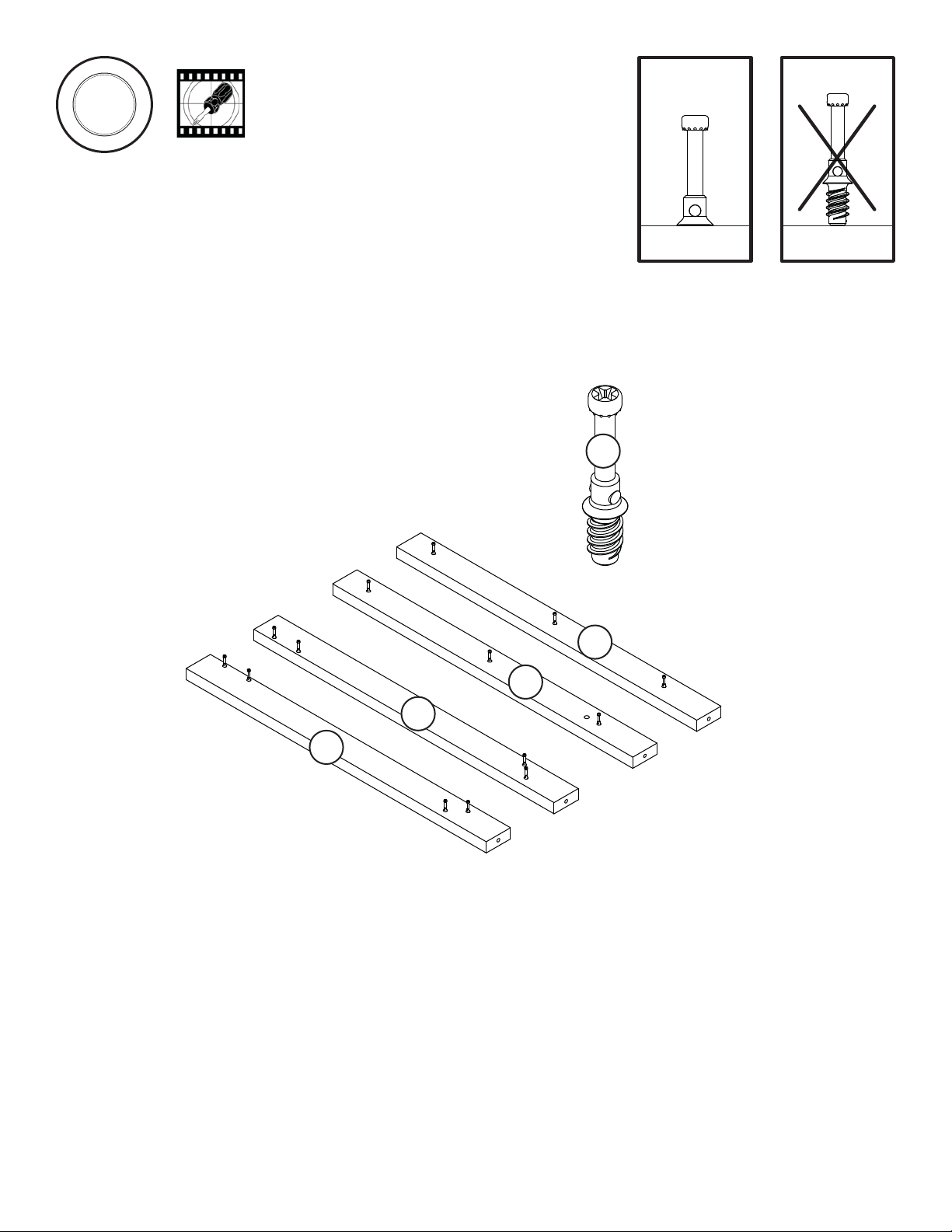
Look for this icon. It means a video
assembly tip is available at:
www.sauder.com/services/tips
1
1
S
t
e
p
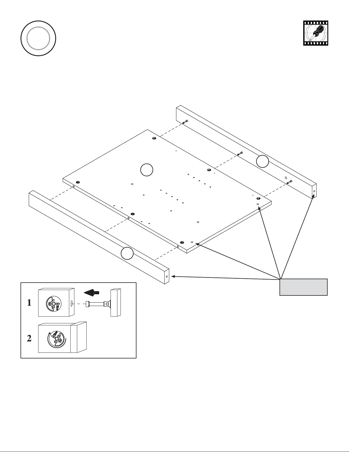
Assemble your unit on a carpeted floor or on the empty carton to avoid scratching your unit or the floor.
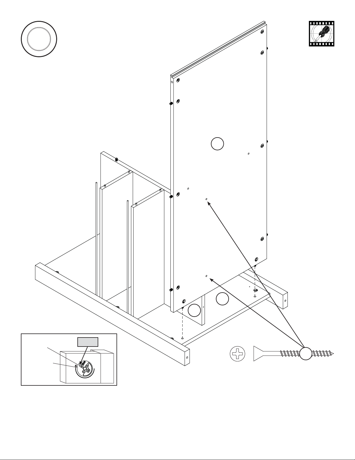
Push twenty-eight HIDDEN CAMS (1F) into the END (A), LOWER UPRIGHT (C), one of the DRAWER UPRIGHTS (E),
BOTTOM (H), SHELF BACK (L), and SHORT BOTTOM MOLDING (U). Then, insert the metal end of a CAM DOWEL (2F) into
each HIDDEN CAM except in the END (A), DRAWER UPRIGHT (E), SHORT BOTTOM MOLDING (U) and the two holes called
out in the BOTTOM (H).
Page 5
www.sauder.com/services414405
Do not tighten the HIDDEN CAMS in this step.
Do not insert
CAM DOWELS
into these holes.
Do not insert CAM
DOWELS into
these edges.
Arrow
(14 used)
(28 used)
Arrow
Arrow
Arrow
1F
1F
1F
1F
1F
1F
1F
2F
2F
2F
2F
Insert the metal end of the CAM
DOWEL into the HIDDEN CAM.
Arrow
Arrow
Arrow
Arrow
A
L
C
H
E
U
2
2
S
t
e
p
Page 6 www.sauder.com/services 414405
Turn fourteen CAM SCREWS (8F) into the LEGS (N, O, P, and Q).
8F
P
Q
N
O
Fasten the RIGHT LEGS (N and Q) to the RIGHT END (A). Tighten six HIDDEN CAMS.
3
3
S
t
e
p
Page 7
www.sauder.com/services414405
N
Q
A
Surface with
HIDDEN CAMS
These holes must
be here.
4
4
S
t
e
p
Page 8 www.sauder.com/services 414405
Surface without
HIDDEN CAMS
L
J
J
13A
Fasten the SHELF BACK (L) to the RIGHT END (A). Tighten two HIDDEN CAMS.
Insert four METAL PINS (1R) into the RIGHT END (A).
Push two SHELVES (J) over the METAL PINS (1R).
Insert four METAL PINS (1R) into the top short edges of the SHELVES (J).
Insert two RODS (13A) into the holes in the RIGHT END (A).
1R
1R
Caution
Risk of damage or
injury. Hidden Cams
must be completely
tightened. Hidden
Cams that are not
completely tightened
may loosen, and parts
may separate.
To completely tighten:
Start Tighten
Arrow
Arrow
Maximum
210 degrees
Minimum
190 degrees
Finished edge
Unfinished surface
A
Edge with two holes
5
5
S
t
e
p
Page 9
www.sauder.com/services414405
Fasten the BOTTOM (H) to the RIGHT END (A). Tighten two HIDDEN CAMS.
Fasten the BOTTOM (H) to the SHELF BACK (L). Use two BLACK 1-7/8" FLAT HEAD SCREWS (2S).
Maximum
210 degrees
Minimum
190 degrees
Arrow
A
H
Surface with
HIDDEN CAMS
BLACK 1-7/8" FLAT HEAD SCREW
(2 used in this step)
2S
L
6
6
S
t
e
p
Page 10 www.sauder.com/services 414405
Maximum
210 degrees
Minimum
190 degrees
Arrow
You will need someone's help in this step.
Fasten the LOWER UPRIGHT (C) to the SHELF BACK (L). Tighten two HIDDEN CAMS.
NOTE: Be sure the PINS and RODS insert into the holes in the LOWER UPRIGHT.
Fasten the BOTTOM (H) to the LOWER UPRIGHT (C). Use two BLACK 1-7/8" FLAT HEAD SCREWS (2S).
C
L
J
J
H
BLACK 1-7/8" FLAT HEAD SCREW
(2 used in this step)
2S
Surface without holes
Edge with CAM DOWELS