Sauder OFFICE WORKS AFFIRM 427869 User manual

sauder.com
NOTE: THIS INSTRUCTION
BOOKLET CONTAINS IMPORTANT
SAFETY INFORMATION.
PLEASE READ AND KEEP FOR
FUTURE REFERENCE.
sauder.com
CONTACT US FIRST
BEFORE MAKING ANY RETURNS TO THE STORE.
sauder.com
CONTACT US FIRST
BEFORE MAKING ANY RETURNS TO THE RETAILER.
Sauder.com
Share your journey!
How can we help you? To reach our customer service, visit sauder.com/commercial-oce/service
to chat with a live rep or email us.
Prefer the phone? Give us a ring at
877-996-7539
.
Our award-winning team is available Monday-Friday - 8:30 a.m. to 5 p.m. EST (except holidays).
Lot # 572574 10/08/21
Purchased: __________________
English pg 1-24
Français pg 25-28
Español pg 29-32
2-Drawer
Mobile Pedestal
Classic Cherry finish | Model 427869
AFFIRM COLLECTION

Table of Contents Assembly Tools Required
Part Identification
Hardware Identification
Hardware Usage Guide
Assembly Steps
Français
Español
Safety
Warranty
Hammer
Not actual size
No. 2 Phillips Screwdriver
Tip Shown Actual Size
3
4
6
5-24
25-28
29-32
33-34
35
Adjustable Wrench
427869 www.sauder.com/commercial-oce/servicePage 2

Part Identification
åWhile not all parts are labeled, some of the parts will have a label or an inked letter on the edge
to help distinguish similar parts from each other. Use this part identification to help identify similar parts.
Now you know
our ABCs.
A RIGHT END (1)
B LEFT END (1)
C TOP (1)
D BACK (1)
D78 DRAWER BACK (2)
D581 RIGHT DRAWER SIDE (2)
D582 LEFT DRAWER SIDE (2)
D707 DRAWER BOTTOM (2)
E BOTTOM (1)
F BASE (1)
G DRAWER FRONT (1)
H LOCKING DRAWER FRONT (1)
A
B
C
D
E
F
H
D78 D581
D707
D582
G
D78 D581
D707
D582
427869www.sauder.com/commercial-oce/service Page 3

Hardware Identification
åScrews are shown actual size. You may receive extra hardware with your unit.
(EXTENSION SET SHOWN SEPARATED)
EXTENSION
SLIDE - 4
40MC
EXTENSION
RAIL - 4
40MA 10A SLIDE
CAM - 4 8B FILE
ROD - 4 15B FILE
GLIDE - 4 8CN NON-SWIVEL
CASTER - 2
8CS SWIVEL
CASTER - 2 42F WOOD DOWEL - 16 4G METAL
BRACKET - 4 34G INTERLOCK
MECHANISM - 1 62G DRAWER
ACTUATOR - 2
76G L - LOCK
BRACKET - 1 77G Z - LOCK
BRACKET - 1 22J LOCK PACK - 1 195K PULL - 2 9M TOUCH-UP PEN - 1
1S BLACK 9/16" LARGE HEAD SCREW - 28 3S GOLD 5/16" FLAT HEAD SCREW - 16
37S BLACK 7/8" MACHINE SCREW - 4 51S BLACK 9/16" PAN HEAD SCREW - 3
30S BLACK 1-9/16" FLAT HEAD SCREW - 8
11S BLACK 1/2" FLAT HEAD SCREW - 6
427869 www.sauder.com/commercial-oce/servicePage 4

Hardware Usage Guide
1. Insert the dowel end of the FASTENER into the
hole of the adjoining part.
NOTE: The dowel end of the FASTENER must
remain fully inserted in the hole of the adjoining
part while locking the FASTENER.
2. Tighten the FASTENER with a Phillips
screwdriver as tight as possible.
Dowel end
2.
Push a TWIST-LOCK® FASTENER
into the large hole in the part.
1.
HOW TO USE A TWIST-LOCK®FASTENER
427869www.sauder.com/commercial-oce/service Page 5

å Assemble your unit on a carpeted floor or on the empty
carton to avoid scratching your unit or the floor.
å Insert two WOOD DOWELS (42F) into the BACK (D).
å NOTE: You may need to gently tap the WOOD DOWEL in
with your hammer.
å Fasten the BOTTOM (E) to the BACK (D). Tighten one
TWIST-LOCK® FASTENER.
å NOTE: Be sure the WOOD DOWELS in the BACK insert
into the BOTTOM.
Step 1 2
D
E
Surface with
TWIST-LOCK®
FASTENERS
Surface with
TWIST-LOCK®
FASTENERS
Just think. The sooner
you do this, the sooner
you do something else.
42F
42F
427869 www.sauder.com/commercial-oce/servicePage 6

Step 2 7
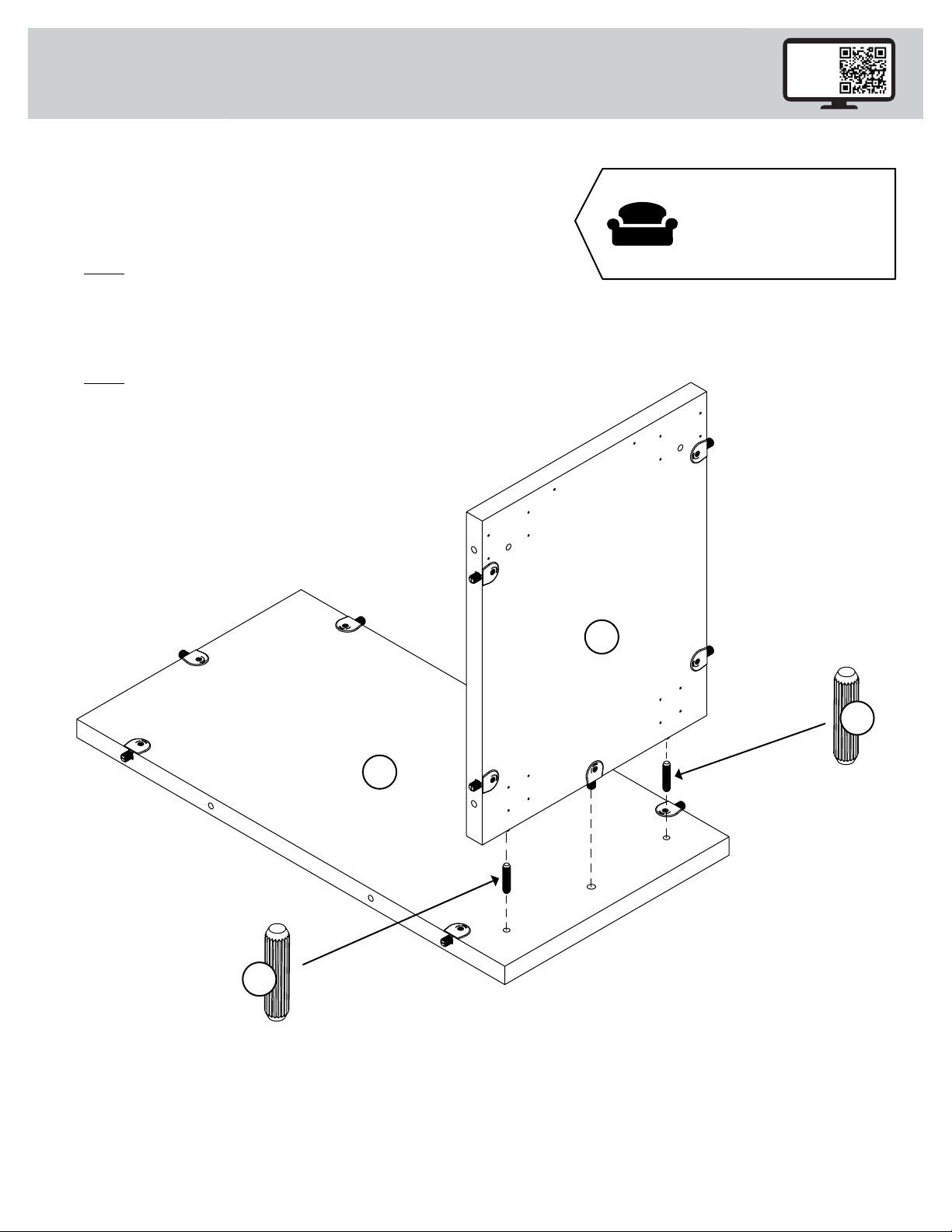
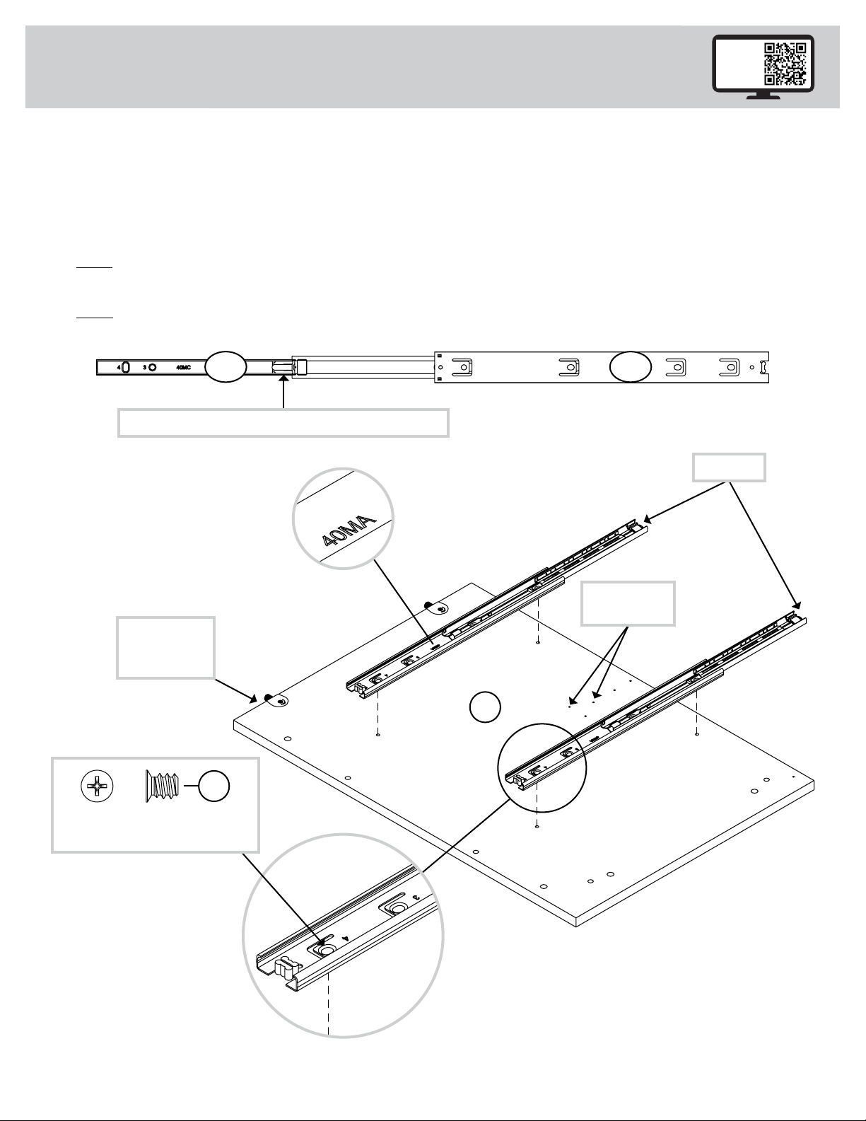
å Separate the EXTENSION SLIDES (40MC) from the EXTENSION RAILS (40MA) as shown in the upper diagram below. Be
prepared, the parts are greasy.
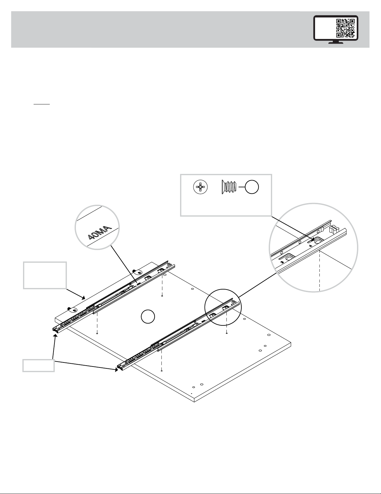
å Fasten two EXTENSION RAILS (40MA) to the RIGHT END (A). Use four GOLD 5/16" FLAT HEAD SCREWS (3S) through
holes #1 and #4.
å NOTE: For each EXTENSION RAIL, turn a SCREW into the hole shown in the enlarged diagram. Then, slide the inner cartridge
of the EXTENSION RAIL in to find the other hole that lines up with the hole in the END. Turn a SCREW into this hole.
å NOTE: The EXTENSION SLIDES will be used later for the DRAWERS.
Push the black lever in and pull the SLIDE from the RAIL.
40MA40MC
1
2
3
4
A
1
2
3
4
Open end
These holes
must be here.
GOLD 5/16" FLAT HEAD SCREW
(4 used in this step)
3S
Edge with
TWIST-LOCK®
FASTENERS
427869www.sauder.com/commercial-oce/service Page 7

Step 3
å Fasten the INTERLOCK MECHANISM (34G) to the RIGHT END (A).
Use three BLACK 9/16" PAN HEAD SCREWS (51S).
å Fasten the L-LOCK BRACKET (76G) to the RIGHT END (A) exactly
as shown. Use two BLACK 9/16" LARGE HEAD SCREWS (1S).
BLACK 9/16" LARGE HEAD SCREW
(2 used for the BRACKET)
1S
A
34G
76G
BLACK 9/16" PAN HEAD SCREW
(3 used for the MECHANISM)
51S
427869 www.sauder.com/commercial-oce/servicePage 8

å Insert four WOOD DOWELS (42F) into the
RIGHT END (A).
å NOTE: You may need to gently tap the WOOD DOWEL
in with your hammer.
å Fasten the BACK (D) and BOTTOM (E) to the RIGHT
END (A). Tighten four TWIST-LOCK® FASTENERS.
å NOTE: Be sure the WOOD DOWELS in the END and
insert into the BACK and BOTTOM.
Step 4
A
2
D
E
42F
(4 used)
427869www.sauder.com/commercial-oce/service Page 9

Step 5 7
3
2
1
4
Open end
å Fasten two EXTENSION RAILS (40MA) to the LEFT END (B).
Use four GOLD 5/16" FLAT HEAD SCREWS (3S) through
holes #1 and #4.
å NOTE: For each EXTENSION RAIL, turn a SCREW into the
hole shown in the enlarged diagram. Then, slide the inner
cartridge of the EXTENSION RAIL in to find the other hole that
lines up with the hole in the END. Turn a SCREW into this hole.
B
3
2
1
4
Edge with
TWIST-LOCK®
FASTENERS
GOLD 5/16" FLAT HEAD SCREW
(4 used in this step)
3S
427869 www.sauder.com/commercial-oce/servicePage 10

Step 6 2
B
D
E
å Insert four WOOD DOWELS (42F) into
the LEFT END (B).
å NOTE: You may need to gently tap the WOOD DOWEL
in with your hammer.
å Fasten the LEFT END (B) to the BACK (D) and
BOTTOM (E). Tighten four TWIST-LOCK® FASTENERS.
å NOTE: Be sure the WOOD DOWELS in the BACK and
BOTTOM insert into the END.
42F
(4 used)
427869www.sauder.com/commercial-oce/service Page 11

å Insert six WOOD DOWELS (42F) into the TOP (C).
å NOTE: You may need to gently tap the WOOD DOWEL in
with your hammer.
å Fasten the ENDS (A and B) and BACK (D) to the
ENDS (A and B). Tighten five TWIST-LOCK® FASTENERS.
å NOTE: Be sure the WOOD DOWELS in the TOP insert into
the ENDS and BACK.
Step 7
A
D
B
C
42F
42F
2
Now might be a
good time to refresh
your drink.
(6 used)
427869 www.sauder.com/commercial-oce/servicePage 12

Step 8
å Fasten four METAL BRACKETS (4G) to the
ENDS (A and B) and BOTTOM (E). Use four
BLACK 9/16" LARGE HEAD SCREWS (1S).
å NOTE: Be sure the BRACKETS are even with the edges of
the ENDS and BOTTOM.
å Fasten the BASE (F) to the METAL BRACKETS on the
ENDS and BOTTOM. Use four BLACK 9/16" LARGE
HEAD SCREWS (1S).
4G
BLACK 9/16" LARGE HEAD SCREW
(8 used in this step)
1S
4G
4G
A
B
E
F
Edge with
wrapped seam
427869www.sauder.com/commercial-oce/service Page 13

å Fasten the CASTERS (8CN and 8CS) to the BOTTOM (E)
exactly as shown. Use sixteen BLACK 9/16" LARGE
HEAD SCREWS (1S).
Step 9
BLACK 9/16" LARGE HEAD SCREW
(16 used in this step)
1S
E
8CN
8CS
The small tab
should be here.
427869 www.sauder.com/commercial-oce/servicePage 14

å Fasten the Z-LOCK BRACKET (77G) to the
DRAWER FRONT (G). Use two BLACK 9/16"
LARGE HEAD SCREWS (1S).
Step 10
BLACK 9/16" LARGE HEAD SCREW
(2 used in this step)
1S
G
77G
427869www.sauder.com/commercial-oce/service Page 15

Step 11
With the palm of
your hand, tap
the DRAWER
BOTTOM down
into the groove.
å Fasten the DRAWER BACK (D78) to the DRAWER SIDES (D581 and D582). Use four BLACK 1-9/16"
FLAT HEAD SCREWS (30S).
å NOTE: Be sure the DRAWER BOTTOM (D707) inserts into the groove of the DRAWER BACK (D78).
å Repeat this step for the other drawer.
1 2
3
å Insert the DRAWER SIDES (D581 and D582) at an angle
into the slot at each end of the DRAWER FRONT (G). å Slide the DRAWER BOTTOM (D707) into the grooves
in the DRAWER SIDES (D581 and D582) and
DRAWER FRONT (G).
The tabs should insert freely
into the slots. Gently tilt the
DRAWER SIDES side to side
until the tabs slip into the slots.
Groove
30S
Start each screw a few turns before
completely tightening any of them.
BLACK 1-9/16" FLAT HEAD SCREW
(8 used in this step)
Be sure the DRAWER
BOTTOM inserts into the
DRAWER FRONT groove.
G
D707
D707
D78
Unfinished
surface
Be sure the
DRAWER
BOTTOM
inserts into
the DRAWER
BACK groove.
9
D582
D581 D582
D581
G
D582
D581
427869 www.sauder.com/commercial-oce/servicePage 16

Step 12
å Insert a SLIDE CAM (10A) into each DRAWER SIDE (D581 and D582).
å Fasten the EXTENSION SLIDES (40MC) to the DRAWER SIDES (D581 and D582). Use four
GOLD 5/16" FLAT HEAD SCREWS (3S) through holes #1 and #4.
å NOTE: The screw head in the CAM must be visible through the slotted hole in the SLIDE.
å Repeat this step for the other drawer.
Open end 10A
Open end
GOLD 5/16" FLAT HEAD SCREW
(8 used in this step)
3S Drawer Slide
Center the screw in the oval hole.
1
2
3
4
1
2
3
4
Screw head - turn CAM to line up holes in
the SLIDES with holes in DRAWER SIDES
10A
D582
D581
7
427869www.sauder.com/commercial-oce/service Page 17

å Fasten one PULL (195K) to the DRAWER FRONT (G). Use
two BLACK 7/8" MACHINE SCREWS (37S).
å Repeat this step for the other drawer.
Step 13
G
195K
BLACK 7/8" MACHINE SCREW
(4 used in this step)
37S
427869 www.sauder.com/commercial-oce/servicePage 18

å Fasten one DRAWER ACTUATOR (62G) to the RIGHT DRAWER
SIDE (D581) of the LOCKING DRAWER FRONT (H) exactly as
shown. Use three BLACK 1/2" FLAT HEAD SCREWS (11S).
å Fasten one DRAWER ACTUATOR (62G) to the RIGHT DRAWER
SIDE (D581) of the DRAWER FRONT (G) exactly as shown. Use
three BLACK 1/2" FLAT HEAD SCREWS (11S).
Step 14
H
G
D581
D581
This DRAWER ACTUATOR
is closer to hole in the
LOCKING DRAWER FRONT.
This DRAWER ACTUATOR is
closer to the bottom edge of
the DRAWER SIDE.
62G
BLACK 1/2" FLAT HEAD SCREW
(6 used in this step)
11S
427869www.sauder.com/commercial-oce/service Page 19

Step 15
å Push a FILE GLIDE (15B) onto the RIGHT DRAWER SIDE (D581).
å Slide the FILE RODS (8B) into the FILE GLIDE (15B) on the RIGHT
DRAWER SIDE.
å Slide another FILE GLIDE (15B) onto the other end of the FILE RODS (8B),
then press this FILE GLIDE over the LEFT DRAWER SIDE (D582).
å Repeat this step for the other drawer.
Insert the FILE RODS into the holes
of your choice in the FILE GLIDES,
depending on your file sizes.
D582
D581
8B
15B
15B 8B
427869 www.sauder.com/commercial-oce/servicePage 20
This manual suits for next models
1
Table of contents
Languages:
Other Sauder Storage manuals
Popular Storage manuals by other brands

Adaptec
Adaptec 29320LPE - SCSI Card Storage Controller U320 320... datasheet

Fujitsu
Fujitsu M2301B manual

Seagate
Seagate ST34555N product manual

Kingston Technology
Kingston Technology DataTraveler 4000 user manual

LaCie
LaCie DataShare datasheet

Huawei
Huawei OceanStor CloudStor CSE Quick installation guide