Yamatake CY8000C User manual

AB-5798
1
Insert Type CO2Concentration Transmitter
CY8000C
General
The CY8000C insert type CO2concentration transmitter
detects the concentration of carbon dioxide (CO2) in ducts
and other test sites. The CY8000C can be used in a
wide range of applications such as monitoring of CO2
concentration in retain ducts and the control of outdoor air
intake.
Features
1) Non-dispersive infrared absorption method (NDIR)
2) Linear output signal in 1 to 5 VDC range
3) Stability over prolonged use
Model
Model No. Description
CY8000C1000 Insert Type CO2Concentration
Transmitter
Specifications
Item Specifications
Sensing range CO2Concentration 0 to 2000 ppm
Sensing element Non-dispersive infrared absorption
method (NDIR)
Sensing accuracy ± (50 ppm + 5 % of readout)
Time constant 2 min or less (non-wind state)
10 s or less (when air velocity is 2 m/s)
Operating
environmental
conditions
CO2Concentration: 0 to 2000 ppm
Temperature: 0 to 50 °C
Humidity: 0 to 95 % RH
(no condensation)
Transport/storage
conditions
Temperature: 0 to 50 °C
Humidity: 0 to 95 % RH
(moisture-proof, packed)
Power supply
voltage
24 VAC ± 10 % (50 to 60 Hz)
Power
consumption
0.4 VA
Output signal 1 to 5 VDC (CO2concentration 0 to 2000
ppm linear)
Allowable load
resistance
500 Ωor more
Wiring Power supply 2P, CO2concentration
output 2P
Initial stabilizing
time
Within 1 m
Allowable vibration 4.9 m/s² (10 to 150 Hz)
Insulating
resistance
100 M or more at 500 VDC
(across bobbin and leads)
Item Specifications
Insulation
withstand voltage
Leakage current of 1 mA or less for
1 minute at 500 VAC
(across bobbin and leads)
Weight Approx. 540 g
Finish Bobbin: Aluminum
Case: Polycarbonate
Cover: Polystyrene
Mounting Duct, chamber
Specifications/Instructions

2 AB-5798
Optional accessories
Description Quantity
Mounting bracket 1 (w/ 2 screws)
Rubber packing 1
Procurement item
Model No. Description
83104511-001 CO2 service bag (CO2zero gas supply kit)
Dimensions (mm)
Safety Instructions
Please read instructions carefully and use the product properly. Please keep this instruction on hand for reference at
any time.
Usage Restrictions
This product is targeted for general air conditioning. Do not use this product in a situation where human life may be
affected. If this product is used in clean rooms or places where reliability or control accuracy is particularly required,
please contact Yamatake’s sales representatives. Yamatake Building Systems Co., Ltd. bears no responsibility for
any benefit, or lack of benefit, derived from the operation by the customer.
WARNING
●Disconnect the power supply before beginning wiring to prevent electrical shock or equipment damage.
●Do not remove or disassemble the cover except for wiring or part replacement. Equipment damage or
electrical shock may result.
●Check for loose wiring to prevent heat generation or equipment damage.
●Use insulated terminals.
●In a space where fresh air is always required, or in harsh environments where more fresh air than usual is
required, control of fresh air (outdoor air) intake involves risks. Do not control fresh air (outdoor air) intake
using CO2measuring instruments, including this product, under such conditions.
CAUTION
●Installer must be a trained, experienced technician.
●Check the ratings given in this insstructions to prevent equipment damage.
●Check the environment given in this instructions to prevent equipment damage.
●All wiring must confirm to local codes and ordinances.
MO4347b
26 42
14
Φ5.5
54
75
3
φ5.5
54
20
φ6.1
180
55 230
94

3 AB-5798
Installation
Precautions Upon Installation
1. Select and install the CO2concentration transmitter at a
location where it can detect typical concentrations of
CO2in test gases and where the required air velocity
can be ensured.
2. Insert the CO2concentration transmitter so that all of
the holes on the insert (bobbin) section are in the duct
(containing the test gas), and install so that the
direction of air flow matches the "→" on the cover.
3. We recommend using connectors for wiring to simplify
maintenance, inspection and calibration.
Installation
1. Prepare the exclusive mounting bracket. Cut out a 30
mm dia. hole at the position where the CO2
concentration transmitter is to be installed.
2. Fasten the mounting bracket and packing with the
screws provided.
3. ①Insert the bobbin into the bracket taking care to
insert it up to the topmost ventilation hole (hole closest
to the case).
②Tighten the bracket neck screws.
Lead Color Item
White 24 VAC
Brown 24 VAC
Green Output (-) common
Yellow Output (+) 1 to 5 VDC
When a Separate Transformer Is Used
CAUTION
●Use an insulated transformer to supply 24
VAC power supply voltage.
Never share the 24 VAC power supply with
other equipment.
If a transformer is shared with other
equipment, a loop will be formed at common
and the transmitter may be damaged.
•Transformer shared
+
Duct
Direction of
air flow
②Tighten after
inserting
transmitter.
①Insert
CO2 concentration transmitter
Align arrow with direction
of air flow.
Packing
24V AC +
-
~
⊥ ⊥
Multi-loop
controller
CO2concentration
transmitter
Y+
-
~
⊥ ⊥
CO2concentration
transmitter Shared
common
line
Common loop formed
×NO GOOD

4 AB-5798
•Separate transformer
Operation check
Make sure that only the green LED starts blinking within
one minute of the power turning ON.
(During normal operation, only the green LED blinks.)
Maintenance
Periodic Calibration
We recommend calibrating the transmitter once every
year. However, determine the calibration period
according to the amount of dust or dirt in the test gas.
Calibration
1. Initial Calibration
The CO2concentration transmitter is inspected and
adjusted before it is shipped from the factory. So, it
does not need to be adjusted at the installation
site.
2. Periodic Inspection
We recommend inspecting inside the case (circuit
boards, etc.) of the CO2concentration transmitter as
test gas enters the case.
Calibration Method
The separate CO2Service Bag (procurement item No.:
83104511-001) is needed for calibrating the transmitter.
1. Remove the cover from the CO2concentration
transmitter.
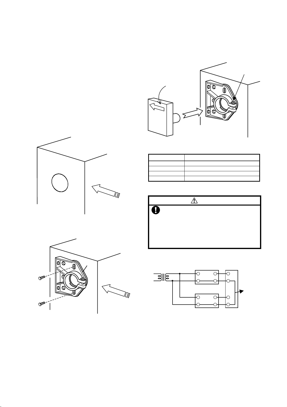
2. Insert the inlet (tube tip) of the CO2Service Bag into the
CO2concentration zero gas inlet as shown in the figure
at the bottom right.
3. Turn the CO2service bag ON to start supply of CO2
concentration zero gas to the CO2concentration
transmitter.
4. With the zero gas still supplied, wait for the CO2
concentration to stabilize. (Generally, this takes about
five minutes.)
5. When CO2concentration has stabilized, calibrate the
CO2concentration transmitter. (zero adjustment
completion method using buttons)
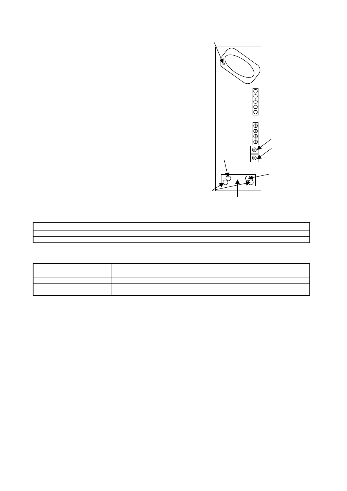
1) Simultaneously hold down the (+) and (-) buttons on
the circuit board. Hold these buttons down for
about five seconds until the yellow and red LEDs
light. This sets the CO2concentration transmitter to
the service mode. (In this state, the CO2
concentration and "OP1" are displayed alternately
on the LCD panel.)
2) Press the (+) once. The LCD panel display changes
to indicate the CO2concentration and "OP2". This
indicates that the calibration menu is entered. If
"OP2" is not displayed, press the (+) key again until
"OP2" is displayed.
3) Hold down the (-) button for about three seconds
until all LEDs (green, yellow, red) light. This starts
calibration. All LEDs light when calibration begins
and go out when calibration ends. When all LEDs
go out, this indicates that the CO2concentration
transmitter has returned to the standard
measurement mode.
IMPORTANT:
Press the (-) button at only OP2. Do not
press this button at other menu items. (If you
press the (-) button at different menu item, the
functions of the CO2concentration transmitter
are sometimes adversely affected. If you have
executed a different menu item, contact a
Yamatake service engineer.)
6. Tighten the cover of the CO2concentration transmitter.
(During this operation, do not mistake the top and
bottom of the cover. (If you do so, the arrow will face
the opposite direction.))
To return to the user mode from the service mode
without calibrating the CO2concentration transmitter,
repeatedly press the (+) button to advance the service
mode one menu item at a time. Advance the mode
"OP1" →"OP2" →"OP3" →"OP4" →"OP5" →
"OP6" →and press the (+) button again to return to the
user mode.
Y
24 VAC +
-
~
⊥ ⊥
Multi-loop
controller
Y+
-
~
⊥ ⊥
24 VAC
○GOOD
No common loop formed

5 AB-5798
Reference) About the Service Mode Menu
The Service Mode has six service menu items: OP1 to
OP6. However, only menu item OP2 is used in this
calibration.
OP2: Calibration menu
This operation involves calibrating the zero level of
the CO2concentration transmitter. When this
operation is executed, calibration is performed so that
the CO2concentration measured on the transmitter at
this time is taken as zero. When you execute this
operation, be sure to follow the above calibration
method.
*If you hold down the (-) button in the service mode for about
three seconds, that service mode menu item (see reference
page) is executed. (All LEDs (green, yellow, red) light.)
Do not execute menu items other than OP2.
Explanation of Pushbuttons
Button Description
(+) Button Used to enter the service mode, and to advance the menu item in the service mode.
(-) Button Used to enter the service mode, and execute the operation in the service mode.
Explanation of LEDs
Standard mode Service mode
Green LED Blinks during normal operation Same as standard mode
Yellow LED Lights when an error occurs. Lights when the service mode is entered.
Red LED Lights when the output range is exceeded. Lights during execution of a service mode
menu item.
CO2concentration zero gas inlet
+
-
(+) button
(-) button
Yellow LED
Red LED
Green LED
LCD panel

6 AB-5798
Building Systems Company
International Business Headquarters
Totate International Building
1-12-19, Shibuya
Shibuya-Ku,Tokyo, 150-8316
URL:http//www.yamatake.com
Rev.1.0 Dec. 2000 Printed in Japan. AB-5798 0.5H-H (W)
Specifications are subject to change without notice.
This manual suits for next models
1
Table of contents
Other Yamatake Transmitter manuals