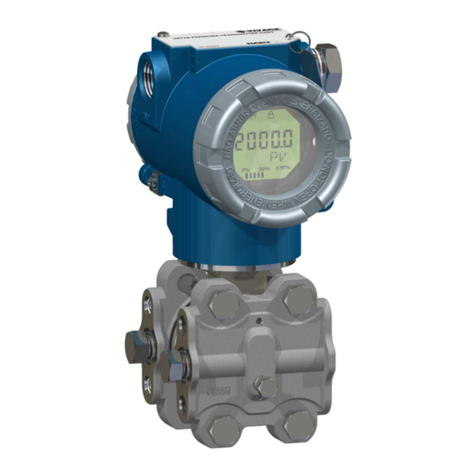
HART HK51 User manual

Monocrystalline Silicon Smart Pressure
Transmitter Operation Manual
®
HK51 HK55

Monocrystalline Silicon High Stability Transmitter
3
Thank you very much for purchasing our company's monocrystalline silicon
transmitter products.
This manual provides a detailed introduction to the functions, wiring methods,
setting methods, operating methods, and troubleshooting methods that can
be implemented by the instrument. Before the instrument is put into operation,
it is necessary to read this manual in detail and conduct specific operation
after mastering correct usage method to avoid unnecessary losses caused by
incorrect operation.
◆ Please read this manual carefully before using the instrument. The instrument
can be installed, operated and maintained on premise of full understanding.
Incorrect installation or operation may result in damage to the instrument or
personal injury.
◆ The company promises there is no defects in materials and manufacturing
processes in hardware and accessories that shall be provided when instrument
is supplied. Starting from the date of purchase, the company will carry out
unconditional free maintenance or free replacement for products that are
indeed defective within the one-year warranty period if the company receives
notification of such defects from users. The company guarantees lifetime
maintenance for all products.
◆ In order to comply with the principle of sustainable development, the company
reserves rights to modify performance parameters described in this manual
without prior notice. The company also reserves rights to amend or revoke
this manual without prior notice. When modification of certain performance
parameters of the instrument may result in serious accidents, the company shall
inform users in advance. The company will have a new version of instruction
manual or improvement instruction for modiÞed instrument. If the description
in this manual is inconsistent with the actual product, please refer to the actual
product.
◆ It is strictly forbidden to make any modification to the instrument! The
company is not responsible for accidents caused by unauthorized modiÞcation
of this product.
Preface

4
Content
1. Document information ·············································································· 05
1.1 Document function ··················································································· 05
1.2 Chart ············································································································ 05
1.3 Electric chart ······························································································ 05
2. Basic safety instruction ·············································································· 06
2.1 Personnel requirement ············································································ 06
2.2 Misuse ········································································································· 06
2.3 Safety of working location ····································································· 06
2.4 Operational safety ··················································································· 06
2.5 Dangerous zone ······················································································· 07
2.6 Product safety ·························································································· 07
2.7 Functional safety (optional) ··································································· 07
3. Product performance description ·························································· 08
3.1Characteristics ····························································································· 08
3.2 Dimension Þgure ······················································································ 10
4. Installation ···································································································· 12
4.1Conventional installation instruction ····················································· 12
4.2 On-site installation ··················································································· 12
4.3 Installation location ·················································································· 13
4.4 Installation in dangerous places ··························································· 13
4.5 Notes for using explosive-proof transmitter ····································· 14
4.6 Measurement method ············································································ 15
5.Wiring ············································································································· 17
5.1 Wiring device ····························································································· 17
5.2 Wiring method ························································································· 17
6. Debugging ··································································································· 19
6.1 Local three-button debugging ······························································ 19
7.Maintenance and troubleshooting of transmitter ······························· 21
7.1 Instrument maintenance ········································································· 21
7.2 Troubleshooting ························································································ 21
7.3 Display of error code ··············································································· 22
Monocrystalline Silicon High Stability Transmitter

5
1. Document information
1.1 Document function
The document contains all the information required at different stages of the
equipment life cycle: from product identication, arrival acceptance and storage,
to installation, electrical connection and commissioning, and troubleshooting,
maintenance and disposal.
1.2 Icon
Icon Description
Danger Danger!
Dangerous status alert icon.
Negligence will result in serious or fatal injury.
Warning Warning!
Dangerous status alert icon.
Negligence will result in serious or fatal injury.
Be careful Be careful!
Dangerous status alert icon.
Negligence will result in serious or fatal injury.
Attention Attention!
Alert information icons of operation and other effects.
Does not cause personal injury.
1.3 Electric icon
Icon Description Icon Description
DC AC
DC and AC Ground connection
The operator recognizes
by default that this ground
terminal has been reliably
grounded through the
grounding system.
Before the protective
ground connection is
made for subsequent
electrical connections,
it shall ensure that the
terminal is grounded
safely and reliably.
Equipotential connection
It shall be connected to the
factory grounding system:
Use an equipotential
bonding cable or a
star grounding system
connection, depending
on national standards or
company speciÞcations.
Monocrystalline Silicon High Stability Transmitter

6
2. Basic safety guidelines
2.1 Personnel requirements
Personnel performing installation, commissioning, diagnostics and maintenance
operations shall meet the following requirements:
◆ Trained and qualied professionals shall have qualication to perform specic
operations and tasks
◆ Authorized by the factory/operator
◆ Familiar with alliance / national regulations
◆ Professionals shall read and understand this Operating Instructions,
supplementary documents and certiÞcates before operation.
◆ Follow the operating guidelines and basic conditions
The operator shall meet the following requirements:
◆ Guided and authorized by the company according to mission requirements
◆ Follow the guidelines in this Operating Instructions
2.2 Error description
The manufacturer is not responsible for damage caused by improper use or
non-designated use.
Verifying measurement conditions:
When measuring special fluids and cleaning fluids, the company is pleasant
to help verify the corrosion resistance of fluid connection parts, but do not
guarantee or assume any responsibility.
2.3 Workplace safety
When operating equipment:
◆ Compliance with alliance / national regulations, personnel shall wear protective
equipment.
◆ Turn off the power before wiring the device.
2.4 Operation safety
There is a risk of personal injury!
▲ Operate the equipment only under correct technical conditions and
guaranteed safety conditions.
▲ It is the responsibility of the operator to ensure the equipment is operated
without interference.
Modication of equipment
Unauthorized equipment changes are prohibited, which may result in unforeseen
dangers:
▲ If changes are necessary, please consult our local sales center.
Repair
▲ Ensure operational safety and reliability.
▲ Only devices that are explicitly allowed:
▲ Only use original spare parts and accessories from our company.
Monocrystalline Silicon High Stability Transmitter

7
2.5 Hazardous area
When the equipment is used in a hazardous area, measures shall be taken to
eliminate the danger of personnel or equipment (e.g. explosion protection,
pressure vessel safety):
◆ Refer to the nameplate to check and conrm that the ordered equipment is
allowed to be used in a hazardous area.
◆ Comply with provisions in the supplemental documents, which is part of the
Operation Manual.
2.6 Product safety
Measuring equipment is designed based on engineering practice and meets
the most advanced and stringent safety requirements. It is safe to use through
factory testing. The measuring equipment meets general safety requirements
and legal requirements. It also meets requirements of the CE Directive in
the Equipment CE Declaration of Conformity. The company ensures that the
measuring equipment with CE mark complies with this requirement.
2.7 Functional safety (optional)
When using the device in an application with overall safety requirements, it is
necessary to fully comply with requirements of Usage Instructions.
Monocrystalline Silicon High Stability Transmitter

8
3. Product performance description
3.1 Features
(1) High accuracy
The differential pressure (ßow) transmitter can measure high accuracy within the
measurement range of 0.1~40000kPa. Migration of positive and negative zero
point is not necessary for linearity adjustment.
(2) Excellent environmental adaptability
Smart static pressure compensation and temperature compensation protect the
transmitter from effects of temperature, static pressure and overpressure, and
minimize on-site comprehensive measurement error.
(3) Flexible range compression
◆ Micro range (0...6kPa) ratio: 3:1
◆ Medium range ratio: 10:1
◆ Maximum range ratio: 10:1
(4) Excellent operability and ease of use
◆ 5 digits with backlit LCD digital display
◆ Multiple display functions (Pa, kPa, MPa, %, psi)
◆ Built-in three-button shortcut operation in-place adjustment function
◆ Available in various anti-corrosion materials
◆ Comprehensive self-diagnosis function
Monocrystalline Silicon High Stability Transmitter

9
◆ Output signal: DC4~20mA+HART protocol
◆ Allowable load resistance: 0~600Ω (when DC 24V)
Note: A standard (250 Ω) load resistor is required to communicate with the
handheld communicator.
◆ Power supply:
General purpose DC10.5~45V
Intrinsically safe explosion-proof DC10.5~26V
◆ Communication line conditions: Line length: up to 2km (0.75~1.25mm2 control
instrument cable, use twisted pair cable for more than 1km)
Load resistance: 250~600Ω
(DC 24V, including cable resistance)
Load capacitance: below 0.55mF
Load inductance: 3.3mH with power line spacing: 15cm or more
(Please avoid parallel wiring)
◆ Saturation current: upper limit 20.8mA
Lower limit 3.8mA
◆ Alarm current: upper limit 22.8mA
Lower limit 3.6mA
◆ Adjustment function: Zero point and full-scale point can be adjusted on site
from the top three buttons of the outer casing or can be adjusted remotely by
using conÞguration software.
◆ Zero migration: Can migrate within the range of -20% to +20% of the
maximum range
◆ Output mode: linear output
Square root output
(May achieve remote adjustment via conÞguration software)
◆ Ambient temperature: -40~+85° C
(When lling with uorine oil: -10~+60° C)
◆ Storage temperature: -40~+90° C
◆ Weather resistance: DIN40040GPC
◆ EMC applicable standard: EN1326-1:2006
Monocrystalline Silicon High Stability Transmitter
10
◆ Square root output accuracy
Output Accuracy
≥50% Same as the reference accuracy
50%~Dropping point Reference accuracy x 50
Square root output (%)
◆ Power supply impact: ±0.005%/1V
◆ Installation position influence: Installation position changes in the direction
parallel to the diaphragm will not cause zero drift. If the installation position and
the diaphragm surface change by more than 90° , zero drift within the range of
0.4KPa can be corrected by zero adjustment.
◆ Response time: 90ms
◆ Damping: Time constant can be adjusted within 0~99.9 seconds
◆ Filter constant: Can be adjusted within 0~160uA
◆ Self-stability factor: Can be adjusted within 0~2%
3.2 Dimensional drawing
Differential pressure / splint pressure transmitter
Monocrystalline Silicon High Stability Transmitter

11
Pressure transmitter
Monocrystalline Silicon High Stability Transmitter

12
4. Installation
4.1 General installation instructions
◆ Installation may cause deviations in measured values. For example, when
measuring in an empty container, the measured value displayed is not 0. Zero
shift correction can be performed by local three buttons or by remote operation.
◆ For general installation requirements of pressure pipe, please refer to the DIN
19210 standard "Fluid Measurement Method"; “differential pressure pipeline of
ow measurement equipment”, or related national or international standards.
Easy to commission, install and maintain the instrument with a three-valve or
Þve-valve set without interrupting the process.
◆ When installing the pressure pipe outdoors, take adequate anti-freezing
protection measures, such as pipe heating.
◆ Inclining installation angle of the pressure pipeline shall be at least 10%.
◆ Do not use hard or sharp objects to clean or touch the diaphragm seal.
◆ The maximum rotation angle of housing is 380° to ensure the best readability
of the Þeld display unit.
◆ The live display can be rotated by 90° .
◆ The company provides right angle or flat mounting brackets for the
instrument.
4.2 On-site installation
The smart transmitters produced by our company can be installed directly on
the pipeline or directly on the wall and on the instrument panel. The figure
below shows different installation forms (user selectable).
Differential pressure transmitter
Diagram of installation using a right angle bracket Diagram of installation using a plate bracket
Pressure transmitter
Monocrystalline Silicon High Stability Transmitter

13
4.3 Mounting position
The correct mounting position of the transmitter on the process pipeline is
related to the medium being tested. Note the following conditions in order to
achieve the best installation effect:
◆ Prevent the transmitter from contacting with corrosive or overheated media
under test.
◆ Prevent dross from depositing in the pressure pipe.
◆ The pressure pipe shall be as short as possible.
◆ The liquid column indenter in the pressure pipe on both sides shall be
balanced.
◆ The pressure pipe shall be installed in a place with small temperature gradient
and temperature ßuctuation.
◆ Prevent crystallization or low temperature icing in the pressure pipe.
4.4 Installation in hazardous locations
Smart explosion-proof transmitters shall be used in hazardous locations, and
smart explosion-proof transmitters are extensions of smart transmitters. The
working principle and basic structure are the same as the smart transmitter.
Smart explosion-proof transmitters are available in intrinsically safe and
explosion-proof versions. Explosion-proof and intrinsically safe instruments
comply with provisions of GB3836.1-2000 General Requirements for Explosion-
proof Electrical Equipment in Explosive Atmosphere.
The internal cavity of smart explosion-proof transmitter type can withstand an
explosion, and the internal explosion does not cause explosion of the externally
specified explosive mixture. Mark d conforms to GB3836.2-2000 Explosion-
proof Electrical Equipment Explosion-proof Electrical Equipment. "d" in Explosive
Atmosphere, the explosion-proof grade is ExdIICT6.
Smart - Transmitter intrinsically safe type: refers to the circuit system, the point
spark and thermal effects generated under normal working or specified fault
conditions can not ignite the speciÞed explosive mixture, the mark ia conforms
to GB3836.4-2000 Electrical Equipment Intrinsically Safe Type “i” in Explosive
Atmosphere, the explosion-proof grade is Exia IICT6. The transmitter is used in
conjunction with an associated equipment safety barrier installed in the control
chamber to form an intrinsically safe explosion-proof system.
Monocrystalline Silicon High Stability Transmitter

14
Explosion-proof structure:
The electrical components and circuit boards of all explosion-proof smart
transmitters are placed inside the explosion-proof housing. Even if the
instrument produces a spark internal explosion due to a fault, the transmitter
housing has sufÞcient mechanical strength and ßameproof performance. It not
only does not damage the explosion-proof enclosure, also does not explode
explosive mixtures outside the enclosure.
4.5 Notes for users of explosion-proof transmitters
Smart transmitter explosion-proof products are inspected by the national
instrumentation explosion-proof safety supervision and inspection station
(NEPSI), conforming to requirements specified in GB3836.1-2000, GB3836.2-
2000 and GB3836.4-2000 standards, the product explosion-proof mark is
ExdIICT6 (without acetylene) and ExiaIICT6; users shall pay attention to the
following matters when using the product:
◆ Users of the transmitter housing shall be grounded reliably when in use;
◆ Explosion-proof products are used in an ambient temperature ranging from
-20 ° C to +60 ° C;
◆ Explosion-proof products are used on site, and observe the principle of “open
the cover after power off” during maintenance;
◆ Intrinsically safe products shall be matched with safety barriers LB987S,
MTL787S, E787 etc. recognized by the explosion-proof inspection agency when
installed on site to constitute an intrinsically safe explosion-proof system. In order
to install with other types of safety barriers, it is necessary to obtain approval
from an explosion-proof inspection agency;
◆ Connection cable between the transmitter and the safety barrier's intrinsic end
is a two-core shielded cable (the cable shall have a cable sheath). The cross-
sectional area of the core wire is ≥ 0.5mm2, and the shielding layer is grounded
at a single end in a safe place and insulated from the product casing; the cable
wiring shall eliminate influence of electromagnetic interference as much as
possible, and cable distribution parameter shall be controlled within 0.06μF/1mH.
◆ The safety barrier shall be installed in a safe place. The installation, use and
maintenance shall comply with the safety barrier instruction manual.
Ex d IIC T6
Temperature group
Explosive mixture grade II C
Explosion-proof
Explosion-proof mar k
Ex ia IIC T6
Intrinsically safe
Temperature group
Explosive mixture grade II C
Explosion-proof mark
Monocrystalline Silicon High Stability Transmitter

15
◆ Users are not allowed to change the electrical components and system
matching status of the product at will.
◆ The installation, use and maintenance of the product shall also comply
with the product manual GB3806.15-2000 "Electrical Equipment for Explosive
Gas Atmosphere” Part 15: Electrical installation in hazardous areas (mineral
removal)" and relevant provisions in GB50058-1992 "Electric Equipment Design
Specication in Explosion and Fire Hazard Environment”.
◆ Lead-in cable of the flameproof product shall meet requirements of φ8 ~
φ8.5mm. Tighten the compression nut during on-site use to make the seal ring
hold the cable tightly.
◆ The product has a redundant inlet, which shall be blocked with the plug
provided by our company.
4.6 Measurement method
◆ Liquid measurement:
When measuring ow rate of the liquid, the pressure tap shall be open on the
side of the process pipeline to avoid dross sedimentation. At the same time,
the transmitter shall be installed beside or below the pressure tap to allow air
bubbles to escape into the process pipeline.
◆ Gas measurement:
When measuring gas flow, the pressure tap shall be open at the top or side
of the process pipeline. And the transmitter shall be placed beside or above
the process piping so that accumulated liquid can easily ow into the process
pipeline.
◆ Steam measurement: When measuring steam ow, the pressure port is open
on the side of the process pipeline, and the transmitter is installed under the
pressure port so that the condensate can be Þlled in the pressure pipe.
It shall be noted that when measuring steam or other high temperature media,
the temperature shall not exceed temperature limit of the transmitter.
When medium to be measured is steam, the pressure pipe should be Þlled with
water to prevent the steam from directly contacting the transmitter. Since volume
change of the transmitter is negligible during operation, there is no need to
install a condensing tank.
Note: A transmitter with release valve is equipped in the pressure
chamber and pressure tapping shall be open on the side of the process
pipeline. When the measured medium is liquid, discharge valve of the
transmitter shall be installed to discharge gas that has penetrated in the
measured medium. When measured medium is gas, discharge valve of
the transmitter shall be installed below to discharge accumulated liquid.
Monocrystalline Silicon High Stability Transmitter

16
◆ Level measurement: The differential pressure transmitter used to measure
liquid level is actually the static head for measuring liquid column. This pressure
is determined by the level and specific gravity of liquid. The size is equal to
liquid level above the pressure tap multiplied by specific gravity of the liquid,
regardless of volume or shape of the container.
(a) Level measurement of open container
When measuring liquid level of open container, the transmitter is placed close
to bottom of the container to measure pressure corresponding to the liquid
level above it. Pressure at the tank level is connected to the high-pressure side
of the transmitter and the low-pressure side is open to the atmosphere. If the
lowest level of measured level changes is above the transmitter installation, the
transmitter shall be positively migrated.
(b) Level measurement of closed container
In a closed container, pressure of the container above the liquid affects pressure
at bottom of the container. Therefore, pressure at bottom of the container is
equal to liquid level multiplied by specic gravity of the liquid plus pressure of
the closed container.
In order to measure true level, pressure of the container shall be subtracted from
the measured bottom pressure of the container. Thus, open pressures tap on top
of the container and connect to the low-pressure side of the transmitter so that
the pressure in the container acts on both the high and low-pressure side of the
transmitter. As a result, differential pressure obtained is proportional to product
of the liquid level and specic gravity of the liquid.
◆ Dry pressure connection
If the gas above the liquid does not condense, the connection pipe on the low-
pressure side of the transmitter will remain dry. This condition is called a dry
pressure connection.
The method of determining measurement range of the transmitter is the same
as the method of open container liquid level.
◆ Wet pressure connection
If the gas on the liquid condenses, the liquid will gradually accumulate in the
pressure pipe on the low-pressure side of the transmitter, which will cause
measurement error. In order to eliminate this error, a certain liquid is previously
Þlled in the low-pressure side of the transmitter, which is called a wet pressure
connection.
(c) Reducing error
Pressure tube connects the transmitter to process pipeline and transfers pressure
at the pressure tap on the process line to the transmitter.
Causes of errors during pressure transmission are as follows:
Monocrystalline Silicon High Stability Transmitter

17
◆ leakage;
◆ Loss of wear (when using special detergent);
◆ There is gas in the liquid pipeline (causing pressure head error);
◆ Accumulate liquid in the gas pipeline (causing pressure head error);
◆ Density between two pressure pipes is different due to temperature difference
(causing pressure head error).
(d) Method of reducing error is as follows:
◆ The pressure pipe shall be as short as possible;
◆ When measuring liquid or steam, the pressure guiding pipe shall be connected
upwards to the process pipeline, and the slope shall be not less than 1/12;
◆ For gas measurement, the pressure guiding pipe shall be connected
downwards to the process pipeline, and the slope shall be not less than 1/12;
◆ Liquid pressure guiding pipeline shall be laid to avoid high points in the
middle, and the gas pressure pipe shall be laid to avoid low points in the middle;
◆ The two pressure pipes shall maintain the same temperature;
◆ To avoid friction influence, diameter of the pressure pipe shall be large
enough;
◆ There shall be no gas in the liquid-lled pressure pipe;
◆ When using spacer liquid, liquid on both sides of the pressure pipe shall be the
same;
5. Connection
5.1 Connecting device
Warning
There is a risk of electric shock!
When operating voltage is higher than 35V DC: There is dangerous voltage on
the terminal block.
▲ Do not open cover of the live instrument in a humid environment.
Warning: Connection errors can result in limited electrical safety!
▲ There is a risk of electric shock / explosion in a danger zone!
▲ When using measuring equipment in a hazardous area, it shall be installed
in accordance with relevant national standards and regulations, as well as the
Safety Instructions or the Installation/Control Icons.
▲ Devices with built-in overvoltage protection unit shall be grounded.
▲ With polarity reverse connection, radio frequency interference (HF), over
voltage peak protection circuit.
5.2 Wiring method
Monocrystalline Silicon High Stability Transmitter

18
5.2.1 Wiring diagram
Grounding
Power positive
Power negative
Testing positive
5.2.2 Cable speciÞcations
◆ The company recommends to use shielded, double-core double-twisted cable
◆ Wire core cross-section of block terminal: 0.5...2.5mm2
◆ Cable outer diameter: 5...9mm
5.2.3 Shielding / potential balance
◆ When both ends of the shielding layer are grounded (connected to the control
and equipment respectively), it is possible to obtain the best shielding effect
to prevent interference impact on the measurement. When there is strong
equalizing current in the factory, the shielding layer is only connected at one
end. It is recommended to ground the transmitter end.
◆ When using in a hazardous area, comply with applicable regulatory
requirements.
Additional technical data and operating manuals in the separate explosion-proof
manual are standard documents for all explosion-proof (Ex) systems.
Monocrystalline Silicon High Stability Transmitter

19
6. Commissioning
6.1 Local three-button commissioning
6.1.1 Three-button position diagram
M
SZ
Mbutton
Zbutton
Sbutton
6.1.2 Introduction to display structure
Progressdisplayarea(outputpercentage)
Digitalmaindisplayarea(displays5-digitvalue)
Characterdisplayarea(displays8Englishuppercaseandlowercasecharacters)
Monocrystalline Silicon High Stability Transmitter

20
6.1.3 Three-button debugging diagram
Monocrystalline Silicon High Stability Transmitter

21
7. Troubleshooting of transmitter maintenance
7.1 Instrument maintenance
7.1.1 Soft maintenance
The HART smart transmitter is a smart product with parameters open to the
user. Users can adjust zero point, set range, set damping, and even recalibrate
according to the actual situation. When core parameters are modified or
confusing, it will cause a soft fault. In this case, please refer to the previous
section for debugging and return to normal operation.
When the actual situation needs to be re-zeroed, please remove the case cover,
adjust with buttons, or use software to debug directly. The speciÞc adjustment
method is carried out according to to the above-mentioned button operation
description and software debugging method.
7.1.2 Hard maintenance
Generally speaking, the sensor components, main circuit board and display head
are not repairable on site. Hardware maintenance of the user is limited to circuit
connection inspection, transmitter cleaning, replacement, and block terminal
inspection.
◆ Inspection of process sensor body
Note the following:
(1) Remove the transmitter from operating points before disassembling the
sensor body.
(2) Temperature and pressure circulation experiments shall be performed after
reassembly to ensure accuracy of the transmitter.
(3) Remove four bolts to disassemble the pressure chamber.
(4) Clean the isolation diaphragm with a soft cloth or a mild detergent and rinse
with water.
(5) To facilitate installation, the pressure chamber and Þttings can be rotated or
mounted reversely.
◆ Block terminal inspection
Unscrew the rear cover to expose the terminal block. Unscrew the two
positioning screws and remove the terminal cover to expose the board. Check if
the wiring board connection is correct and reliable. It is mainly concentrated on
assembly of the feedthru capacitor and the test diode.
7.2 Troubleshooting
In the case of a transmitter failure, the following steps can help identify cause of
the problem. It also helps determine if it is necessary to remove for repair. These
materials help diagnose and repair the three basic symptoms of the problem.
Firstly handle conditions that are most easily checked for each symptom. Please
contact our service center if it is difÞcult to repair.
Monocrystalline Silicon High Stability Transmitter
This manual suits for next models
1
Table of contents
Other HART Transmitter manuals
Popular Transmitter manuals by other brands

Berker
Berker KNX-RF operating instructions

Berker
Berker 8560 71 00 Operation instructions

BWI Eagle
BWI Eagle AIR-EAGLE FM2 43-1150-120VAC Product information bulletin

Linx
Linx HP-3 series Design guide

Omega Engineering
Omega Engineering DPG1000L quick start guide

Dakota Alert
Dakota Alert UT-3000 owner's manual