Savaria Roby Programming manual

Support
Tel.: (800) 791-7999 Fax: (905) 791-2222
USAGE AND MAINTENANCE Page 03 - 23
PARTS Page 24 - 31
MANUAL PART NO.
000623
11-m11-2008
Savaria Concord Lifts Inc. reserves the right to make modifications and changes to its products at any time in response to
technological developments.
ROBY STAIRCLIMBER

© Copyright 2008 Savaria Concord.

3
CONTENTS
1. ROBY and manufacturer identification Page 4
2. Service Page 4
3. ROBY description Page 5
4. Technical data Page 7
5. Proper and improper usage Page 8
6. Transport Page 9
7. Setup Page 9
8. Daily usage Page 10
9. Maintenance Page 14
10. Vibrations and noise Page 15
11. Information about ROBY parts and materials elimination Page 15
12. Ascent and descent operations Page 16
13. Reversing the safety couplings Page 18
15. Battery charging Page 21
16. Parts Page 23
USAGE AND MAINTENANCE
TO ENSURE SAFE OPERATION
WARNING
This symbol accompanies a number of essential safety instructions.
Compliance with these instructions does not release users from their obligation to follow all additional
safety regulations.
Read this manual carefully before assembly, use and maintenance of the ROBY.
To prevent accidents, strictly adhere to the instructions and keep clear of moving parts at all times.
Follow instructions on all labels on ROBY at all times.
Replace any damaged labels on ROBY immediately.
In case of unusual performance, contact a skilled technician.
Ensure only qualified technicians perform ROBY maintenance.
Use the following symbols to ensure only qualified technicians perform the activities in this guide:
OTrained operator
OCTrained operator with specific skill
OSSkilled operator authorised by the manufacturer
The ROBY is intended for use by an adult that understands its proper operation as set out in this guide.

4
107 Alfred Kuehne blvd.
Brampton, Ontario, Canada L6T 4K3
Telephone: (905) 791-5555
TYPE Stairclimber
SERIAL NUMBER __ _ _
YEAR _ _ _ _
LOAD 285 Lbs / 130 Kg
POWER North American 120V 3A 60Hz
International 230V 3A 50Hz
BASE 37 Lbs
Handle 10 Lbs
Serial No.
_ _ _ _ Serial No.
_ _ _ _
Load
285 Lbs / 129 Kg
1) ROBY AND MANUFACTURER IDENTIFICATION
2) AFTER SALES SERVICE
RETAILER STAMP AND REFERENCE FOR AUTHORIZED AFTER - SALES SERVICE

5
a
b
ab
b
d
c
a
e
dc
c
c
f
3) ROBY DESCRIPTION
3.1) Description
The chassis - Fig. 1/a is of a light allow skeleton type
that inludes plastic protections and contains the
following components:
motor•
transmission gears•
tracks•
wheels for fast manual movement on floor•
electrical•
battery•
battery charger on ROBY•
The control panel on the chassis includes the
following components:
steering-bar release lever (Fig. 2\a)•
battery charger plug (Fig. 2\b)•
bipolar electrical connector for the controls on the•
steering-bar (Fig. 1/c)
pushbutton for base forward/backward•
control (Fig. 2/d)
battery charge condition indicator led• (Fig. 2/c).
Steering-bar - Fig. 3/a
The steering-bar includes wheelchair clamping and
control functions.
The main controls for the stairclimber are on the
steering-bar and include the following components:
wheelchair hook mechanical safety system (Fig. 3/c)•
wheelchair crossmember clamp with height•
adjustable lock (Fig. 3/d)
stairclimber manual auxiliary wheels•
crossmember (Fig. 3/e)
adjustable headrest (Fig. 3/b)•
bipolar chassis electrical connector (Fig. 3/f).•
The control panel location is between the
two handles (Fig. 4/f) and includes the
following components:
ascend /descend push buttons (Fig. 4\a)•
emergency stop (red head) (Fig. 4\b)•
gradient indicator (Fig. 4\c)•
battery discharge indicator (Fig. 4\d)•
Exausted battery
blinks;
Motor high temperature
blinks at
twice the rate;
Motor jammed
blinks at twice the
rate.
“ON/OFF” key (Fig. 4/e).•
Battery charger
Recharges the battery after stairclimber use and
it maintains the battery charge condition when the
ROBY is not used.
3.2) Mechanical safety features
Wheelchair clamping to the steering-bar
lock knobs clamping levers with return•
spring (Fig. 6\a)
wheelchair handwheel clamping cross member with•
return spring (Fig. 6\c)
handwheel clamping (Fig. 6/b).•
3.3) Electrical safety features
The optical indicator displays the maximum
gradient (Fig. 4\c).
FIG. 1
FIG. 3
FIG. 2

6
cb
a
a
be
c
f
f
d
a
3.4) Warning and obligation plates
The ROBY includes the following warning and
cautions plates that are visible during operations:
fasten safety belts•
grasp steering-bar with both hands while operating•
never leave the ROBY loaded•
wheelchair attachment instructions.•
3.5) Work position
The driver must stand behind the stairclimber and
firmly hold the handle bars (Fig. 4/f) while operating
the ROBY.
3.6) Components
chassis (Fig. 1\a)•
steering-bar (Fig. 3\a)•
FIG. 6
FIG. 4

7
4) TECHNICAL DATA
Traction gear
irreversible worm screw reduction gear Ratio 1/50
toothed belt with rubber tracks HTD-8M
driving pulley z=40
backstand mechanical system
idle wheels for transfer on floor n° 4 wheels on ball bearings
Performances
running direction Forward/Backward
speed (upwards/downwards) 16,4 fpm
capacity 1 person with wheelchair
rated load North American 285 Lbs / International 130 Kg
maximum stair gradient and rise See Fig. 8
Environmental conditions
temperature North American 32° F ÷ + 113° F
International 0° C ÷ + 45° C
humidity max. 90%
Overall dimensions
machine body See Fig. 7
steering-bar See Fig. 7
Weight
machine body North American 81 Lbs / International 37 Kg
steering-bar North American 22 Lbs / International 10 Kg
Electrical installation
D.c. Motor Brushless 24V
electrical input 25 A
battery charger North American 100-240VAC 50-60 Hz, 3A
International 110V a.c. 50 Hz 24V d.c. 1A
sealed battery with electrolyte 2x12 V 12 Ah
battery recharge time 8 hours if battery is totally exhausted
fuse T3A250~
Controls
timed start push button (forward/backward) 1 second delay
emergency stop push button
Signals
battery charge display
gravity gradient visual signal

8
37,4
43,3
12,2
27,6
37,4
54,7
15,8
5.1) Proper usage
The ROBY stairclimber design is for the transport of disabled persons in manual wheelchairs on staircases;The
Roby stairclimber includes the following features:
Environment Indoor/outdoor
- Steps: Parallel, without coatings
- Gradient: Maximum 35° (Fig. 8/α)
- Step-riser height: Maximum 7.09 (in), min. 3,94 (in) (Fig. 8/A)
- Step nose radius: From 0 to 0.79 (in) (Fig. 8/R)
- Attendant:
Alwayspresentandwiththefollowingcharacteristics:a
physicallyandmentallysuitableadultwhounderstands
howtooperatetheequipmentandwhounderstandsthe
maintenance instructions.
5.2) Improper usage Result
Use on staircases with gradient over 35°: Instability, tracks skidding
Use on steps with riser height over 7.09 (in): Instability, tracks skidding
Use on steps with riser less than 3.94 (in): Tracks skidding
Use on steps with a fillet radius of stair edge higher than 0.79 (in)
: Tracks skidding
Guided by an untrained or unqualified operator: Instability
Transport of electrically powered wheelchairs:
Transport of people or things not seated on the wheelchair
Utilization on the stair in presence of water, snow or ice: Instability, tracks skidding
Utilization on wet surfaces or in case of rain: Electric installation failure
Use on staircases without parallel steps: Instability, lateral tilting
WARNING: NEVER MAKE MODIFICATIONS TO THE STAIRCLIMBER AND USE ONLY AS INTENDED.
5) PROPER AND IMPROPER USAGE
FIG. 7

9
b
a
6,61
22,44
a
RMax 0,79 (inc)
3,94 ÷
7,09 (inc)
Max 35°
=
=
FIG. 8
FIG. 9
6) TRANSPORT
6.1) Handling
Dismantled ROBYs can be manually transported
for short passages or for load/unload operations;
transport the chassis using the handles at both ends
(Fig. 9\a and b).
Chassis weight with battery
81 Lbs / 37 Kg•
Use two people to lift the chassis.
Steering-bar weight
22 Lbs / 10 Kg•
6.2) Storage
place the machine in a dry room•
cover machine•
store indoors only•
connect charger to an electrical source•
6.3) Center of mass (Fig. 10\a)
In lock position between the steering-bar and
the chassis.
7) SETUP
7.1) Preinstallation
Read the manual carefully before installation.
Open the shipping contents
unpack in a warm, dry area•
cut the protective film with a knife; do not break•
and consequently scratch or damage the finish
clean the outside of the ROBY; remove any and all•
residual packaging and dust.
7.2) Disposal of package material
Dispose of packaging material at a local facility.
7.3) Preliminary checks
Checks to carry out before setup.
Competence: OS - skilled operator authorized by
the manufacturer.
CHECK MACHINE COMPONENTS
RESULT OF CHECK
Steering-bar
steering-bar safety clamp (Fig. 11)•
knobs (Fig. 6/b)•
safety belts (Fig. 21)•
FIG. 10

10
a
b
a
b
a
b
ba
c
c
check the efficiency of the clamping/releasing•
machine component.
Controls
check the motion of the controls such that they•
move as intended
check the control timing•
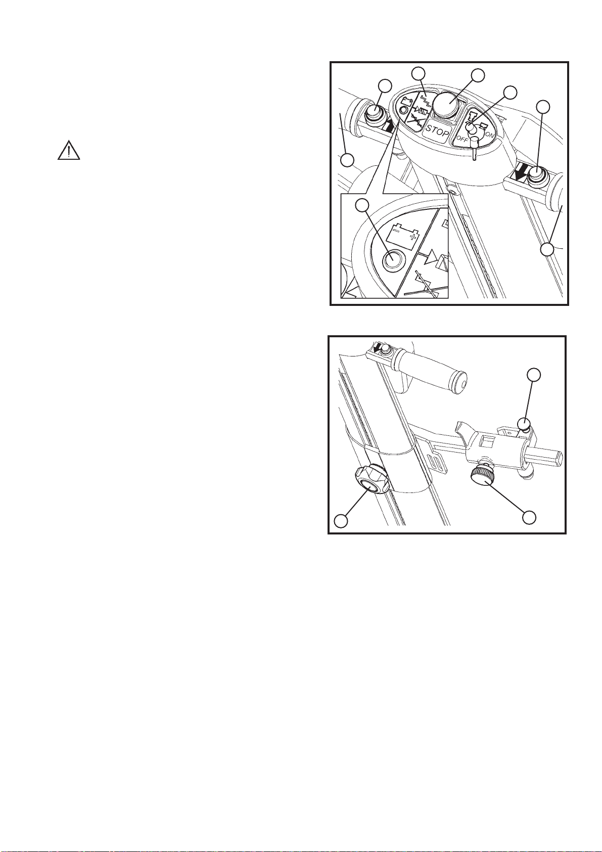
check the emergency stop (Fig. 4/b) efficiency•
Signals
check the battery charger signal efficiency (Fig. 4\d)•
check the•
gradient visual signal (Fig. 4\c) efficiency
.
ROBY body
battery charger•
voltage and net frequency complying with the provi-•
ded values of section 7.5.
7.4) Environmental conditions
temperature : from 32° F to +113° F / 0° C to + 45°•
humidity: max 90%•
7.5) Electrical connection
Battery charger input cable is 3 x 18 AWG (poles
number each section).
Connect the battery charger to a wall outlet.
Battery charger data
voltage rating (IN): 120V a.c.•
frequency (IN): 60 Hz•
voltage rating (OUT): 24 V d.c./3A•
8) DAILY USAGE
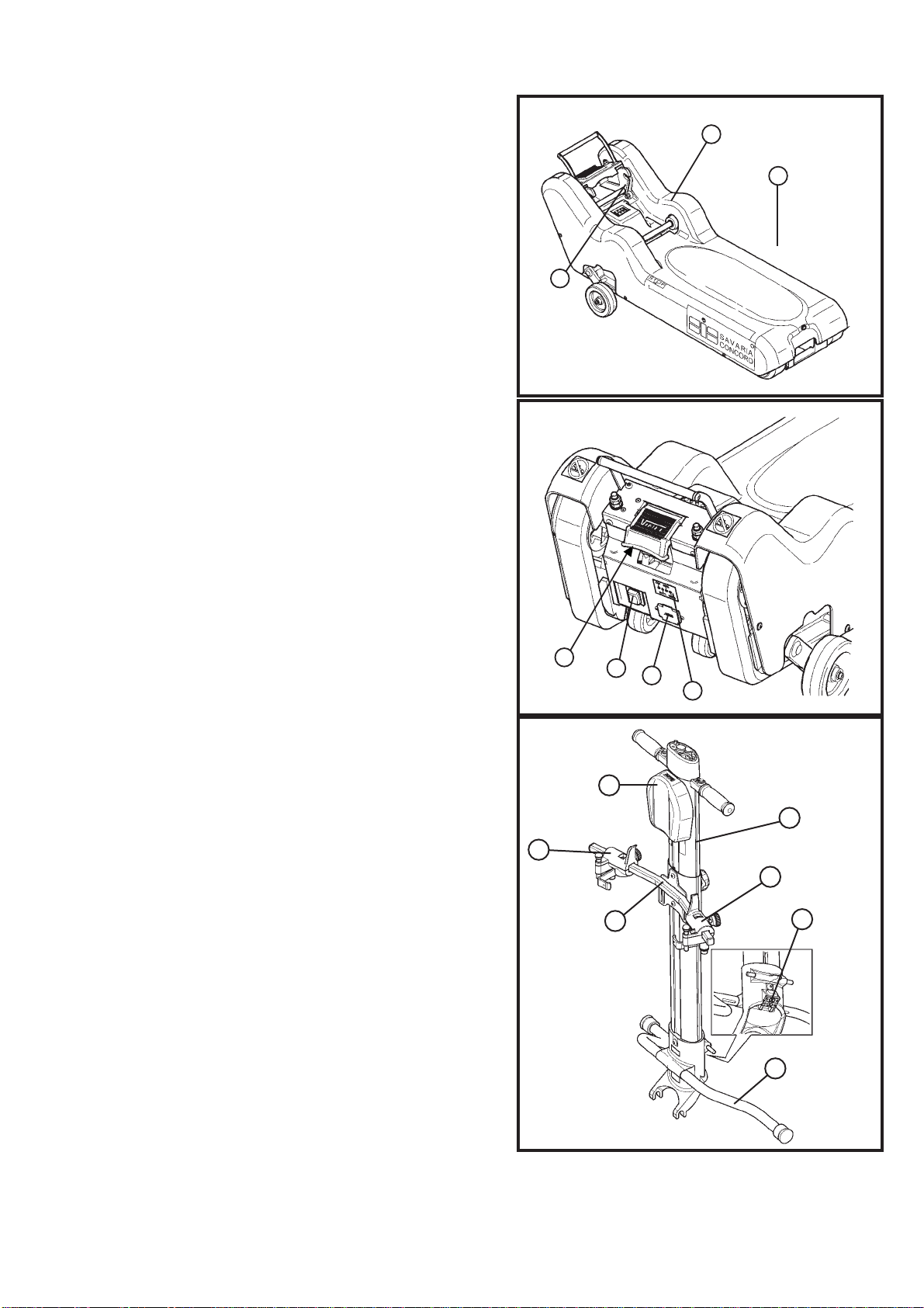
8.1) Steering and control bar post assembly
a) Insert the post (Fig. 11/a) at the u-hooks onto the
circular cross member (Fig. 11/b) on the base.
b) Incline the steering-bar post (Fig. 12/a) as shown by
the arrow (Fig. 11/b) until it locks into the base.
c) Once the steering-bar is locked (Fig. 12/a), push the
red plastic safety protective cover down onto the
post release lever (Fig. 12/b).
WARNING: Ensure that the ROBY cover is in
its proper position. In this configuration, the
electrical contacts outlet is engaged and the steering-
bar is locked in the work position. Switch the machine
on by inserting the key (Fig. 4/e); the push buttons
(Fig. 4/a) on the steering-bar allow the tracks to move
forward and backwards. If the safety protective cover
is not in its proper position, the ROBY does not run.
8.2) Steering-bar release
To release the steering-bar (Fig. 13/a) lift the red
plastic safety protective cover (Fig. 13/b); release the
red pedal (Fig. 14/b); push the steering-bar (Fig. 14/a)
forward as shown by the arrow (Fig. 14/c).
8.3) Attach a wheelchair
to the stairclimber
a) Lock the wheelchair brake. Insert the key
(Fig. 15/a) into the ROBY steering-bar control
panel key slot (Fig. 15) and release the emergency
stop button.
b) Press either the ascend or the descend button on
the steering-bar; move the stairclimber under the
wheelchair (Fig. 16/a).
c) To release the steering-bar post (Fig. 13/a) lift the
red plastic safety protective cover (Fig. 13/b);
release the red pedal (Fig. 14/b); push the
FIG. 11
FIG. 13
FIG. 12
FIG. 14

11
b
a
f
b
dc
a
d
a
b
a
b
c
e
c
e
b
steering-bar (Fig. 14/a) forward as shown by the
arrow (Fig. 14/c).
d) Push the post towards the wheelchair.
e) Unscrew (Fig. 17/b) the vertical height knob (Fig.
17/a); push the metallic central pushbutton (Fig.
17/c) and slide (Fig. 17/d) the wheelchair clamp
assembly up/down on the post until the crossbar is
vertically just under the vertical height of the
wheelchair handgrips (see Fig. 16).
NOTE: Carry out this operation holding the
crossbar as shown in Fig. 17/e.
f) Loosen each crossbar clamp (Fig. 18/a) knob (Fig.
18/b); slide horizontally until snug against
wheelchair vertical back support posts.
g) Lift each crossbar clamp piston (Fig. 19/a); swing
each metal hook to wheelchair arm and (Fig. 19/b)
release crossbar clamp piston (see Fig. 16/e) to
ensure each hook can’t open; tighten each crossbar
clamp knob (Fig. 18/b).
IMPORTANT: Do not clamp handles or other
objects that might slip off the wheelchair.
h) Move the post back to hooked position (Fig. 11/b);
hook post to base.
i) Use the base for leverage, if required (Fig. 16/f);
push the red plastic safety protective cover down
onto the post release lever (Fig. 12/b) by foot.
l) The machine activates (the green LED on the con-
trol panel lights); the wheelchair is properly hooked
and anchored to the stair climber.
m) Press downwards on the steering-bar; the
manual auxiliary wheels activate. Maneuver the
ROBY to the leading edge of either stair-flight to
perform an ascent or a descent (Fig. 27 and 29).
FIG. 18
FIG. 17
FIG. 16
FIG. 15

12
a
b
WARNING: Fasten the seat belt before
mounting a flight of stairs.
WARNING: Hold the steering-bar firmly,
whether on stairs or on a level floor.
8.4) Travel preparation
a) BATTERY
Check the battery charge once the ROBY is fully
assembled. First activate the machine without a
passenger before using the machine on stairs.
Using the machine when the indicator LED is
blinking can cause battery damage.
b) SIGNALS
Always check the operating panel on the handle-
bars for a tipping signal before entering onto
a staircase.
If the visual signal is not functioning, DO NOT
USE THE STAIRCLIMBER! Call Savaria Concord
techncial support.
c) EMERGENCY STOP
Check the emergency STOP operation (red
push-button on control panel).
press the push-button; the controls should be•
off-line
reset the push-button by pulling it upwards.•
If the emergengy STOP does not function, DO
NOT USE the stairclimber! Call Savaria Concord
technical support.
Do not move the stairclimber with a passenger
on board before completing all operations described
in section 8.3.
NEVER RELEASE YOUR GRIP ON THE
HANDLE-BARS WHILE CARRYING A PASSENGER!
8.5) Manual operation on a level floor
Perform movements and turns in manual mode:
a) Use the steering-bar as a lever; raise the frontside
of the ROBY to utilize the manual auxiliary wheels.
b) Move the ROBY towards you and turn in desired
direction. Proceed forward in desired direction.
8.6) Stair gradient check
Always perform the stair gradient check on
unfamiliar stairs:
a) Check that the step rise is not greater than 7.09
(in) 180 mm (Fig. 8).
b) In manual mode, without passenger, approach first
stage of stair to travel; press the push button control
(Fig. 4/a); advance on a section of stair; release the
push button; ensure the gradient indicator (Fig. 4\c) on
the steering-bar is green—gradient under 35°.
If the indicator is red—gradient above 35°—it is not
possible to travel on that staircase.
Green indicator: correct gradient
Red indicator: excessive gradient
8.7) Headrest adjustment
To adjust the headrest (Fig. 20/a): remove it and
adjust using the twoVelcro strips (Fig. 20/b).
WARNING: THE PERSON THAT USES THE
STAIRCLIMBER DETERMINES THE STABILITY OF
THE ROBY. TO AVOID UNSTABLE CONDITIONS,
PLEASE ADHERE TO THE FOLLOWING
GUIDELINES AT ALL TIMES.
8.8) Operation on staircase
Always place the ROBY so that the transported
passengers' shoulders are towards the ascent side.
If during stair operations the stairclimber does not
stop when you release the push button (up/down),
press the red emergency STOP push button on the
steering-bar control panel.
Follow the emergency stop instructions in
section 8.9.
8.8.1) Stair ascent operation
a) Guide the stairclimber to the stairs as in section 8.5.
With passenger on board, approach the first step of
the flight (Fig. 21/a).
if you travel just one flight, position the ROBY in the•
middle of the flight
if there is more than one flight of stairs, travel as near•
the handrail as possible or near the wall that delimits
the stair well; this position makes manual operation
on landings easier.
Ensure the stairclimber is perpendicular to the
steps; do not attempt to travel on staircases diagonally.
b) Press the ascend push button holding the steering-
bar firmly with two hands; travel up the flight until
the machine arrives at the nose of the last step-
riser (Fig. 22/b) with the STOP sticker on the base,
parallel to the last stair (Fig. 22/a).
FIG. 19

13
a
b
a
b
c
d
a
b
c) Release the push button control; slowly lower the
steering-bar (Fig. 22/c).
If the staircase includes two or more flights, operate
manually and approach the second flight. Repeat the
preceding operation.
WARNING:The small blocks on the tracks can
slide on the step edge during stairclimber
operation and when at a standstill; sliding can
cause the stairclimber to tip over forward. Use
caution when operating; hold the steering-bar
firmly; do not release grip.
8.8.2) Stair descent operation
a) Guide the stairclimber to the stairs as in section
8.5.With passenger on board, approach the first
step of the flight (Fig. 21/a); stop when the STOP
sticker on the base is parallel to the edge of the
stairs (Fig. 22/a) (Fig 22/b).
Stair with one flight
Move the ROBY to the center of the staircase, front
to back, with the front parallel with the step.
Stair with more than one flight
Move the ROBY to the center of the staircase, front
to back, with the front parallel with the step.To help
maneuver around the base of each flight, keep the
ROBY as close to the outer edge (wall side) as
is possible.
WARNING: Ensure the ROBY is always
perpendicular to the step.
b) Raise the steering-bar (Fig. 22/d) until the tracks
touch the lower step; press the descend push but-
ton and travel down the stairs taking care to hold
the steering-bar firmly with both hands.
c) At the end of each flight, the manual auxiliary
wheels (Fig. 23/a) automatically return to level floor
position for the next manual operation.
8.9) Staircase emergency stop
In case of an emergency stop on a staircase flight,
never release the steering-bar.
If you lock the ROBY, ensure it is stable before
releasing your hand grip from the steering-bar.
If the stairclimber stops during an ascent due
to a discharged battery, there may be enough power
to descend; reverse direction to attempt to bring the
passenger to a lower level.
8.10) Passenger release
a) At the end of each travel, lift the red plastic safety
protective cover (Fig. 13/b); release the red pedal
(Fig. 14/b); push the steering-bar forward (Fig. 14/a)
until the wheelchair touches the ground.
c) Raise the crossbar clamp pistons (Fig. 24/a) and swing
the red lever (Fig. 24/b) outwards; loosen the
crossbar clamp knobs (Fig. 25/a).
d) Lower the steering-bar and reattach it to
the chassis.
e) Move the ROBY manually.
8.11) Passenger recovery
IMPORTANT: In case of an emergency stop on
one flight, never release the steering-bar. If the
stairclimber stops during an ascent due to a discharged
FIG. 20
FIG. 21
FIG. 22

14
a
a
b
a
battery, there may be enough power to descend;
reverse direction to attempt to bring the passenger to
a lower level.
WARNING: If it’s not possible to descend to
a lower floor, move the machine by using the manual
descent lowering handle (Fig. 26/a) (supplied).
9) MAINTENANCE
Inspect the following parts during each service
check interval:
Competence level: O - Trained operator
Detail / Component Control frequency
a) Rubber tracks monthly
b) Steering-bar clamping monthly
c) Wheelchair clamping monthly
d) Battery before every use
e) Steering-bar connector monthly
f) Electrical protections monthly
g) Signals before every use
h) Emergency button before every use
Perform the following inspections and tests for each
of the preceding components—a to h.
a) Inspect the tracks to ensure they do not include
wear, marks, cuts, or excessively worn small blocks.
b) Ensure the wheelchair release mechanism is intact
and in working order.
c) The batteries are of a sealed type and are mainte-
nance free; keep them charged at all times; use the
supplied electrical cable and plug into a suitable
electrical socket.
d) Check the electrical wire; ensure it is not frayed
and in need of replacement.
e) Check that the battery charger pilot light indicator
is active.
f) Check that the emergency STOP is active. Push the
emergency stop button—the controls deactivate.
Reset the button by pulling it upwards.
If any one component fails an inspection test,
contact Savaria Concord technical support.
See section 2.
9.1) Periodic cleaning of the ROBY
Competence: O - Trained operator
Frequency: Quarterly
Turn off all power before disassembling any
electrical component.
FIG. 23
FIG. 24
FIG. 25
FIG. 26

15
ab
Clean the following external and internal areas to
ensure reliable ROBY operation:
remove the key and the power cable and shut off•
the power
unscrew the cover screws and remove the cover•
remove dust, dirt, and any accumulated grease•
once complete, reconnect the general connector•
and reassemble the cover.
Battery charger
For every 7 or 8 partial battery charges, at least
one charge should be a complete battery charge—
until the green LED displays GREEN (Fig. 27/b) (after
about 11 hours of charge); a complete charge helps
prolong battery life.
Do not use the ROBY while the
battery charges.
FIG. 27
9.2) ROBY does not start - Possible causes - solutions
Competence: O - Trained operator
Defects Possible causes Possible solutions
The ROBY does not move Starting key Insert the ON/OFF key
Pushed emergency STOP Pull the pushbutton upwards
Discharged battery Recharge the battery
Battery discharges
Replace the battery
immediately after a recharge
Discharged battery Safety block at a charge
percentage of 10%
If the malfunction persists, contact Savaria Concord technical support.
10)VIBRATIONS AND NOISE
a) Vibrations
The ROBY can induce passenger vibrations and
sound by the following means:
low frequency and moderate acceleration•
brief exposure cycles for the exposed persons.•
b) Noise: less than 70 db.
11) IN
FORMATION ABOUT ROBY PARTS
AND MATE
RIALS DISPOSAL
a) Rubber and plastic materials disposal
Put all materials for disposal in clean containers
and transfer them to authorized centres for
salvage and disposal according to the laws and rules
in force in your area.
b) Run-down battery disposal
Bring all used batteries to local depots that are
certified for safe battery disposal.
ORANGE: CHARGING
GREEN: CHARGED
FIG. 27b

16
b
d
a
12) ASCENT AND DESCENT OPERATIONS
12.1) Descent
Phase One: With the wheelchair properly hooked
up and the green light lit on the steering-bar control
panel, put pressure on the the steering-bar (Fig. 28/b)
such that the nose of the ROBY rises (Fig. 28/d)—the
manual auxiliary wheels activate (Fig. 28/c); move the
machine to the edge of the first stair of the
flight (Fig. 28/a).
Phase Two: Activate the descent pushbutton
until the STOP sticker—placed on the base of the
ROBY— is parallel (Fig. 29/a) to the edge of the first
stair (Fig. 29/b).
Phase three: Press the descend button (Fig. 29/c)—
FIG. 28
c
there is a one second delay—until the ROBY contacts
the first stair. Keep the descend button engaged—the
descent begins.
Phase four: When the ROBY reaches the end of
a flight, it levels out; put pressure on the steering-bar
(Fig. 28/b) such that the nose rises; push and turn the
ROBY; place it on the edge of the first stair of the
next flight (see Fig. 30); activate the descend pushbut-
ton until the STOP sticker—placed on the base of
the ROBY—is parallel (Fig. 29/a) to the edge of the
first stair (Fig. 29/b). Repeat Phase three.
WARNING: ALWAYS HOLD THE STEERING-
BAR FIRMLY!
12.2) Ascent
a
b
c
FIG. 29
FIG. 30
turn and push the
machine
LOW FLOOR HIGH FLOOR
Phase one: With the wheelchair properly hooked
up and the green light lit on the steering-bar control
panel, put pressure on the (Fig. 31/b) the steering-bar
such that the nose of the ROBY rises and the manual
auxiliary wheels activate; move the machine to the
edge of the first stair (Fig. 31/a).
Phase two: Activate the ascent pushbutton and
ascend until the ROBY reaches the last stair.
Phase three: At the last stair, stop the ROBY when
the STOP sticker on the base is parallel with the stair
(Fig. 32/a) (Fig. 32/b); put pressure on the steering-bar
(Fig. 32/c) such that the nose of the ROBY rises.
Phase four: At the top of the flight of stairs, and
once the machine is level, press downwards on the
steering-bar again to activate the manual auxiliary
wheels; pull and turn the machine to approach the first
stair of the next flight (see Fig. 33). Ensure the back
edge of the ROBY is parallel with the stairs. Engage the
ascend button and rise to the next flight or, if the final
destination is reached, release the wheelchair.
WARNING: ALWAYS HOLD THE STEERING-
BAR FIRMLY!

17
a
b
Turn and pull
the machine
FIG. 31
FIG. 32
c
a
b
LOW FLOOR HIGH FLOOR
FIG. 33

18
a
a
b
e
a
fc
a
c
b
d
90°
a
f
bc
e
d
g
d
13) Reversing the safety couplings
Most wheelchairs include thrust handles (Fig. 34/a),
however; some wheelchairs include a horizontal bar
on the rear part on the seat back (Fig. 35/a).
When a horizontal bar is in use, rotate the locking
group (Fig. 36/a) equipped with a second hole (Fig.
36/b) 90° so that the red hook (Fig. 36/c) grasps the
horizontal bar from downwards and not laterally; this
clamps the wheelchair to the steering-bar with the
same safety of traditional wheelchairs.
The following steps describe how to attach a
wheelchair equipped with a horizontal bar to
the ROBY:
1) Remove the clamping screw placed in the edge of
the steering-bar (Fig.36/d) and loosen the locking
handwheel (Fig. 36/e).
2) Extract the safety clamp (Fig. 36/a) toward the out-
side (Fig. 36/f).
3) Rotate the locking group (Fig. 37/a) 90° (Fig. 37/b) to
the left for the left side clamp and to the right for
the right side clamp.
4) Insert the rotated coupling through the hole (Fig.
37/c) into the arm (Fig. 37/d).Tighten the setscrew
placed in the edge of each steering-bar arm.
5) Adjust the steering-bar (Fig. 38/a) to the wheelchair
seat back (Fig. 38/b). Pull the safety piston (Fig. 38/c),
hook the horizontal bar (Fig. 38/d) using the hook
(Fig. 38/e) and release the piston (Fig. 38/c).
FIG. 34
FIG. 35
FIG. 36
FIG. 37
FIG. 38
NOTE: Ensure that the piston (Fig. 38/c) is placed
under the red hook (Fig. 38/e) such that it can’t be
released from the wheelchair (Fig. 38/d).
6) Lock the coupling by turning the
handwheel (Fig. 38/f).
7) Lift the arms (Fig. 38/g) until the point at which the
red hook (Fig. 38/e) is placed in contact
with the horizontal bar (Fig. 38/d) is reached.

19
FIG. 39
ROBY STAIRCLIMBER
GENERAL SIDE
VIEW FRONT VIEW OF
HANDLEBAR FRONT VIEW
OF DRIVE ROBY
TECHNICAL FEATURES
Rated Load Power supply voltage Range Weight Speed
130 [daN] CC 24 [V] 23 [FLOORS] 47 [daN] 16,4 fpm Data
04/04/06
Cod.
8620702
We reserve the right to alter the specification without prior notification.
If the measurements "min. 38,19 - min 32,28 - max. 35" don't fit the above table, ROBY can't be used on the stair.

20
FIG. 40
Other manuals for Roby
1
Table of contents
Other Savaria Fitness Equipment manuals