Sawo STP-30-1/2 User manual

www.sawo.com
MANUAL
STP_ML(En0109)
Congratulations on your purchase of a SAWO Steam Generator.
Please read the manual carefully before using the steam generator.
Models
STP-30-1/2
STP-35-1/2
STP-40-1/2
STP-45-1/2
STP-50-1/2
STP-45-3
STP-60-3
STP-60-C1/3
STP-75-3
STP-75-3-C1/3 STP-90-3
STP-90-C1/3
STP-120-3
STP-150-3
STEAM
GENERATOR
3.0 kW
3.5 kW
4.0 kW
4.5 kW
6.0 kW
7.5 kW
9.0 kW
12.0 kW
15.0 kW
4.5 kW
5.0 kW
Code Problem Solution
Drain failureE10
Communication failure.E11
Temperature is greater than
the maximum temperature.
E12
No master steam generator
connected
Dip switch setting is incorrect. Check dip
switch settings. If no problem can be found,
contact the retailer.
E13
Check the RJ12 cable. If the area where
cable is located has many other cables, it
can cause EMC problems.
If no problem can be found, contact
the retailer.
Check that the drain valve is connected and
not blocked. Clean the level probes. If no
problem can be found, contact the retailer.
Water level too high and
operation not permitted.
E6
Water level too low and
operation not permitted. Check that water supply is open and there is
enough pressure. Check solenoid valve.
Clean level probes. If no problem can be
found, contact the retailer.
E7
Illogical combination of
water level measurements. Clean level probes. If no problem can be
found, contact the retailer.
E8
Fill failure Check that water supply is open and there is
enough pressure. Check solenoid valve.
Clean level probes. If no problem can be
found, contact the retailer.
E9
Check that the drain valve is not blocked.
Clean the level probes. If no problem can be
found, contact the retailer.
Contact qualified electrician or maintenance
personnel before using the steam generator
again.

SAWO Steam Generator
2
S
A
WO Steam Generator
AA
TABLE OF CONTENTS
3
5
9
10
5
6
6
6
7
7
7
7
7
8
Before Installation
Instructions of Use
Maintenance
Steam Generator Parts
Assembly and Installation
TABLE OF CONTENTS
3
4
21
DIP Switches in the Steam Generator
22
Troubleshooting
Steam Room Guidelines
Steam Generator
11
Plumbing
11
Water Supply
11
Connecting Water Filter and Softener
11
Steam Outlet
12
Steam Guard Overflow
12
Steam Head
12
Drain
12
Attaching Autodrain
12
Power Wiring
13
Technical Data
13
Electrical Diagram
14
Installing the Temperature Sensor
16
Installing Control Unit
18
Connection of SAWO
20
Terminal Connection of
20
On/Off Mode
Standby Mode
Auto Drain Mode
Temperature / Timer
Key Lock
Changing the Values
Optional Features
Cabin Light / Dimmer
Fan
Demand Button
8
Switching Between Different Modes
8
Scent Pump
Decalcification
9
Level probe cleaning
10
Tank cleaning
10
Control to the PCB
Demand Button (optional)
Steam Generator Series Connection
21

The Steam Room must be fully enclosed, complete with walls, door, flooring and ceiling.
Rubber linings (e.g. gaskets) are recommended for the door to effectively seal the heat
and the steam inside the Steam Room.
If tiles are used for the flooring or some other smooth surface material, provide suitable
anti-skid strips or rubberized mats to prevent slipping resulting to injury.
Materials used for the walls and ceiling should have water-resistant, non-corrosive
surfaces such as tiles, marbles, molded acrylic, or other non-porous materials. The
ceiling should be dome-shaped to prevent the dripping of condensate.
A drain must be provided in the flooring.
Heating, venting or air conditioning devices should not be installed inside the Steam
Room.
Steam Room windows should be double paned.
Limit the Steam Room ceiling to a height of 2.5 meters. Exceeding 2.5m will require a
higher-rated steam generator.
Steam Room Guidelines
Before Installing
1.
2.
3.
4.
5.
6.
7.
8.
3 4
Use the following information together with the consultation of your contractor, architect
or designer in determining all factors necessary in providing a suitable and safe steam
room.
Check that the supply voltage is suitable to your steam generator.
Ensure that the steam generator kilowatt corresponds to the volume of your steam room.
Refer to Technical Data (Page 13).
Steam Generator Parts
ContactorTerminal for
incoming line
Terminal for
steam generator
accessories
Transformer
Autodrain
Drain outlet
PCB cover
Solenoid Valve
Water Level Probe Steam Outlet
Steam guard overflow
For illustrative purposes only.
Power switch
For illustrative purposes only.
Not for use for wiring. For
component identification only.
WARNING
The voltage of the light output is 230VAC. Sawo
recommends to use less than 50V for the steam
room lightning. Use appropriate transformer for
lower voltages. Sawo is not responsible of
damages caused by using higher voltage inside
the steam room.

Instructions of Use
5
There are four different operation modes in the unit: Off, On, Standby and Drain. The user
can easily switch between different modes, making the steam bathing more convenient
with less energy consumption.
To use steam room the control unit needs to be in the On mode. In the On mode, the
steamer is active, the temperature in the steam room will be kept in the preferred, set
temperature, with occasional discharge of steam.
However, if the steam room is not used constantly, the generator can be set to Standby
mode. The water in the tank is kept warm, with minimal energy usage. The generator is
able to produce steam shortly after the unit is switch back to On mode for the convenience
of the users.
More details about the different modes and how to move between them can be found in the
text and graph following.
On/Off Mode
On/Off Mode
On Mode
When the power switch is turned “On” the software versions of the control board and the
user interface will be displayed for 1 second each. Then the control unit will go to “Off” mode.
In the “Off” mode, the display is blank.
The auto drain can be disabled or enabled in the “Off” mode. Press and hold the Down
button, then press the Power button. The display will show “Adr oFF” or “Adr on” as
feedback.
For "On" mode press "Power" button.
First, the set steam room temperature is displayed blinking for 5 seconds. Then the user can
change the following settings; session time, temperature and fan (not all the models have
the same features), by pressing the corresponding button in the control unit. The up and
down arrow buttons can be used to increase and decrease the values.
If no buttons are pressed for 10 seconds, the set temperature for the steam room will be
displayed.
When the session time expires, the control unit will go to the “Standby” mode.
Power
Standby
Down Up
Temp./Timer
Fan/Scent pump
Cabin lights/Dimmer
6
Standby Mode
Auto drain Mode
Temperature / Timer
1. Short press “Standby” button
2. Short press “Power” button
3. When session time expires.
In standby-mode text “Standby” is displayed altering with the remaining standby time. To
change remaining time press “up” or “down” arrow buttons. If the time is changed during the
first 5 minutes after the activation of standby-mode, the time will be saved as a new default
standby time.
To activate on-mode again short press the “standby” button
To go off-mode:
1. Press “Power” button for more than 3 seconds.
2. Press “Standby” button for more than 3 seconds to activate autodrain process, after
which the unit goes automatically off-mode. (If autodrain feature is not available the
unit will go off-mode)
3. Wait until remaining standby time expires and autodrain process (if available)
completes
During the standby-mode the water in the steam generator tank is kept hot. This minimizes
the time to produce steam when generator goes to on-mode next time.
Standby-mode can be activated by any of the following methods when the unit is in on-mode:
User can cancel auto drain process whenever the water level in the tank is at normal or below
normal level by pressing “power” button for more than 3 seconds.
To start Auto Drain in "On" mode press "Power" or "Standby" button followed by a long press
(more than 3 seconds) of "Standby" button.
The temperature/timer button can be used to switch between the temperature and session
time.
When the steam generator is switched on, the set temperature at the steam room is
displayed. It can be changed by pressing up and down buttons.
If the temperature/timer button is pressed, the remaining session time will be displayed. It
can be changed by pressing up and down buttons. The session time will be saved as the
default session time if it was changed within the first 5 mins from the beginning of “On”
mode.
If the temperature/timer button is pressed again, the unit will return displaying the set
temperature. In addition, if no buttons are pressed for 10 seconds, the set temperature of
the steam room will be displayed.
The draining process will take about 10 minutes.
After the Standby time runs out, control unit automatically goes to Autodrain mode. When
the drain cycle is activated, the generator’s tank will be filled first. The water inside the tank
will be cooled down, so the valve can be opened, as the water is not boiling hot anymore.
The auto drain feature automatically drains the water system after every use. The tank is
flushed and will remain empty until the steam generator is used again.

78
Changing the values
The key lock function is set automatically if it was left active
during the previous operation.
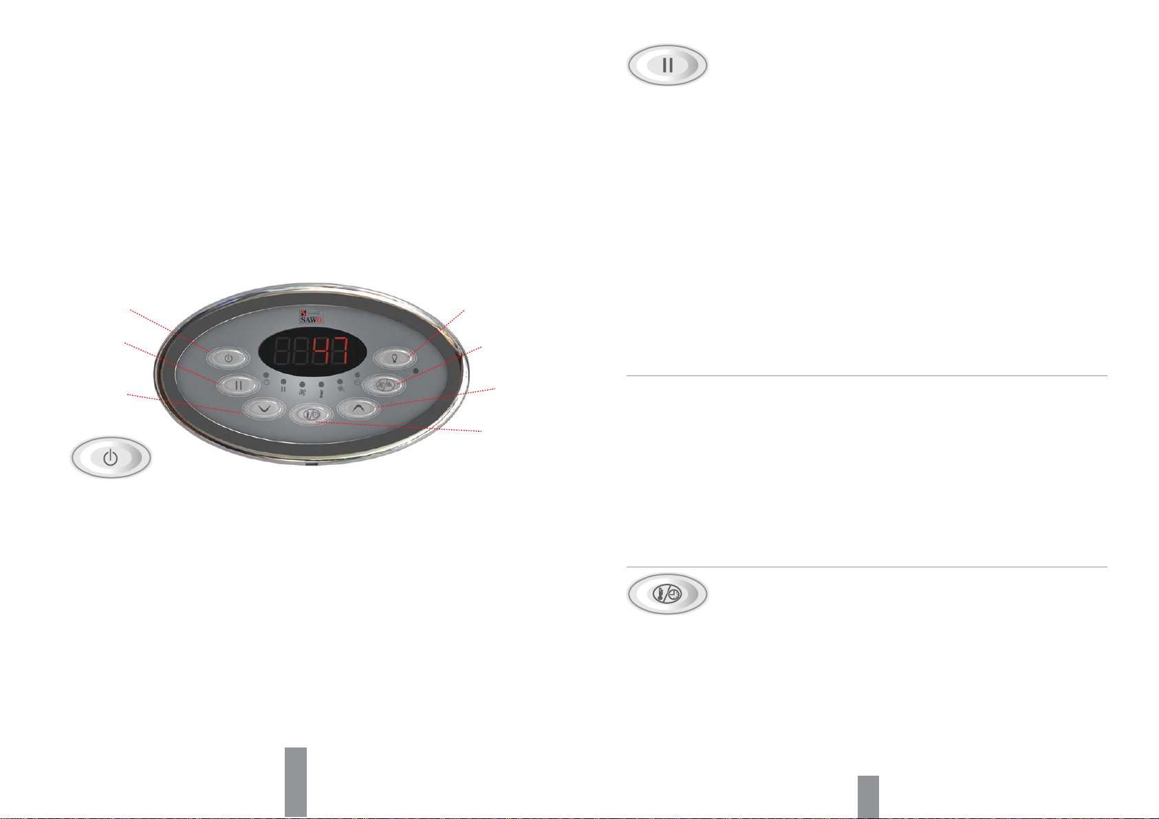
Key Lock
Optional Features
Cabin Light /
Dimmer
Demand Button
Switching Between
Different Modes
Fan
Scent Pump
Press On/Off button for more than 3 seconds.
Press On/Off button or demand button.
Press On/Off button for more than 3 seconds.
Press Standby button.
Press On/Off button or Standby button or when the
session time expires.
Press On/Off button or Standby button or demand
button.
Press On/Off button for more than 3 seconds or
when the drain time expires.
Press Standby button for more than 3 seconds or
when the session time expires.
1.
2.
3.
4.
5.
6.
7.
8.
OFF ON
S/B DRAIN
1
2
34
5
6
8
7
Lock and unlock the key pad by pressing the up and down buttons at the
same time for more than 5 seconds. A high beep will confirm the
activation and the deactivation.
Only On/Off, Standby and Cabin light buttons are usable when the
key pad is locked. If other buttons are pressed, “----” is shown in the
display.
The up and down buttons are repetitive. Holding the up or down button
will cause the value to in- or decrease with an increased rate.
Pressing the up or down button in the settings menu will in- or decrease
the currently displayed value. A value cannot be in- or decreased above
or below its maximum or minimum value, if it is tried low tone buzzer
alarms the user.
If no keys are pressed within 5 seconds, changes in the values are
confirmed.
Fan can be operated in "On" and "Standby" modes. Long press (more
than 3 seconds) "Fan/Scent" button in order to switch fan on/off.
In the “On” mode, if no keys are pressed for 10 seconds, the display will
automatically display the set temperature.
(Optional features are not available in every model)
If the dimmer is not present and the cabin light button is pressed, it will
switch the cabin light On/Off. When cabin light is ON red LED-indicator
next to Cabin light button in the panel is lit.
If dimmer feature is available press “cabin light” button to turn cabin lights
on and off. Light intensity value will be shown in the display and by press-
ing “up” or “down” arrows cabin light can be brighten or dimmed respec-
tively.
If cabin lights are already turned on long press “cabin light” button to
activate dimmer in order to change light intensity.
If no buttons are pressed within 5 seconds the last cabin light intensity
value will be saved.
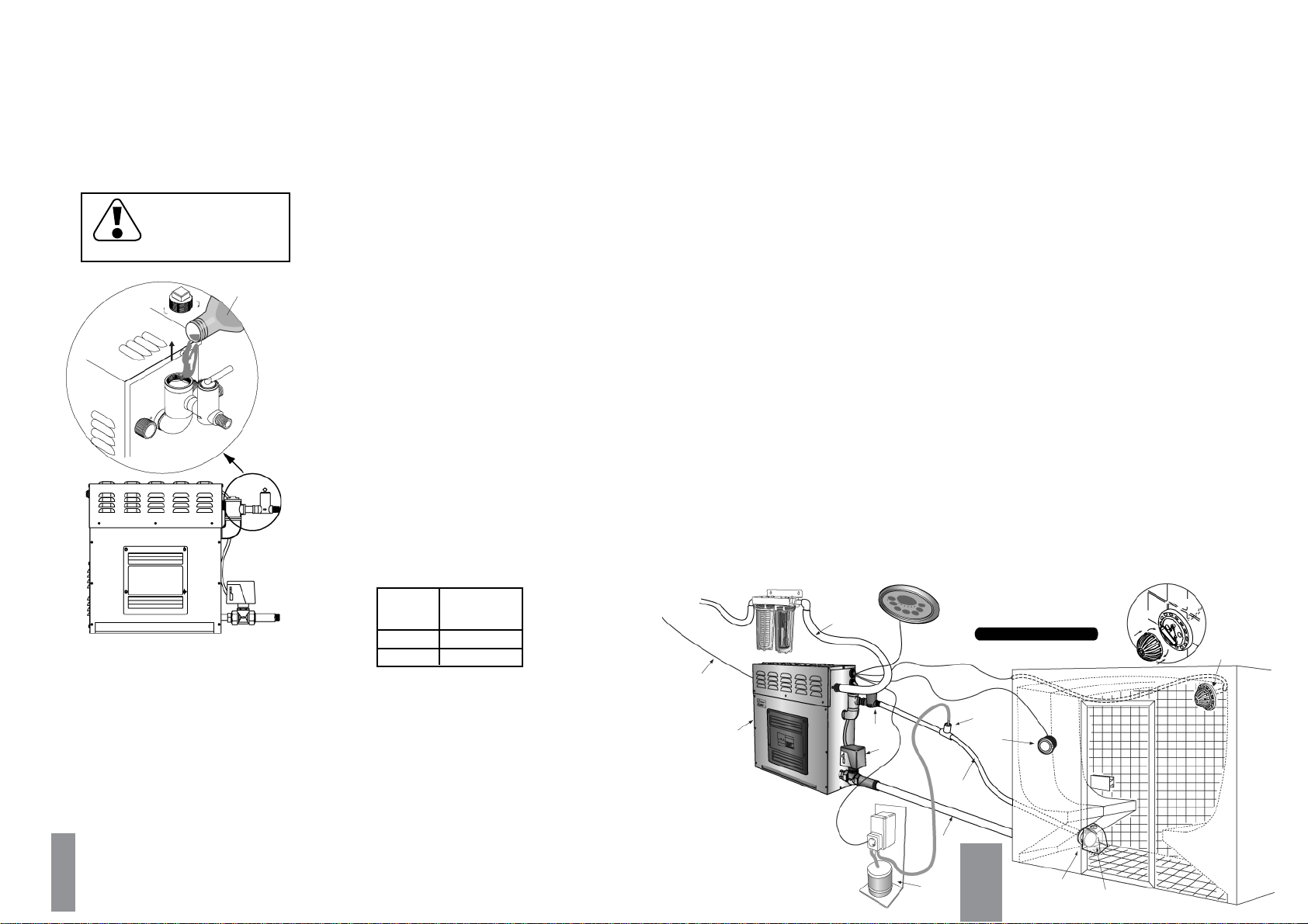
Before switching scent pump on make sure there is enough aroma in the
aroma container. Never run the scent pump dry.
Scent pump can be operated in "On" mode only. In order to switch scent
pump on/off short press “Fan/Scent” button. The Scent pump is allowed
to be turned on only when the water in the tank is boiling.
Each time the scent pump is switched on the interval of the scent pump
functioning is displayed. Interval can now be changed by pressing “up” or
“down” arrow buttons between 1 (scent pump is activated every 20 mins)
and 20 (pump on continuously). If no keys are pressed within 5 seconds,
the previously displayed value will be shown again and the scent pump
setting is saved.
If scent pump is on when the session time expires or the steam generator
is turned off by pressing “power” button, scent pump will turn off too.
Scent pump “on” and “interval” settings are saved and pump starts
automatically on the next session.
To switch off the scent pump short press “Fan/Scent” button in “On”
mode.
When the aroma oil is changed, check that the pipeline is not broken or it
does not leak. It is also recommended to wash the fragrance container
between changes, especially when using different fragrances.
The pump is easy to refill quickly: short press “Fan/Scent” button in “On”
mode to activate interval value display. Press and hold “Up” arrow button
to reach max. value 20 and scent pump will run continuously. It will take
about 10 seconds for every 1 meter of pipeline for aroma liquid to reach
the pump. As soon as the aroma liquid has reach the pump reset the
pump functioning interval as preferred.
Use only fragrances meant for steam generator use. Follow the instruc-
tions in the fragrance packing.
Pressing the "Demand" button when the steam generator is in "Off" or
Standby" mode will switch the control unit to "On" mode.
A separate demand button can be installed on any desired location
including inside the steam room. Press of the demand button will immedi-
ately release extra steam for 30 seconds.

10
Assembly and Installation
1.
2.
3.
4.
5.
6.
7.
8.
9.
Steam generator has to be installed outside the steam room.
The steam generator has to be installed in an upright position only.
Install water filter and softner or alike when necessary.
Leave enough space for service and maintenance of the generator.
For illustrative purposes only.
Temperature sensor
Demand
Button
Water source Water Filter / Softerner
Water inlet
Power supply
Drain
Steam Head Steam Head
Cover
Steam line
Autodrain
Dosing Nozzle
Steam Head
Steam
generator
Scent Pump
Cap
Control unit
Location of the steam generator has to be near the steam room. Place it within 7.5 meters
to the steam room.
Provide a level surface to install steam generator. Side hole slots are provided for wall
mounting. Make sure that the steam generator is secured and is level when mounted on the
wall.
The steam generator must not be installed outdoors or areas that may damage the unit due
to climate conditions.
Do not install the steam generator or plumbing lines in unheated attic or any locations where
water could freeze.
The steam generator must not be installed in areas near flammable or corrosive materials
or chemicals such as gasoline, paint thinners, chlorine or the like.
2. Level probe cleaning
a.
b.
c.
Disconnect steam generator from main supply before opening generator’s covers. Only
licenced electrician or professional maintence person can open covers and do cleaning.
Use adjustable wrench to deattach 3 wires from level probe. Make sure that when connect-
ing wires back, wires are connected to right probes
Use adjustable wrench to remove level probe. Clean tip of the pins from impurities using
sandpaper. Don’t damage plastic coating on pins. If coating is damaged, replace level
probe. Tighten level probe by hands and use adustable wrench only for final tightening.
3. Tank cleaning
a.
b.
c.
Disconnect steam generator from main supply before opening generator’s covers. Only
licenced electrician or professional maintence person can open covers and do cleaning.
Clean level probe as stated in 2.a to 2.b.
Remove temperature fuse and tank temperature sensor from terminal block.
d.
e. Remove heating elements and clean deposits from the elements.
Remove deposits from bottom and sides of the tank. Open bottom plug to wash away
deposits. Don’t use autodrain valve since big particles can block autodrain valve.
f. Attach bottom plug and use teflon pipe seal if needed
g. Attach heating elements. Make sure that temperature fuse and tank tempesensor are on
the top of heating element. Inserting heating element upside down will prevent the tempera-
ture fuse from working
For illustrative purposes only.
9
Decalcifying Solution
Maintenance
Tap water contains impurities, for example lime, that can cause calcium deposit and
block the internal parts of the steam generator. To prevent this and prolong the
lifetime of steam generator it is recommended to have a water filter and water softener.
They are connected to the water source of the steam generator’s water inlet.
< 3 ºdH = very soft water, decalcification every 500 operation hours
3-6 ºdH = soft water, decalcification every 100 operation hours
6-9 ºdH = hard water, decalcification every 50 operation hours
9-18 ºdH = very hard water, decalcification every 30 operation hours
Frequency for decalcification:
Unit dH where 1 dH is 10 mg calcium in 1 liter of water
Use Decalcifying Solution as follows:
3-7.5
9-15 250
500
Decalcifying
Solution
(ml)
Steam
Generator
(kW)
For steam generators in commercial use (over 5
hours continuously daily) additional service plan
is recommended twice a year. Please contact
your service center for details.
SAWO Decalcifying Solution can be used for decalcification. Follow these guidelines to
perform preventative maintenance of the steam generator.
1. Decalcification
Turn on the steam generator and wait until
water inside the tank starts to boil. Turn off
the generator.
Remove the cap of angled tube in the steam
outlet piping. Before opening, make sure
that the generator is off. Cool down the
angled tube with wet cloth if needed.
Pour the solution into the water tank. Do it
slowly enough to prevent solution to flow
inside the steam pipe.
Close the cap firmly and let the solution stay
in the tank for 30 mins. Do not switch the
generator on.
Drain the water tank by one of the following
ways:
Repeat the step 5 two more times.
Press "Standby" button shortly to
activate standby mode and then press
again "Standby" button for more than 3
seconds to start auto drain.
Manually open the drain valve by pulling
the lever down.
a.
b.
1.
2.
3.
4.
5.
6.
WARNING
Never add the Decalci-
fying Solution when the
generator is on, it can
cause serious burns!

11
For illustrative purposes only.
Water Filter /
Softener
Plumbing
Water Supply
Connecting Water Filter and Softener
i
Steam Generator Side view
showing element
access panel
Overpressure
Valve
Steam
Outlet Valve
Thread:
1/2” BSP
Thread:
3/4” BSP / 1” BSP
Automatic
Drain
Water Inlet
Water Inlet
Power
Switch
The plumbing has to be done by a qualified licensed plumber. Plumbing should be in
accordance with national or local codes. Use unions for piping connections. Use only
prescribed brass piping or copper tubing. Never use black or galvanized pipe for the
plumbing as it can easily crack or damage.
Provide a shut off valve on the water source for the steam generator. Turn off the inlet
water line before installing the unit. Recommended water pressure is 1 to 3 bar and
maximum water pressure without water filter/softener is 8 bar. Water softener is recom-
mend to use.
Attaching the Autodrain
Attach the Brass tee into the outlet.
Attach the autodrain to the brass tee.
Open the cover of the steam
generator.
Put the wire through the hole on the
side of the steam generator.
Cover back the steam generator.
1.
2.
3.
4.
5.
6.
Drain
Drain valve is provided for maintainance. Set drain connection for your steam
generator according to national or local plumbing requirements.
Steam Head
downward
position
Steam room wall
min. 3mm
Steam Head
Top View
3
5
Terminal Block
DRAIN
Place the steam head on a safe area
where bathers cannot get in contact
with it as it can get very hot. The
steam head must be facing down-
wards. A teflon tape or equivalent
needs to be used on the thread for
tightening it. Avoid using a wrench to
tighten the steam head as it might get
scratched.
Steam Outlet
The steam must move in a continuous flow to the steam room. Do not istall valves on
the steam line. Use insulated, rated120ºC or higher, brass pipe or copper tubing for
steam line to connect to the steam head as permitted by codes. Slope the steam line
height by 20mm per meter towards the steam head to avoid trapping of the condensate
and eliminate steam trap that blocks the flow of the steam.
Steam Guard Overflow
Connect the wires in the terminal
block to its label.
Brass Tee
4
Twist
12
Autodrain
DRAIN
Steam Supply
Use a Teflon or a sealant
for the pipe threads
(1/2” BSP)
The overflow safety guard activates when there is an overpressure in the the steam
line. It automatically opens and releases the pressured steam. When this happens,
please check your steam line for servicing.
12

13 14
LIGHT
LIGHT
CONVERTABLE
TEMP
SENSOR
AUTOMATIC
DRAIN
FUSE
NTC2
TEMP
SCENT
FAN
PUMP
TEMP
SWITCH
(24VAC)DRAIN
(230VAC) LIGHT
(12VDC)ILL
TEMP
SENSOR
AUTOMATIC
DRAIN
FUSE
NTC2
TEMP
SCENT
FAN
PUMP
TEMP
SWITCH
(24VAC)DRAIN
(230VAC) LIGHT
(12VDC)ILL
Electrical Diagrams
3.0 kW | 3.5 kW | 4.0 kW | 4.5 kW | 5.0 kW
220-240V
1N~
L
POWER INPUT
NG
380-415V
2N~
Power Wiring
C
S
CONTACTOR
WATER
FEED
SOLENOID
VALVE
CONTROL
BOARD
CONTROL
L
HEATING
ELEMENT
NG
GROUND
230VAC in
FAN
SCENT PUMP
24VAC IN CONT. DRAIN FILL PE
PROBE1
PROBE2
PROBE3
COMMUNICATION
SWITCH
FUSE NTC2
TRANSFORMER
610
6.0 kW | 7.5 kW
380-415V
3N~
220-240V
1N~
C
CONTACTOR
HEATING
ELEMENT
C
S
WATER
FEED
SOLENOID
VALVE
CONTROL
BOARD
CONTROL
POWER INPUT
GROUND
230VAC in
FAN
SCENT PUMP
24VAC IN CONT. DRAIN FILL PE
PROBE1
PROBE2
PROBE3
COMMUNICATION
SWITCH
LNG
CONTACTOR
FUSE NTC2
TRANSFORMER
L2 N GL1L3
CONVERTABLE WARNING
Do not connect the elements
to the power supply directly.
Only a qualified electrician should do the Electrical wiring connections.
Check the power supply before installing your unit. Single Phase connection, a 220-240V
supplied is required. Use two-wire supply source and equipment grounding wire of single
phase connection.
The installation must include switch for all pole disconnection. Circuit breaker with 3mm
control gap is recommended.
A 90ºC / 600V (HO7RN-F) rated insulated copper wire is required for SAWO steam generators.
Check size of wires in Ampere Chart in accordance with the National Electrical Code and local
electrical code.
Technical Data
PLS. NOTE: This table is for steam rooms built in with light walls (tempered glass or acrylic. Steam rooms
with thick walls or ventilation, please use higher kilowatt steam generators
Model kW Steam
Room
Volume
(m³)
VoltageHeating Element
(V)
(kW) Type
Number
Wire
Size
mm² Width Depth Height
Size of Steam Generator
(mm)
PhaseCurrent
(A)
2.5
2.5
4.0
2.5
4.0
2.5
4.0
2.5
4.0
2.5
6.0
2.5
8.0
2.5
4.0
6.0
2.5
550 160 435
1N /
2N
1N /
2N
1N /
2N
1N /
2N
1N /
2N
1N
3N
1N
3N
STP-30-1/2 3.0 3 max 2 x 1.5 kW STG-150
STG-200
STG-150
STG-250
STG-250
STG-250
STG-250
STG-150
STG-150
STG-200
STG-200
STG-200
STG-150
STG-200
STG-200
STG-250
Weight
12
12
12
12
12
14
14
14
17
17
17
550 160 435
220 - 240 /
380 - 415
220 - 240 /
380 - 415
220 - 240 /
380 - 415
220 - 240
380 - 415
380 - 415
380 - 415
380 - 415
380 - 415
220 - 240 /
380 - 415
14
8
16
9
17
10
20
12
22
8
26
9
33
11
18
22
7
STP-35-1/2 3.5 3.5 max
550 160 435STP-40-1/2 4.0 4 max
550 160 435STP-45-1/2 4.5 2 - 5
380 - 415STP-45-3 4.5 2 - 5 550 210 435
550 160 435STP-50-1/2 5.0 2 - 6
550 210 435
3N
STP-60-3 6.0 3 - 10
6.0
2.5
1N
3N 14
220 - 240 /
380 - 415
220 - 240 /
380 - 415
26
9550 210 435STP-60-C1/3 6.0 3 - 10
550 210 435STP-75-3 7.5 4 - 15
8.0
2.5
1N
3N 14
33
11 550 210 435STP-75-C1/3 7.5 4 - 15
STP-90-3 8.0
2.5
1N
3N
380 - 415 40
13 550 260 4359.0 8 - 20
17
STP-90-C1/3 8.0
2.5
1N
3N
220 - 240 /
380 - 415 40
13 550 260 4359.0 8 - 20
550 260 4353NSTP-120-3 12.0 15 - 28 550 260 4353NSTP-150-3 15.0 22 - 40
1 x 1.5 kW
1 x 2.0 kW
2 x 2.0 kW
1 x 2.0 kW
1 x 2.5 kW
3 x 1.5 kW
2 x 2.5 kW
3 x 2.0 kW
3 x 2.0 kW
3 x 2.5 kW
3 x 2.5 kW
6 x 1.5 kW
6 x 1.5 kW
6 x 2.0 kW
6 x 2.5 kW
(kg)

15
LIGHT
CONVERTABLE
TEMP
SENSOR
AUTOMATIC
DRAIN
FUSE
NTC2
TEMP
SCENT
FAN
PUMP
TEMP
SWITCH
(24VAC)DRAIN
(230VAC) LIGHT
(12VDC)ILL
TEMP
SENSOR
AUTOMATIC
DRAIN
FUSE
NTC2
TEMP
SCENT
FAN
PUMP
TEMP
SWITCH
(24VAC)DRAIN
(230VAC) LIGHT
(12VDC)ILL
Installing the Temperature Sensor
(for illustrative purpose only)
Figure 1
TEMP
Terminal Block
On a surface where there is no obstruction below it.
Height has to be 1.2-1.5 meters above the floor.
It should be away from the steam head so that thesteam
will not hit the sensor directly.
The sensor has an integrated 9-meter cable. If longer
cable is needed, please consult your SAWO technician.
An 8mm hole is required to insert the temperature
sensor. Do not create bigger or smaller hole. Clean
the hole before inserting the sensor.
Make a hole in the cable lead-in on the side of
the generator to pull the cable through. Connect
the cable in the terminal block marked as
"TEMP". See figure 2.
The temperature sensor has to be installed:
a.
1.
2.
3.
b.
c.
4.5 kW | 6.0 kW | 7.5 kW
9.0 kW
380-415V
3N~
380-415V
3N~
CONTROL
C
CONTACTOR
HEATING
ELEMENT
C
S
WATER
FEED
SOLENOID
VALVE
CONTROL
BOARD
CONTROL
POWER INPUT
GROUND
230VAC in
FAN
SCENT PUMP
24VAC IN CONT. DRAIN FILL PE
PROBE1
PROBE2
PROBE3
COMMUNICATION
LIGHT
SWITCH
LNG
CONTACTOR
FUSE NTC2
TRANSFORMER
L2 NG
L1L3
HEATING
ELEMENT
C
CONTACTOR
POWER INPUT
GROUND
L3 L2 L1 N G TRANSFORMER
S
WATER
FEED
SOLENOID
VALVE
CONTROL
BOARD
230VAC in
FAN
SCENT PUMP
LIGHT
24VAC IN CONT. DRAIN FILL PE
PROBE1
PROBE2
PROBE3
COMMUNICATION
SWITCH
FUSE NTC2
220-240V
1N~
9.0 kW | 12.0 kW | 15.0 kW
380-415V
3N~
C
CONTACTOR
HEATING
ELEMENT
S
WATER
FEED
SOLENOID
VALVE
CONTROL
BOARD
CONTROL
POWER INPUT
GROUND
230VAC in
FAN
SCENT PUMP
24VAC IN CONT. DRAIN FILL PE
PROBE1
PROBE2
PROBE3
COMMUNICATION
SWITCH
L3 L2 L1 N G
FUSE NTC2
TRANSFORMER
TEMP
SENSOR
AUTOMATIC
DRAIN
FUSE
NTC2
TEMP
SCENT
FAN
PUMP
TEMP
SWITCH
(24VAC)DRAIN
(230VAC) LIGHT
(12VDC)ILL
Before installation main supply of the generator must be switch off from the
circuit braker.
TEMP
16
The temperature sensor comes along with the SAWO steam generator. It is recom-
mended to use only Sawo temperature sensor with Sawo generator as it may other-
wise not function correctly.Temperature sensor wiring should not be routed near
power cables or hot areas as it may cause electronic interference or damage to the
wires.

17 18
4.
5.
Figure 4
6.
Screw or glue the sensor cover to the
wall. Cover the temperature holder by
twisting the cap. Figure 4.
Pull the temperature sensor through
the steam room wall. Do not apply
staples or other material that may
damage the cable.
Insert the temperature sensor into the
sensor holder. Loosen the metal plate
to insert the temperature sensor.
Fasten the metal plate to tighten the
temperature sensor into the holder.
Apply silicone sealant on the hole in
the wall to create a moisture seal (Fig.
3). Make sure that there is no trace of
silicone on the sensor as it may
interfere its reading.
7.
AB
160 mm
84 mm
Wall
C
OPTIONAL
Interface Holders
Contact your SAWO distributor
Rectangle
Oval
Figure 3
Fig. 5
Silicone Sealant
Cable
Wall
Installation Instructions
Installing Control Unit
If the control is attached to a
concrete wall, provide a
control holder or equivalent
to mount the control into it.
NOTE
Check the most suitable area to place your steam generator control. The control and the
steam generator should be accessible for the user and maintenance. Do not install the
control unit inside the steam room! The cable of the control is 7.5 meters.
Mount the control in the wall, according to the specifications given below. Follow illustra-
tion.
SAWO Steam Control sets the temperature of your steam room. Mount the steam control
unit on an accessible area outside the steam room. It is recommended not to place the
steam control near to showers or similar wet places.
Never attempt to modify or to fix the steam control. Ask your licensed technician or your
nearest service centre for repair.
Before installation mains supply of the generator must be switch off from the circui breaker.

19 20
Connection of SAWO Control to the PCB.
Innova
Steam Generator
Control
230V 1N~
3,0 kW
KATSOOHJEISTA
TÄRKEÄTLISÄOHJEET
LÄGG MÄRKE TILLDE
VIKTIGA
TILLÄGGSANVISNINGARNA
BEACHTEN SIE DIE
ZUS
ÄTZLICHEN WICHTIGEN
ANWEISUNGEN IN DER
BEDIENUNGSANLEITUNG
READ THE MANUALFOR
ADDITIONALIMPORTANT
INSTRUCTIONS
Fan
(optional)
Light Scent Pump
(optional)
Before installation make sure that the generator is disconnected from the mains by switching off
the circuit breaker
1.
2.
3.
4.
5.
6.
7.
Note that there are two black RJ jacks on the board. One is for the control cable and the
other one for the optional slave unit. The control cable and slave cable can be connected
to either of these jacks, the order is insignificant.
Unscrew PCB cover on the side of the generator to get access on the PCB.
Guide the RJ12 control cable through the cable lead-in hole on the side of the generator
and then behind the side panel as described in the drawing below to reach RJ jacks on the
corner of PCB
Fasten the PCB cover and the top cover of the generator
Turn the mains on and switch on the power switch in the back of the generator
The software version should be displayed in the control unit
Turn the control unit on“On”mode to check it works properly
P100W
230VAC P100W
230VAC
Max.
Power Max.
Power Max.
Power
Innova Steam
Generator Control
Terminal Block
SCENT
FAN
PUMP
TEMP
SWITCH
(24VAC)DRAIN
(230VAC) LIGHT
(12VDC)ILL
Demand Button (optional)
Terminal Connection of
Make sure that polarity is right “ILL” output is +12VDC
and 20mA.
Before installation make sure that the mains is disconnected
from the generator by turning off the circuit breaker.
1. Open the top cover of the generator
Guide the cable through cable lead-in on the side of
the generator.
Connect the wires to their designated places in the
terminal block.
If the demand button has light connect the light wire
on the "ILL" labeled terminal
3.
4.
2.
Terminal Block
SCENT
FAN
PUMP
TEMP
SWITCH
(24VAC)DRAIN
(230VAC) LIGHT
(12VDC)ILL
SCENT
FAN
PUMP
TEMP
SWITCH
(24VAC)DRAIN
(230VAC) LIGHT
(12VDC)ILL
Terminal Block
SCENT
FAN
PUMP
TEMP
SWITCH
(24VAC)DRAIN
(230VAC) LIGHT
(12VDC)ILL
If you have optional
dimmer in steam genera-
tor, make sure that the
ligths are dimmable before
connecting. Steam genera-
tor uses phase control to
regulate power for lighting.

Steam Generator Series Connection
21
DIP Switches in the Steam Generator
Standby time
Standby
Duration
Mode Switch
6Switch
7Switch
8
4h 0 0
6h 0 0
12h 0 1
18h 0 1
0
1
0
1
Unlimited 1 0 0
4h 1 0 1
4h 1 1 0
4h 1 1 1
Slave
No. Switch
1Switch
2
100
201
310
411
Dipswitches for other Functions Dipswitches for
Naming Slaves
1 = ON
= OFF
0
Possible errors are:
Troubleshooting
Check the wire between the fuse and the
control unit. Fuse has probably overheated.
The reason for it needs to be discovered
before using the steam generator again.Anew
fuse is needed.
If no problem can be found, contact the retailer.
Temperature fuse defect.E5
Temperature sensor 1
not connected. Check the wire between the sensor and the
control unit.
If there is no problem with the wires and they
are correctly installed, check the sensor.
If no problem can be found, contact the
retailer.
E1
Temperature sensor 1
short circuit.
E2
Temperature sensor 2
not connected.
E3
Code Problem Solution
Temperature sensor 2
short circuit.
E4
Session Time
Session
Time Switch
2Switch
3Switch
4
10min 0 0
15min 0 0
20min 0 0
30min 0 0
0
0
1
1
45min 0 1 0
1h 0 1 0
2h 0 1 1
4h 0 1 1
Switch
5
0
1
0
1
0
1
0
1
6h 1 0 0 0
8h 1 0 0 1
12h 1 0 1 0
18h 1 0 1 1
Unlimited 1 1 0 0
10min 1 1 0 1
10min 1 1 1 0
10min 1 1 1 1
22
Dipswitch
No.: Function On Off
8CabinLight
7
6
5
4
3
2
1
30-55°C
Dimmer option
enabled Dimmer option
disabled
Present
Present
Connected
Yes 30-50°C
Not Present
Not Present
Not Connected
No
Fan
Scent Pump
Auto Drain
Temperature range
Slave Unit
Slave Number
Slave Number
Standby time can be set according to
user preferences by setting dip
switches on the power controller board
Session time can be set according to user
preferences by session dip switches on the
power controller board.
If an error occurs, the steam generator will be switched off. There will be a warning beep
to alarm the user every 2 seconds. The code for the error will be displayed blinking in the
control panel, see the table below.
Please note, only a qualified electrician or maintenance personnel are allowed to make
the service operations and repairs!
If an error occurs in one of the slave units, error message is followed by slave number. For
example: E1 -> S2 -> E1 ->S2... Pressing ON/OFF button disables the slave and rest ot
the generators can operate normally.
DIMMER
FAN
SCENT PUMP
DRAIN
TEMP
SLAVE
STANDBY
SESSION
Steam Generator
Control
Master
Steam Generator
DIP SW
3 = OFF DIP SW
3 = ON
2 = OFF
1 = OFF
DIP SW
3 = ON
2 = ON
1 = OFF
Slave 1
Steam Generator
Slave 2
Steam Generator
Slave 3 Slave 4
RJ12 Cable
Other manuals for STP-30-1/2
1
This manual suits for next models
13
Table of contents
Other Sawo Iron manuals

Sawo
Sawo STS45-1 User manual

Sawo
Sawo MINI COMBI Series User manual

Sawo
Sawo STN-30-1/2 User manual

Sawo
Sawo STP-30-1 User manual

Sawo
Sawo Super Savonia Combi User manual

Sawo
Sawo STN Series User manual

Sawo
Sawo NORDEX COMBI NRC-80NS User manual

Sawo
Sawo STR45-1 Assembly instructions

Sawo
Sawo STP-30-1/2 User manual