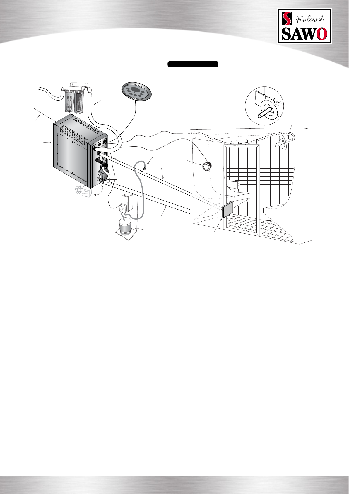
Sawo STN Series User manual

DISTRIBUTOR’S MANUAL
2 Heating Elements 3 Heating Elements
6 Heating Elements
3,0 kW
3,5 kW
4,0 kW
4,5 kW
5,0 kW
4,5 kW
6,0 kW
7,5 kW
9,0 kW
12,0 kW
15,0 kW
STN
Steam Generators

Table of
Contents
Water Level Probe
Electrical Diagrams
Software Versions
Software Compatibility
Room temperature sensor
Cabin Light
Demand Button
Scent Pump
Maintenance
Spare parts
Decalcication
Tank Cleaning
Troubleshooting
23
24
25
16
16
19
19
20
21
21
22
23
26
Introduction
STP Package
Installation
STP Control Panel Instructions of Use
Technical Data
PCB Parts
DIP Switches
Steam Generator Dimensions
Choosing Correct Kilowatt Size Steam
Generator
Piping
Steam Head Location
OFF / ON Mode
Standby Mode
Auto drain Mode
Switching Between Different Mode
Temperature / Timer
Key Lock
Changing the Values
Cabin Light / Dimmer
Fan
Scent Pump
Demand Button
Standby Time
Session Time
First Block Of 8 Switches
Dipswitches For Other Functions
Steam Generator Series Connection
Dipswitches For Naming Slaves
4
5
7
7
8
9
9
9
10
10
10
11
11
11
11
14
14
14
14
15
15
3
4
6
8
12
13
14

TECHNICAL GUIDE
STN Steam Generators www.sawo.com | info@sawo.com 3
Introduction
Before installing or servicing a steamgenerator, one must understand these basic issues which are signicant on the performance
of the steamgenerator unit.
• WATER PRESSURE
The water pressure required for the STP steamgenerators is 2-8bar or 30-120psi. Below or above the pressure requirement
may lead to the damage or malfunction of the water inlet.
• ELECTRICAL SUPPLY
Advise or check breaker if it is in perfect condition and correct size compared to steam generator’s power rating. Check the
supply voltage is suitable for steam generator.
• STEAM GENERATOR LOCATION
The steam generator location must be strategic for servicing and maintenance. Do not place the steam generator inside the
steamroom or outdoors. Make sure that water or liquids cannot come in touch with the generator. Generator is not splash water
proof. Floor drain is needed to prevent water damages in case there is a leakage from the pipe.
• STEAM GENERATOR CONTROL LOCATION
Steamgenerator control unit must be installed outside the steamroom. Moisture inside the steamroom may damage the
control. A demand button can be installed inside the steamroom for switching purposes.
• SENSOR WIRE
Steam room temperature sensor is supplied with a 9m wire. If longer wires are needed, use 2 x 0.5mm2 to 2 x 1.0mm2 cable
for extension.
• WATER FILTERS
It is recommended to install a water lter when having a steamgenerator. The water lter lessens the water sediments which
causes clogged up that can destroy the steamgenerator.

4www.sawo.com | info@sawo.com TECHNICAL GUIDE
STN Steam Generators
185mm
220mm
485mm
560mm
310mm
485mm
560mm
STN Package
Inclusions:
Water Inlet
3/4” BSP
2 Heating Elements
3 Heating Elements
6 Heating Elements
Water Inlet
3/4” BSP
Power
Switch
Power
Switch
Steam Outlet
Valve
Steam Outlet
Valve
Automatic
Drain
Automatic
Drain
Thread: 1”
BSP
Thread: 1”
BSP
2 Heating Elements
3 Heating Elements
6 Heating Elements
Steam Head
(9kW, 12kW and 15kW include
two steam heads)
Steam Head Holder
Optional Items:
Steam Generator Dimensions For illustrative purposes only.
STN Controls
(Classic 2,0 | Stainless Steel Touch | Classic)
Temperature sensor with
wire and sensor holder
Aroma, Fan and Dimmer Functions
(Optional features)
Autodrain 7,5m RJ12 Cable
Demand Button Steam DoorAroma Pump
code:
size:
ST-746
790 x 1890mm
Decalcifying Solutions

TECHNICAL GUIDE
STN Steam Generators www.sawo.com | info@sawo.com 5
Choosing Correct Kilowatt Size Steam Generator
Ventilation increases adjusted room size by 30%
Medium walls increases adjusted room size by 25%
Heavy walls increases adjusted room size by 50%
Each 0.3m exceeding 2.4m in height increases adjusted room size by 15%
Maximum
room
Volume m³
2
2,5
3,5
4,5
6
7
10
14
18
23
27
34
44
54
65
kW
3
3,5
4
4,5
5
6
7,5
9
12
15
18 2x9kW
24 2x12kW
30 2x15kW
36 3x12kW
45 3x15kW
Materials
Light Walls
Acrylic / Synthetic materials.
Medium Walls
Glass, ceramic, porcelain tile.
Heavy Walls
Natural stones, marble stone,
concrete wall. Porcelain tiles
on top of concrete wall.
*Based on light walls
Example #1
Steam room has tiled walls. Tiles are not on top of thick concrete.
Example #3
Steam room acrylic walls.
Example #2
Steam room has tiled brick walls and high ceiling.
Room size:
Adjustment:
Steam Generator size:
Room size:
Adjustment:
Steam Generator size:
Room size:
Adjustment:
Steam Generator size:
2.1(h) x 1.4(w) x 1.5m(d) = 4.41m³
4.41m³ x 25% = 1.10m³
4.41m³ + 1.10m³ = 6m³
5kW
2.3(h) x 2.1(w) x 2.5m(d) = 12.08m³
0
12.08m³ + 0 = 13m³
9kW
2.7(h) x 2.1(w) x 2.5m(d) = 14.18m³
14.18m³ x 50% = 7.09m³
14.18m³ x 15% = 2.13m³
14.18m³ + 7.09m³ + 2.13m³ = 24m³
18kW
Medium walls add room size by 25%
Total, rounded up
Total, rounded up
Heavy walls add room size by 50%
Heigh ceiling add room size by 15%
Total, rounded up

6www.sawo.com | info@sawo.com TECHNICAL GUIDE
STN Steam Generators
Installation
Water Filter / Softener
Water source
Power supply
Water inlet
Control unit
Steam Line
Autodrain
Drain
Dosing nozzle
Temperature Sensor
Scent Pump
Steam Head
Over
Pressure Demand
Button
Steam
generator
1. Location of the steam generator has to be near the steam room. Place it within 7,5 meters to the steam room.
2. Steam generator has to be installed outside the steam room.
3. The steam generator must not be installed outdoors or areas that may damage the unit due to climate conditions.
4. Do not install the steam generator or plumbing lines in unheated attic or any locations where water could freeze.
5. The steam generator must not be installed in areas near ammable or corrosive materials or chemicals such as gasoline,
paint thinners, chlorine or the like.
6. Provide a level surface to install steam generator. Side hole slots are provided for wall mounting. Make sure that the steam
generator is secured and is level when mounted on the wall.
7. The steam generator has to be installed in an upright position only.
8. Install water lter and softener or alike when necessary.
9. Leave enough space for service and maintenance of the generator.
For illustrative purposes only.

TECHNICAL GUIDE
STN Steam Generators www.sawo.com | info@sawo.com 7
Piping
Running the steam line down and then up will create a
“steam trap” blocking the ow of the steam.
No trapping
Union
Do not use 1 steam
line when installing 2
steam generators.
(kW)
3-7,5
9 and above
Steam
Line
1/2”-3/4”
3/4”
Steam Line Sizes
Steam Head Location
Recommended Steam Head Location

8www.sawo.com | info@sawo.com TECHNICAL GUIDE
STN Steam Generators
STN Control Panel Instructions of Use
There are four different operation modes in the unit: Off, On, Standby and Drain. The user can easily switch between different
modes, making the steam bathing more convenient with less energy consumption.
To use steam room the control unit needs to be in the On mode. In the On mode, the steamer is active, the temperature in
the steam room will be kept in the preferred, set temperature, with occasional discharge of steam.
However, if the steam room is not used constantly, the generator can be set to Standby mode. The water in the tank is kept
warm, with minimal energy usage. The generator is able to produce steam shortly after the unit is switch back to On mode
for the convenience of the users.
More details about the different modes and how to move between them can be found in the text and graph following.
On/Off Mode
When the power switch is turned “On” the software versions of the control board and the user interface will be displayed for 1
second each. Then the control unit will go to “Off” mode. In the “Off” mode, the display is blank.
The auto drain can be disabled or enabled in the “Off” mode. Press and hold the Up button, then press the Power button. The
display will show “Adr oFF” or “Adr on” as feedback.
On Mode
For “On” mode press “Power” button.
First, the set steam room temperature is displayed blinking for 5 seconds. Then the user can change the following settings;
session time, temperature and fan (not all the models have the same features), by pressing the corresponding button in the
control unit. The up and down arrow buttons can be used to increase and decrease the values.
If no buttons are pressed for 10 seconds, the set temperature for the steam room will be displayed.
When the session time expires, the control unit will go to the “Standby” mode.
Power
Down
Cabin lights/Dimmer
Fan/Scent pump
Up
Temp/Timer
Standby

TECHNICAL GUIDE
STN Steam Generators www.sawo.com | info@sawo.com 9
OFF ON
S/B DRAIN
1
2
3 4
5
6
8
7
Standby Mode
During the standby-mode the water in the steam generator tank is kept hot. This minimizes the time to produce steam when
generator goes to on-mode next time.
Standby-mode can be activated by any of the following methods when the unit is in on-mode:
1. Short press “Standby” button
2. Short press “Power” button
3. When session time expires.
In standby-mode text “Standby” is displayed altering with the remaining standby time. To change remaining time press “up”
or “down” arrow buttons. If the time is changed during the rst 5 minutes after the activation of standby-mode, the time will
be saved as a new default standby time.
To activate on-mode again short press the “standby” button.
To go off-mode:
1. Press “Power” button for more than 3 seconds.
2. Press “Standby” button for more than 3 seconds to activate autodrain process, after which the unit goes automatically off-
mode. (If autodrain feature is not available the unit will go off-mode)
3. Wait until remaining standby time expires and autodrain process (if available) completes.
Auto drain Mode
The auto drain feature automatically drains the water system after every use. The tank is ushed and will remain empty until
the steam generator is used again.
After the Standby time runs out, control unit automatically goes to Autodrain mode. When the drain cycle is activated, the
generator’s tank will be lled rst. The water inside the tank will be cooled down, so the valve can be opened, as the water is
not boiling hot anymore.
The draining process will take about 10 minutes.
User can cancel auto drain process whenever the water level in the tank is at normal or below normal level by pressing “power”
button for more than 3 seconds.
To start Auto Drain in “On” mode press “Power” or “Standby” button followed by a long press (more than 3 seconds) of “Stand-
by” button.
The maximum draining process will take about 10 minutes.
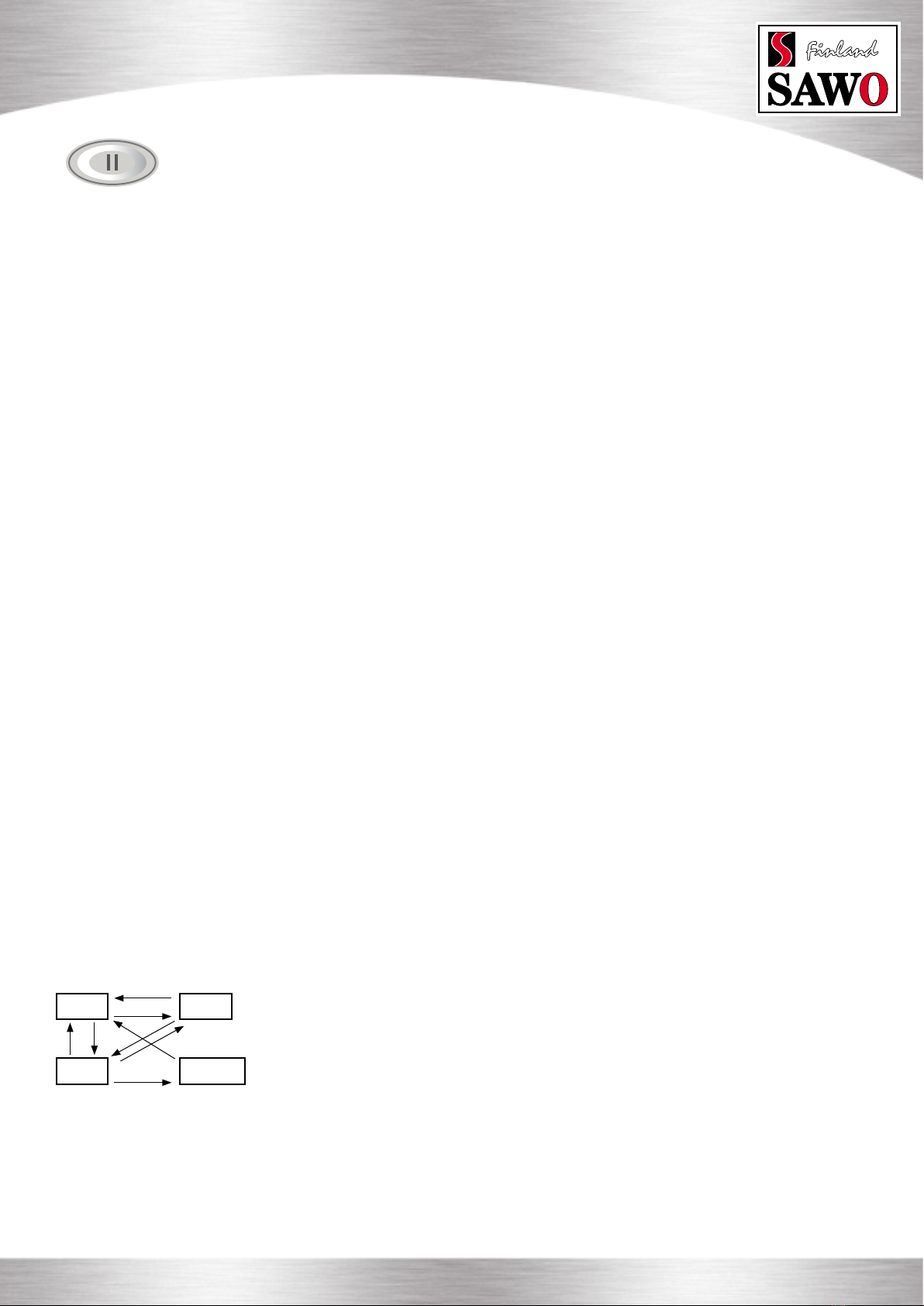
Switching Between
Different Modes
1. Press On/Off button for more than 3 seconds.
2. Press On/Off button or demand button.
3. Press On/Off button for more than 3 seconds.
4. Press Standby button.
5. Press On/Off button or Standby button or when the session time expires.
6. Press On/Off button or Standby button or demand button.
7. Press On/Off button for more than 3 seconds or when the drain time
expires.
8. Press Standby button for more than 3 seconds or when the session time
expires.

10 www.sawo.com | info@sawo.com TECHNICAL GUIDE
STN Steam Generators
Temperature / Timer
The temperature/timer button can be used to switch between the temperature and session time.
When the steam generator is switched on, the set temperature at the steam room is displayed. It can be changed by pressing
up and down buttons.
If the temperature/timer button is pressed, the remaining session time will be displayed. It can be changed by pressing up
and down buttons. The session time will be saved as the default session time if it was changed within the rst 5 mins from the
beginning of “On” mode.
If the temperature/timer button is pressed again, the unit will return displaying the set temperature. In addition, if no buttons
are pressed for 10 seconds, the set temperature of the steam room will be displayed.
Key Lock
Lock and unlock the key pad by pressing the up and down buttons at the same time
for more than 5 seconds. A high beep will conrm the activation and the deactivation.
Only On/Off, Standby and Cabin light buttons are usable when the key pad is locked. If
other buttons are pressed, “----” is shown in the display.
The key lock function is set automatically if it was left active during the previous operation.
Changing the values
Pressing the up or down button in the settings menu will in- or decrease the currently
displayed value. A value cannot be in- or decreased above or below its maximum or
minimum value, if it is tried low tone buzzer alarms the user.
The up and down buttons are repetitive. Holding the up or down button will cause the
value to in- or decrease with an increased rate.
If no keys are pressed within 5 seconds, changes in the values are conrmed.
In the “On” mode, if no keys are pressed for 10 seconds, the display will automatically
display the set temperature.

TECHNICAL GUIDE
STN Steam Generators www.sawo.com | info@sawo.com 11
Optional Features
(Optional features are not available in every model)
Cabin Light/Dimmer
If the dimmer is not present and the cabin light button is pressed, it will switch the cabin
light On/Off. When cabin light is ON red LED-indicator next to Cabin light button in the panel
is lit.
If dimmer feature is available press “cabin light” button to turn cabin lights on and off. Light
intensity value will be shown in the display and by pressing “up” or “down” arrows cabin
light can be brighten or dimmed respectively.
If cabin lights are already turned on long press “cabin light” button to activate dimmer in
order to change light intensity.
If no buttons are pressed within 5 seconds the last cabin light intensity value will be saved.
Fan
Fan can be operated in “On” and “Standby” modes. Long press (more than 3 seconds) “Fan/
Scent” button in order to switch fan on/off.
Scent Pump
Before switching scent pump on make sure there is enough aroma in the aroma container.
Never run the scent pump dry.
Scent pump can be operated in “On” mode only. In order to switch scent pump on/off short
press “Fan/Scent” button. The Scent pump is allowed to be turned on only when the water
in the tank is boiling.
Each time the scent pump is switched on the interval of the scent pump functioning is
displayed. Interval can now be changed by pressing “up” or “down” arrow buttons between
1 (scent pump is activated every 20 mins) and 20 (pump on continuously). If no keys are
pressed within 5 seconds, the previously displayed value will be shown again and the scent
pump setting is saved.
If scent pump is on when the session time expires or the steam generator is turned off
by pressing “power” button, scent pump will turn off too. Scent pump “on” and “interval”
settings are saved and pump starts automatically on the next session.
To switch off the scent pump short press “Fan/Scent” button in “On” mode.
When the aroma oil is changed, check that the pipeline is not broken or it does not leak. It
is also recommended to wash the fragrance container between changes, especially when
using different fragrances.
The pump is easy to rell quickly: short press “Fan/Scent” button in “On” mode to activate
interval value display. Press and hold “Up” arrow button to reach max. value 20 and scent
pump will run continuously. It will take about 10 seconds for every 1 meter of pipeline for
aroma liquid to reach the pump. As soon as the aroma liquid has reach the pump reset the
pump functioning interval as preferred.
Use only fragrances meant for steam generator use. Follow the instructions in the fragrance
packing.
Demand Button
A separate demand button can be installed on any desired location including inside the steam
room. Press of the demand button will immediately release extra steam for 30 seconds.
Pressing the “Demand” button when the steam generator is in “Off” or Standby” mode will
switch the control unit to “On” mode.

12 www.sawo.com | info@sawo.com TECHNICAL GUIDE
STN Steam Generators
Technical Data
Model kW
Steam
Room
Volume
(m³)
VoltageHeating Element
(V)(kW)
Type
Number
Wire
Size
mm²
Width Depth Height
Size of Steam Generator
(mm)
PhaseCurrent
(A)
Weight
(kg)
2,5
2,5
4,0
2,5
4,0
2,5
4,0
2,5
2,5
2,5
2,5
560 185 4851N /
2N
1N /
2N
1N /
2N
1N /
2N
3N
3N
STN-30-1/2 3,0 3 max 2 x 1,5 kW STG-150
STG-200
STG-150
STG-250
STG-250
STG-200
STG-200
STG-250
19
19
19
19
21
21
21
220 - 240 /
380 - 415
220 - 240 /
380 - 415
220 - 240
380 - 415
380 - 415
380 - 415
220 - 240 /
380 - 415
14
8
18
10
20
12
22
8
9
11
7
560 185 485STN-40-1/2 4,0 4 max
560 185 485STN-45-1/2 4,5 2 - 5
380 - 415STN-45-3
STN-45-C1/3
4,5 2 - 5 560 220 485
560 185 485STN-50-1/2 5,0 2 - 6
560 220 485
3N
STN-60-3 6,0 3 - 10
560 220 485STN-75-3 7,5 4 - 15
2,5
2,5
1N /
2N
STG-150
STG-200
19560 185 485220 - 240 /
380 - 415
19
9
STN-35-1/2 3,5 3,5 max 1 x 1,5 kW
1 x 2,0 kW
2 x 2,0 kW
1 x 2,0 kW
1 x 2,5 kW
3 x 1,5 kW
STG-1504,5 2 - 5 3 x 1,5 kW
2 x 2,5 kW
3 x 2,0 kW
STG-200 6,0
2,5
2,5
4,0
2,5
2,5
1N
3
3N
21220 - 240 /
220 - 240 /
380 - 415
26
16
9
20
12
7
560 220 485
1N
3
3N
21220 - 240 /
220 - 240 /
380 - 415
560 220 485
STN-60-C1/3 6,0 3 - 10 3 x 2,0 kW
3 x 2,5 kW
STG-250 220 - 240 /
220 - 240 /
380 - 415
8,0
4,0
2,5
1N
3
3N
2113
20
11
560 220 485STN-75-C1/3 7,5 4 - 15 3 x 2,5 kW
STG-150 26STN-90-3 2,53N380 - 415 13 560 310 4859,0 8 - 20 6 x 1,5 kW
STG-150 26STN-90-C1/3 8,0
4,0
2,5
1N
3
3N
220 - 240 /
220 - 240 /
380 - 415
40
23
13
560 310 4859,0 8 - 20 6 x 1,5 kW
4,0STG-200 26380 - 415 18 560 310 4853NSTN-120-3 12,0 15 - 28 6 x 2,0 kW
6,0STG-250 26380 - 415 22 560 310 4853NSTN-150-3 15,0 22 - 40 6 x 2,5 kW
NOTE!
Weight includes packing:
Carton box, sensor, control unit,
steamhead and autodrain valve.

TECHNICAL GUIDE
STN Steam Generators www.sawo.com | info@sawo.com 13
PCB Parts
Inputs
Room Temperature
Sensor
Demand Button
Communication
Inputs
Demand button
illumination
Scent pump
Light
Fan
Remarks
2 connectors
Remarks
4700hm R
limits current
Optional,
Triac output
Dimmer optional,
phase control
Optional, Triac output
Rating
NTC
No Switch
RJ12, 6P6C
Rating
12VDC, 20mA
230 VAC,
Max 100W
230 VAC,
Max 100W
230 VAC,
Max 100W
FUSE
F1 = 1.6A
F2 = 1.6A
230VAC
1N
SERIAL
NUMBER
24 VAC
IN CONTACTOR DRAIN FILL
TERMINAL
CONNECTORS
Demand button illumination:
GND
+12VDC, 25mA
Demand button switch contacts
Room temperature sensor, STP-RTS
Tank temperature sensor, STP-TTS
Temp Fuse
LIGHT
CONNECTION
DIMMER
COMPONENTS
DIP
SWITCHES
RJ
CONNECTOR
RANDOM NUMBER SOFTWARE VERSION NUMBER
WATER LEVEL PROBE
PE
AROMA PUMP
CONNECTION
FAN
CONNECTION
NOTE!
Polarity for demand button
illumination is important.
Polarities of other connections
are not important.

14 www.sawo.com | info@sawo.com TECHNICAL GUIDE
STN Steam Generators
DIP Switches
Standby
Duration
Mode
Switch
6Switch
7Switch
8
4h 0 0
6h 0 0
12h 0 1
18h 0 1
0
1
0
1
Unlimited 1 0 0
4h 1 0 1
4h 1 1 0
4h 1 1 1
Session
Time Switch
2Switch
3Switch
4
10min 0 0
15min 0 0
20min 0 0
30min 0 0
0
0
1
1
45min 0 1 0
1h 0 1 0
2h 0 1 1
4h 0 1 1
Switch
5
0
1
0
1
0
1
0
1
6h 1 0 0 0
8h 1 0 0 1
12h 1 0 1 0
18h 1 0 1 1
Unlimited 1 1 0 0
10min 1 1 0 1
10min 1 1 1 0
10min 1 1 1 1
Dipswitch
No.:
Function On Off
8 Cabin Light
7
6
5
4
3
2
1
30-55°C
Dimmer option
enabled Dimmer option
disabled
Present
Present
Connected
Yes
30-50°C
Not Present
Not Present
Not Connected
No
Fan
Scent Pump
Auto Drain
Temperature range
Slave Unit
Slave Number
Slave Number
DIMMER
FAN
SCENT PUMP
DRAIN
TEMP
SLAVE
STANDBY
SESSION
1=
=
ON
OFF 0
STAND-BY ON/OFF
DIP No. Function
8 Standby mode duration
7
6
5
4
3
2
1
Standby mode duration
Maximum session time
Disable standby mode
/ Enable standby mode
ON DIP ON DIP
FIRST BLOCK SECOND BLOCK
Standby time
Standby time can be set according to
user preferences by setting dip switches
on the power controller board
Session Time
Session time can be set according to
user preferences by session dip switch-
es on the power controller board.
First Block of 8 Switches
Dipswitches for other Functions

TECHNICAL GUIDE
STN Steam Generators www.sawo.com | info@sawo.com 15
DIMMER
FAN
SCENT PUMP
DRAIN
TEMP
SLAVE
OFF
STANDBY
SESSION
1=
=
ON
OFF 0
STAND-BY IN USE
DIMMER
FAN
SCENT PUMP
DRAIN
TEMP
SLAVE
OFF
STANDBY
SESSION
1=
=
ON
OFF 0
SKIP STAND-BY
ON DIP DIPONON DIP DIPON
Example #1 Example #2
Stand-by
Maximum
Session Time
Maximum
Stand-by Time
Slave
Scent
Fan
Dimmer
Temp
Drain
Stand-by in Use
30 min.
4 hrs.
Steam generator is MASTER.
Scent
Fan
Dimmer
Max. temperature is 50Deg.Cel
Enabled: Tank will be drained
right after stand-by mode has
expired.
0
0011
000
0
1
1
1
0
1
Stand-by
Maximum
Session Time
Maximum
Stand-by Time
Slave
Scent
Fan
Dimmer
Temp
Drain
Skip Stand-by
Unlimited
No effect since Stand-by is
Disabled.
Steam generator is MASTER
Disabled
Disabled
Disabled
Max. temperature is 50Deg.Cel
Enabled: Automatically drains.
Turn-off after 30mins.
1
1100
000
0
0
0
0
0
1
Steam Generator
Control Master
Steam Generator
DIP SW
3 = OFF
DIP SW
3 = ON
2 = OFF
1 = OFF
DIP SW
3 = ON
2 = OFF
1 = ON
DIP SW
3 = ON
2 = ON
1 = ON
DIP SW
3 = ON
2 = ON
1 = OFF
Slave 1
Steam Generator Slave 2
Steam Generator
Master
Steam Generator Slave 1
Steam Generator
Slave 3
Steam Generator Slave 4
Steam Generator
RJ12 Cable
LAST UNIT IN CHAIN
HAS JUMPER PLACED
JUMPER REMOVED JUMPER REMOVED
TO SLAVE 1
FROM CONTROL
JUMPER REMOVED WITH JUMPER
TO SLAVE 2
FROM MASTER
Ending Data Line
Make sure that the highlighted
jumper is always in the last PCB
of the chain. If there is only one
board, leave the jumper on that
board. If more than one board is
used, take the jumpers out of all
the boards, except the last one in
the chain.
Slave
No.
Switch
1
Switch
2
1 0 0
2 0 1
3 1 0
4 1 1
Dipswitches for
Naming Slaves
Steam Generator Series Connection

16 www.sawo.com | info@sawo.com TECHNICAL GUIDE
STN Steam Generators
Probe 3
Probe 2
Probe 1
PE
HEATING
ELEMENTS
POWER INPUT
S
WATER
FEED
SOLENOID
VALVE
CONTROL BOARD
230VAC in
FAN
SCENT PUMP
24VAC IN CONT. DRAIN FILL
PROBE1
PROBE2
PROBE3
LIGHT
FUSE NTC2
FUSE
NTC2
TEMP
SWITCH
+/- ill
Fan
Max
100W
Light
Scent Pump Auto
Drain
See page 21
12V
DC Switch
Temperature
Sensor
7,5 meters
STP
-Classic
STP
-Classic 2.0
STP
-SST
C
CONTACTOR
GROUND
SWITCH
TRANSFORMER
PE
3 core cable
4 core cable
220-240V
1N~
380-415V
2N~
GNL
N GL1L2
HEATING
ELEMENTS
CONTACTOR UNIT
It’s possible to connect totally 5 STP steam generators in a series. In this connection, steam generators
act as one big steam generator. Control unit and room temperature sensor are connected to MASTER steam generator.
Each slave must be given a number by DIP switches. This helps troubleshooting in case of malfunction. If an error occurs, in
one of the slave units, error message is followed by a slave number.
For example E1 -> S2 -> E1 -> S2.
Pressing ON/OFF button disables the slave and rest of the generators can operate normally. Slave generators must be checked
and reactivation happens by shutting down the whole steam generator chain. Either turning of main breaker for 5 seconds or
switching OFF all steam generatos from their main switch. Once chain is powered, disabled slave will be enabled.
Water Level Probe
Troubleshooting
Below are possible errors of a level probe.
E5 -
E6 -
E7 -
E8 -
E9 -
Temp fuse blows
Tank too full
Fill failure
Illogical water levels
Fill failure
Water level during
automatic drain
Water level during
normal operation
Low level water switch
Contactor OFF.
Electrical Diagrams
NOTE!
Water level measurement is done
between Probe and Tank.
CONVERTIBLE 3,0 kW | 3,5 kW | 4,0 kW | 4,5 kW | 5,0 kW
WARNING!
Do not connect the elements
to the power supply directly.

TECHNICAL GUIDE
STN Steam Generators www.sawo.com | info@sawo.com 17
CONVERTIBLE 4,5 kW |6,0 kW | 7,5 kW
4,5 kW | 6,0 kW | 7,5 kW
S
WATER
FEED
SOLENOID
VALVE
230VAC in
FAN
SCENT PUMP
24VAC IN CONT. DRAIN FILL
PROBE1
PROBE2
PROBE3
LIGHT
FUSE NTC2
220-240V
3~
220-240V
1N~
380-415V
3N~
C
CONTACTOR
C
GROUND
PE
SWITCH
PL
CONTACTOR
TRANSFORMER
5 core cable
HEATING
ELEMENT
H1
H2
H3
4 core cable
3 core cable
N GL
L3
L2L1
N GL3L2
L1
HEATING
ELEMENTS
CONTACTOR UNIT
CONTROL BOARD
FUSE
NTC2
TEMP
SWITCH
+/- ill
Fan
Max
100W
Light
Scent Pump Auto
Drain
See page 21
12V
DC Switch
Temperature
Sensor
7,5 meters
STP
-Classic
STP
-Classic 2.0
STP
-SST
380-415V 3N~
S
WATER
FEED
SOLENOID
VALVE
GROUND
230VAC in
FAN
SCENT PUMP
24VAC IN CONT. DRAIN FILL PE
PROBE1
PROBE2
PROBE3
LIGHT
SWITCH
FUSE NTC2
TRANSFORMER
5 core cable
HEATING
ELEMENT
C
CONTACTOR
N GL1L2
L3
HEATING
ELEMENTS
CONTACTOR UNIT
CONTROL BOARD
FUSE
NTC2
TEMP
SWITCH
+/- ill
Fan
Max
100W
Light
Scent Pump Auto
Drain
See page 21
12V
DC Switch
Temperature
Sensor
7,5 meters
STP
-Classic
STP
-Classic 2.0
STP
-SST

18 www.sawo.com | info@sawo.com TECHNICAL GUIDE
STN Steam Generators
CONVERTIBLE 9,0 kW
9,0 kW | 12,0 kW | 15,0 kW
S
WATER
FEED
SOLENOID
VALVE
230VAC in
FAN
SCENT PUMP
24VAC IN CONT. DRAIN FILL
PROBE1
PROBE2
PROBE3
LIGHT
FUSE NTC2
220-240V
3~
220-240V
1N~
380-415V
3N~
C
CONTACTOR
C
GROUND
PE
SWITCH
PL
N G
CONTACTOR
TRANSFORMER
L
HEATING
ELEMENTS
CONTACTOR UNIT
H1
H2
H3
H4
H5
H6
5 core cable
4 core cable
3 core cable
L3L2L1
N GL3L2
L1
CONTROL BOARD
FUSE
NTC2
TEMP
SWITCH
+/- ill
Fan
Max
100W
Light
Scent Pump Auto
Drain
See page 21
12V
DC Switch
Temperature
Sensor
7,5 meters
STP
-Classic
STP
-Classic 2.0
STP
-SST
380-415V 3N~
C
CONTACTOR
S
WATER
FEED
SOLENOID
VALVE
GROUND
230VAC in
FAN
SCENT PUMP
24VAC IN CONT. DRAIN FILL PE
PROBE1
PROBE2
PROBE3
LIGHT
SWITCH
FUSE NTC2
TRANSFORMER
5 core cable
H1
H2
H3
H4
H5
H6
N GL1L2
L3
HEATING
ELEMENTS
CONTACTOR UNIT
CONTROL BOARD
FUSE
NTC2
TEMP
SWITCH
+/- ill
Fan
Max
100W
Light
Scent Pump Auto
Drain
See page 21
12V
DC Switch
Temperature
Sensor
7,5 meters
STP
-Classic
STP
-Classic 2.0
STP
-SST

TECHNICAL GUIDE
STN Steam Generators www.sawo.com | info@sawo.com 19
Software Versions
STEAM
GENERATOR
PCB SOFTWARE
VERSION
NUMBER
INTERFACE
SOFTWARE
VERSION
NUMBER
*No Dots on display
*No Dots on display
STEAM
GENERATOR
PCB SOFTWARE
VERSION
NUMBER
INTERFACE
VERSION
SOFTWARE
NUMBER
The STP Generator software versions can be found on the stikcer placed on
the Steam Generator PCB and Interface PCB. It is also being displayed at the
Start-up.
Sticker locations for software versions
Software versions displayed at
Start-up
Software Compatibility
TOUCH USER INTERFACE BOARD
STP-BOARD
1,3 1,31,3 No
1,3 Yes
Yes
Yes
Yes
Yes
Yes
1,3
1,3
1,3
1,3
1,3
1,4 1,4
1,4
1,4
1,4
1,4
1,4
1,4
1,4
1,5
1,5
1,5
1,5
1,5
1,5
1,5
1,6
1,6
1,6
1,6
1,6
1,6
1,6
1,7
1,7
1,7
1,7
1,7
1,7
1,8
1,8
1,8
1,8
1,8
1,8
1,5 1,5
1,6 1,6
1,7 1,7
1,8 1,8
1,9 1,9
STP-BOARDTOUCH UIB TOUCH UIBCOMPATIBILITY COMPATIBILITY
Yes
Yes
Yes
Yes
Yes
Yes
Yes
No
No
No
No
No
No
No
CLASSIC USER INTERFACE BOARD

20 www.sawo.com | info@sawo.com TECHNICAL GUIDE
STN Steam Generators
Room Temperature Sensor
Before installation main supply of the generator must be switch off from the circuit braker.
The temperature sensor comes along with the SAWO steam generator. It is recommended to use only Sawo temperature
sensor with Sawo generator as it may otherwise not function correctly.Temperature sensor wiring should not be routed near
power cables or hot areas as it may cause electronic interference or damage to the wires.
The sensor has an integrated 9-meter cable. If longer cable is needed use 2 x 0,5 mm2 to 2 x 1,0 mm2 cable for extension.
1. The temperature sensor has to be installed:
Height 1,2-1,5 meters above the oor away from the steam
head so that the steam will not hit the sensor directly.
2. A 25mm hole is required to insert the temperature sensor.
Do not create bigger or smaller hole. Clean the hole before
inserting the sensor.
3. Make a hole in the cable lead-in on the side of the generator to
pull the cable through. Connect the cable in the terminal block
marked as “TEMP”. See gure 2.
4. Insert the temperature sensor through the steam room wall. Do
not apply staples or other material that may damage the cable.
5. Apply silicone sealant on the hole in the wall to create a
moisture seal (Fig. 4). Make sure that there is no trace of
silicone on the sensor as it may interfere its reading.
Fig. 1
Temperature
Sensor
Terminal Block
Ø 25mm
Push sensor
head to lock
Silicone Sealant
Wall
Cable
Push to the
wall to stick
Fig. 2
SAWO Steam Generator
(shown with cover removed)
Fig. 3
Fig. 4 Fig. 5
For illustrative purposes only.
This manual suits for next models
15
Table of contents
Other Sawo Iron manuals

Sawo
Sawo STP-30-1 User manual

Sawo
Sawo MINI COMBI Series User manual

Sawo
Sawo STP-30-1/2 User manual

Sawo
Sawo STS45-1 User manual

Sawo
Sawo NORDEX COMBI NRC-80NS User manual

Sawo
Sawo STR45-1 Assembly instructions

Sawo
Sawo STN-30-1/2 User manual

Sawo
Sawo Super Savonia Combi User manual

Sawo
Sawo STP-30-1/2 User manual