Check that...
You have correctly identified the wires
The connections are tight
No loose strands have been left out of
the connection block.
Reseal the approved outdoor rated
external terminal block
Warning
This is a Class 1 product and must be earthed.
Please read these instructions carefully before commencing any work.
This unit must be fitted by a competent and qualified electrician.
Install in accordance with the IEE Wiring regulations and current Building Regulations.
Check the pack and make sure you have all the parts listed.
To prevent electrocution switch off at the mains supply before installing or maintaining this fitting. Ensure other persons cannot
restore the electrical supply without your knowledge.
If you are in any doubt, please consult a qualified electrician.
If replacing an existing fitting, make a careful note of the connections.
This light should be connected to a circuit with a 30mA RCD fitted.
This product is not suitable for location in or near a marine environment.
The entire unit gets hot whilst on for a period of time, ensure the fitting is mounted out of arms reach.
Never put anything on the product or hang anything on any part of this product.
Waste electrical products should not be disposed of with household waste. Please recycle where facilities exist. Check with
your local authority or retailer for recycling advice.
Thank you for purchasing this light fitting. Please read the instructions carefully before use to ensure safe and satisfactory
operation of this product. Please retain these instructions for future reference.
Layout
Plan the desired layout of these fittings carefully, ensuring the cables will reach the distances between the junction box and the
each light fitting.
Avoid locating any cables in positions that would cause a hazard. Position cables and outdoor rated junction boxes
(not supplied) away from areas where they may be at risk from being cut, trapped or damaged.
We recommend that you use H05RN-F specification cable (not supplied) which is an outdoor grade, rubber sheathed cable.
The mains supply cable must have a minimum cross section area of 1.0mm2.
Cables must be protected using suitable conduit or plastic trunking.
Take care not to drill into any pipes or mains cables beneath the surface during mounting holes preparation.
Installation
Existing fittings must be completely removed before installation of a new product. Before removing the existing fitting, carefully
note the position of each set of wires.
Note that the switch is turned off before installation.
Ensure that the screws and cable entry points are sealed to maintain the IP rating of the product.
After deciding the layout of the light fittings ensure that the cables are long enough to connect to desired positions.
Follow the installation steps below to install.
• Determine the position of your light fitting taking into account the entry position of the cable and the ARROW indicating
which WAY UP the base is to be fitted. Make sure there is sufficient cable coming out of the wall to connect to the terminal
block. Ensure that the mounting surface is solid, preferably a brick or block wall and ensure that there are no other cables
or pipes beneath the surface.
• Separate the plastic back plate from the fitting by removing the two screws on the both side of the fitting. use the back plate as
a template and mark the 2 fixings holes, making sure the back plate is correctly aligned and horizontal. Use appropriate fixings
to secure the back plate to the wall.
• Use a sharp object such as a screwdriver to pierce the rubber grommet in the back plate. Thread the cable through the hole
and fix the mounting box to the wall using the screws and plugs supplied. take care not to damage any concealed wiring.
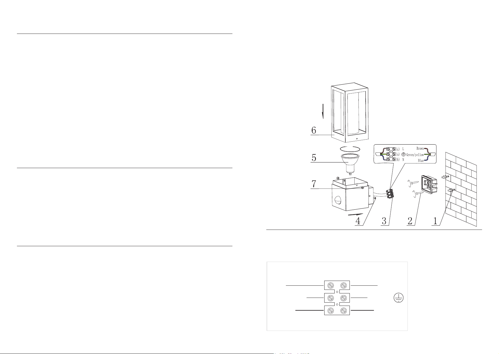
• Wire as detailed Wiring diagram.
• Refixing the light fitting over the back plate by using the screws.
• Place the bulb covers.
• Fit the appropriate bulbs into the lamp holders NOTE: Never fit bulbs of a higher wattage than specified on the label
(as this may cause overheating and damage the fitting).
• Replace fuse or circuit breaker
and switch on. Your light is
now ready for use.
Having correctly identified the wiring from your existing light fitting, pull the mains wire through the hole and connect to the
quick fit connection block inside the product in the following way:
Wiring
SUPPLY
NEUTRAL
EARTH (GREEN/YELLOW)
SWITCHED LIVE
LIGHTFITTING
BLUE (N)
BROWN (L)
GREEN/YELLOW
See Wiring Diagram


