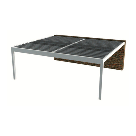
Saxun Bioclimatic Pergola P-150 User manual

ASSEMBLY INSTRUCTIONS BIOCLIMATIC PERGOLA
WITHOUT COLUMNS CUT-OUT P-150


INDEX
01 INSTALLATION 03
We do not provide the screws for fixing-anchoring to the wall and/or foundations. The fitter must choose the adequate
rod / screw / plug / nut / washer system for fixing and flushing to the foundations ad/or wall, based on the nature of
these surfaces. In any case, the screws must be in stainless steel.
1.1 ELECTRICAL PRE-INSTALLATION 03
1.2 ASSEMBLING THE PERGOLA STRUCTURE 05
1.3 INSTALLING THE PERGOLA WITHOUT COLUMNS 06
1.4 JOINING THE SURFACE MANIFOLDS IN THE OPENING AND CLOSING BEAM 07
1.5 INSTALLING THE RUBBER 08
1.6 INSTALLING “U” DRAINING PROFILE SIDE 09
1.7 INSTALLING THE SLAT 10
1.8 INSTALLING THE TRANSMISSION PLATE 13
1.9 MOTOR INSTALLATION 14
02 ELECTRICAL CONNECTIONS 15
The connection of the electrical installation must be done adhering to the current regulations for low voltage
2.1 ELECTRICAL DIAGRAM OF COMPONENTS 16
03 INSTALLING THE COLUMN CAP 16
04 SWITCHBOARD PROGRAMMING (factory set up) 17
4.1 ADVANCED MOTOR PROGRAMMING (factory set up) 17
4.2 LED LINE PROGRAMMING (factory set up) 19
4.3 TOTAL MEMORY DELETION 19
4.4 CENTRAL PROGRAMMING OF 1 MOTOR WITHOUT LED OR SENSORS 20
05 MAINTENANCE 20
Before assembling, please read the maximum tightening torque for each type of screw, as indicated in this section.
—ANNEX A - REMOVING SLATS 21
—ANNEX B - DISPOSAL OF PACKAGING AND PRODUCT AT END OF USEFUL LIFE 22
—PERGOLA ASSEMBLING CHECKLIST 23

BIOCLIMATIC PERGOLA
TOP VIEW
OPENING CLOSING
OPENING CLOSING
ATTENTION: Make sure you know which end of the left and right beam corresponds to the opening and closing. In
the figure, we show the distance from the first pre-drilled hole in the opening and in the closing.
134,00 116,00
LEFT BEAM RIGHT BEAM
OPENING BEAM
CLOSING BEAM

ASSEMBLY INSTRUCTIONS WITHOUT COLUMNS CUT-OUT P-150
3
01 INSTALLATION
1.1 ELECTRIC PRE-INSTALLATION
¡VERY IMPORTANT!
At this stage of the assembly, it is necessary to consider all the cabling required, as it will have to be taken outside the
pergola, motor, LED, Bluetooth... and the outlets must be left clear before assembly continues.
Verify the position of the LED slats in order to pre-install the cabling all the way to the holes, you must pass the LED con-
nector cables through the relevant slat hole and take them to the closing beam, then pull them out ussing some cable
glands.
It will be necessary to place a watertight box outside to house all the connections and automatic mechanisms of the per-
gola.
ATTENTION: Remember this step before continuing with the assem-
bly. For a greater safety, it will be necessary to ground the pergola.
WATERTIGHT BOX
Wiring
Motor
LED
Sound
Etc...

BIOCLIMATIC PERGOLA
LEFT BEAM
RIGHT BEAM
CLOSING BEAM
OPENING BEAM
FLAT WASHER
DIN 125 A2 M8
Code 022839
VERTICAL ANGLES FOR
THE SPECIAL P-180 BEAM
Code 050264
VERTICAL ANGLES FOR
THE SPECIAL P-180 BEAM
Code 050264
COLUMN CAP P-125x125
Code 050202
SCREW
DIN (ISO 7976) A2 M8x50
Code 050198
SCREW ULS
ISO 7380 A2 M6x16
Code 050103
SCREW ULS
ISO 7380 A2 M6x16
Code 050103
HOLDER BRACKET
COLUMN CAP
Code 050262
HOLDER BRACKET
COLUMN CAP
Code 050262
PRE-DRILLED JOINING SECTION
125x125x180
Code 050263

ASSEMBLY INSTRUCTIONS WITHOUT COLUMNS CUT-OUT P-150
5
1.2 ASSEMBLING THE PERGOLA STRUCTURE
Using the 125x125x180 pre-drilled joining sections with code: 050263, assemble the beams included in the pergola struc-
ture (opening, closing, left and right) fixing them with the screws DIN 7976 A2 M8x50 code: 050263 and the flat washers
DIN 125 A2 M8 with code: 022339, (when tightening the screws align properly the pre-drilled joining sections and the
beams).
As mentioned in the section above, remember to do this before installing the side beams, passing the cables through the
closing beam and pulling them out to complete the connections in the watertight cabinet.
Once the structure has been assembled with the pre-drilled joints, mount the vertical brackets of the P-180 beam with
special code: 050264 with the corresponding screws and washers, as shown in the pictures.
LEFT BEAM
RIGHT BEAM
CLOSING BEAM
OPENING BEAM
FLAT WASHER
DIN 125 A2 M8
Code 022839
TORNILLO
DIN (ISO 7976) A2 M8x50
Code 050198
PRE-DRILLED JOINING SECTION
125x125x180
Code 050263

BIOCLIMATIC PERGOLA
1.3 INSTALLING THE PERGOLA WITHOUT COLUMNS
In order to install the pergola without columns between walls, drill 25 mm and 12 mm through holes on the beam, with a
maximum separation of 500 mm. This will allow fixing the beam to the walls, and the holes can be drilled on the bottom
of the side beams, being covered when the “U” draining profile is mounted.
For sealing, you can also use 25 mm drilling cover caps with code: 050272 (product optional, not provided) if the holes are
located on the opening or closing beams.
If the pergola is in a dierent location, the fitter will complete the installation following the necessary safety guidelines
and using the screws and anchoring required to mount the pergola correctly, according to such location.
Perform the beam installation using the adequate screws depending on the type of wall and, in any case, always using
stainless steel screws.
To achieve an optimum operation, it is recommended to install the pergola completely level. If for draining reasons (water
outlets not performed) it was necessary to leave a slope, inclinations above 1% are not recommended.
IMPORTANT: Screws and wall anchors, not provided.
500 mm

ASSEMBLY INSTRUCTIONS WITHOUT COLUMNS CUT-OUT P-150
7
ATTENTION: Do not bypass this step, it is very important to seal the manifold joint properly (sealant provided).
1.4 JOINING THE SURFACE MANIFOLDS IN THE OPENING AND CLOSING BEAM
Apply the provided sealant between the contact sides of the OPENING and CLOSING beams and their corresponding sur-
face manifolds.
Clip the opening and closing manifolds (same profile, just in an inverted position). You will possibly need to use clamps
or wooden blocks to help you with the clipping.
Create a groove for the water run-o
at each end of both manifolds (use a
hammer and a flat screwdriver).
OPENING CLOSING
CLOSING SURFACE
MANIFOLD
OPENING SURFACE
MANIFOLD

BIOCLIMATIC PERGOLA
1.5 INSTALLING RUBBER
Installing rubber on the clippable opening gutter.
Installing rubber on the last slat.
Installed in the opposite way to the rest of lasts.
The clippable closing gutter does not have rubber.
Installing rubber on the slats (150 slat step).
OPENING CLOSING

ASSEMBLY INSTRUCTIONS WITHOUT COLUMNS CUT-OUT P-150
9
1.6 INSTALLING “U” DRAINING PROFILE SIDE
Install the “U” draining profile on the LEFT and RIGHT beams and leave it flush with the beam and columns C and D.
Check that all the “U” profile holes match the M6 machined ones on the beam. If all of them match, apply the sealant be-
tween the “U” profile and the beam after screwing the profiles with the ULS (ISO 7380) A2x16 screws.
Use the sealant provided to seal the “U” profiles to the beams and the joints that could suer water leaks.
SEALANT

BIOCLIMATIC PERGOLA
To install the slats without LED you will have a set of O-210 pivot-type caps, integrated by a 16,4x25 mm plastic cap and
a retractable stainless steel axle.
The slats with LED come already pre-instaled on one side with a hollow axle. The LED connector comes through this axle
and it has a protection spring. The O-210 retractable axle needs to be installed on the other end.
For the electrical installation of the LED slats, follow the installation instructions provided.
1.7 INSTALLING THE SLATS
Before installation of the slats, place the 16,6x11 mm anti-friction caps.

ASSEMBLY INSTRUCTIONS WITHOUT COLUMNS CUT-OUT P-150
11
Start installing the slats from the opening side and from the top part of the pergola. Insert the slat axle into the left beam,
lower the right side at the same time you insert the retractable axle into the end cap and insert it into the anti-friction cap
of the right beam, so the slat is finally in place.
ATTENTION: Pay attention when installing the slats so there are no errors or confusion in their placement, opening,
closing, LED slats, etc.
If it was necessary to remove any of the slats, follow the steps described in annex A.

BIOCLIMATIC PERGOLA
When reaching a hole for LED slats, connect the connector and insert it into the beam (as shown in the images below).
As for the other slats, the installation is the same, inserting the connector axle into the beam with the LED installation and
the retractable axle into the other beam.

ASSEMBLY INSTRUCTIONS WITHOUT COLUMNS CUT-OUT P-150
13
1.8 INSTALLING THE TRANSMISSION PLATE
With the slats already in the structure, install the two transmission plates in the slat end caps. One of the slats will include
an integrated support with a motor fixing stud. It is necessary to know the side of the pergola where the motor will be
installed, so the plate can be mounted on that side.
Install the two plates simultaneously if possible. Start by fixing the first, the last and the centre slats to the transmission
plate. This facilitates the rest of the installation.
Join the plates to the end caps with their corresponding ULS (ISO 7380) A2 M6x16 screws, 6,3 mm rimmed plastic caps
and M6 DIN 985 nut.
ULS (ISO 7380) A2 M6x16
Code 051103
NUT M6 A2 DIN 985
Code 051048
RIMMED CAP 6,3
Code 051033
TRANSMISSION PLATE
ATTENTION: When installing the plate in the slats, do not tighten too much the screw nuts, so they are set without
tightening. Thus the plate can perform manually the opening and closing movements with no friction whatsoever.

BIOCLIMATIC PERGOLA
1.9 MOTOR INSTALLATION
The motor location will be placed by default on the left beam and transmission plate (unless specified otherwise in the
manufacturing order). Similarly, the threaded holes for the motor bracket (1) will be on the beam and the transmisison
plate will include the motor operation delta plate with its stud (2).
ATTENTION: The threaded holes in the beam (1) may vary depending on the motor bracket used, but they will al-
ways be adjusted to it, regardless of the typology.
Steps to join the motor to the transmission plate.
1Insert the tip of the motor piston rod into the operation delta plate stud.
2Mount the nut on the transmission plate stud so the motor does not slip out.
2
1

ASSEMBLY INSTRUCTIONS WITHOUT COLUMNS CUT-OUT P-150
15
02 ELECTRICAL CONNECTIONS
The connection of the electrical installation must be in compliance with the rules and regulations of each country (Low
voltage electrotechnical regulation).
The perimeter cabling for the electrical and sound installations will be passed through the beam and column spaces,
install the watertight cabinet on the outside in order to connect the power supply, so the pergola will only be able to reach
a voltage of 24 V.
The motor cable will be inserted into the beam with a gland located
next to the motor.
The engine cables, LED, music, etc., will exit the closing beam and
will be taken to the watertight cabinet.
Complete the electric connections of the pergola according to the
instructions and considering that both the motor and the LEDs run
with a 24 V voltage. For this reason, it is necessary to use the power
source, (installed at the end of the pergola).
For cables entering the switchboard:
- Cut the central part of the membrane.
- Insert the cable carefully to prevent any
water filtration.
ATTENTION: For greater safety, it is necessary to ground the pergola.
ATTENTION: The motor bracket could be dierent to the one in the image; however, the holes pre-drilled on the
beam will be the correct ones for the bracket holding the motor at any time.
3Move the motor opening the pergola until the bracket can be screwed on the beam threaded holes.

BIOCLIMATIC PERGOLA
03 INSTALLING THE COLUMN CAP
After the electric connections are completed, installing
the column caps is the last stage left. To do this, the caps
will be screwed to the inner reinforcements using the ULS
(ISO 7380) A2 M6x16 mm screws.
When all the column caps have been installed, it will be
necessary to seal their joints with the sealant provided,
as mentioned before, one of the caps has 3 glands to take
the cables out to the switchboard.
1POWER SUPPLY 24 Vdc +
2POWER SUPPLY 24 Vdc -
3S1 MOTOR +
4S1 MOTOR -
5S2 LED -
6S2 LED +
7RAIN SENSOR
8RAIN SENSOR
1+ POSITIVE 24V
2- NEGATIVE 24V
3MOTOR +
4MOTOR -
2.1 ELECTRICAL DIAGRAM COMPONENTS
1 motor switchboard with LED and with sensors.
1 motor switchboard without LED and without sensors.
+ +
- -
3 1
4 2
PROG. POWER SUPPLY 24V
Power
DINUY
IN
ON
S1
S2
ON
OFF
OUT LED
RAIN SENSOR
24 Vdc
POWER
SUPPLY
24 Vdc 230V
MOTOR
L
N
31 2 7 8
1 2 3 4
5
4
6
+
+
+
+
+ +
+
-
-
-
- -
-
-
PROG.

ASSEMBLY INSTRUCTIONS WITHOUT COLUMNS CUT-OUT P-150
17
04 SWITCHBOARD PROGRAMMING (factory set up)
4.1 ADVANCE MOTOR PROGRAMMING (factory set up)
1Press and hold PROG on the electronic unit for over 2
seconds until the S1 LED flashes, then release.
(S1 output set up)
PROG.
S1
S2 >2s
2Select the desired output, S1 or S2
(Desired channel).
PROG.
S1
S2
3Select the profile desired for the motor.
4Press Λ+V simultaneously.
(Set up channel)
my
<
<
5Check the rotating direction Λ=open / V=close.
If the rotation is not correct, reerse the direction by
pressing my for over 5 seconds.
(Required output setting up).
Check the direction of rotation again.
my
<
<
>5s
6Open the pergola (press and release Λ).
my
<
<
7Confirm the opening position by pressing V+my simulta-
neously
(The pergola will open automatically)
my
<
<
CONFIGURED
CONFIGURED
CONFIGURED
CONFIGURED
OPEN
CLOSE
AUTO

BIOCLIMATIC PERGOLA
8Stop de movement pressing my.
my
<
<
9Close the pergola (press and release V).
my
<
<
10 Confirm the closing position by pressing Λ+my simul-
taneously.
(The pergola will open automatically)
my
<
<
11 Stop the movement pressing my.
my
<
<
12 Open the pergola to the position desired in case of
snow.
(Press and release Λ+V).
my
<
<
13 Confirm the position desired in case of snow by press-
ing and holding my for over 2 seconds.
(Required output set up).
my
<
<
>2s
14 Press PROG. briefly at the back of the remote.
(Required output set up).
STOP
CLOSE
STOP
OPEN
CONFIGURED
CONFIGURED
OPEN
AUTO
Other manuals for Bioclimatic Pergola P-150
1
This manual suits for next models
1
Table of contents
Other Saxun Lawn And Garden Equipment manuals