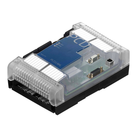
Hardware Manual for the PCD2.M5 Series│Document 26/856; Version EN 12│2014-07-24
Saia-Burgess Controls AG
PCD2.M5_
Contents
0-3
0
5 PCD2.M5xx0 Communication interfaces
5.1 Onboard interfaces ......................................................................................... 5-2
5.2 Plug-in communication interfaces ................................................................... 5-2
5.3 Onboard interfaces ......................................................................................... 5-3
5.3.1 PGUconnector(PORT# 0)(RS-232)forconnectingprogrammingdevices... 5-3
5.3.2 PGUconnection(PORT# 0)(RS-232)ascommunicationinterface ............... 5-4
5.3.3 PGUconnection(PORT# 0)(RS-485)ascommunicationinterface ............... 5-5
5.3.4 USB port as PGU interface ............................................................................. 5-6
5.3.5 D-Sub x1 S-Net/MPI ....................................................................................... 5-7
5.4 Plug-in interface modules - Slots A1 and A2................................................... 5-8
5.4.1 RS-485 / 422withPCD7.F110,Port#1 & Port#2 ............................................. 5-8
5.4.2 RS-232withPCD7.F121,Port#1 & Port#2..................................................... 5-10
5.4.3 CurrentloopwithPCD7.F130,Port#1&Port#2 ............................................. 5-11
5.4.4 RS-485withPCD7.F150,Port#1 & Port#2..................................................... 5-13
5.4.5 MP-BuswithPCD7.F180,Port#1&Port#2 .................................................... 5-15
5.5 Serial interfaces on I/O module slots 0 - 3 ...................................................... 5-16
5.5.1 GeneralremarksonthePCD2.F2xxx............................................................. 5-16
5.5.2 Communication ports on the PCD2.M5_ ........................................................ 5-16
5.5.3 Module overview ............................................................................................. 5-17
5.5.4 Portx.0:RS-422/RS-485onthemodulPCD2.F2100................................... 5-21
5.5.5 Portx.0:RS-232onthemodulPCD2.F2210(formodem) ............................. 5-22
5.5.6 Portx.0:BelimoMP-BusonmodulePCD2.F2810 ......................................... 5-23
5.6 Modem module for I/O module socket ............................................................ 5-24
5.7 Communication on Slot C ............................................................................... 5-25
5.7.1 CANbus,modulePCD7.F7400...................................................................... 5-26
5.7.2 ProbusDPMaster,modulePCD7.F7500 ..................................................... 5-27
6 Input/output (I/O) modules
6.1 Module overview ............................................................................................. 6-1
6.1.1 Power consumption of PCD2 input/output modules ....................................... 6-5
6.1.2 Capacity of basic units .................................................................................... 6-5
6.2 Digital input modules....................................................................................... 6-6
6.2.1 PCD2.E11x, 8 digital inputs ............................................................................ 6-7
6.2.2 PCD2.E160/161, 16 digital inputs, ribbon cable connector............................. 6-9
6.2.3 PCD3.E165/166, 16 digital inputs, cage clamp terminal connectors .............. 6-12
6.3 Digital input modules, electrically isolated ...................................................... 6-14
6.3.1 PCD2.E500, 6 digital inputs for 115 - 230 VAC............................................... 6-15
6.3.2 PCD3.E61x, 8 digital inputs, electrically isolated ............................................ 6-17
6.4 Digital output modules .................................................................................... 6-19
6.4.1 PCD2.A300, 6 digital outputs for 2 A each...................................................... 6-20
6.4.2 PCD2.A400, 8 digital outputs for 0.5 A each................................................... 6-22
6.4.3 PCD2.A460, 16 digital outputs for 0.5 A each, with ribbon connector............. 6-24
6.4.4 PCD2.A465, 16 digital outputs for 0.5 A each................................................. 6-27
6.5 Digital output modules, electrically isolated .................................................... 6-29
6.5.1 PCD2.A200, 4 relays with make contacts, with contact protection................. 6-30
6.5.2 PCD2.A210, 4 relays with break contacts, with contact protection................. 6-32
6.5.3 PCD2.A220, 6 relays with make contacts, without contact protection............ 6-34
6.5.4 PCD2.A250, 8 relays with make contacts, without contact protection............ 6-36
6.5.5 PCD2.A410, 8 digital outputs for 0.5 A each, electrically isolated................... 6-38
