ScanTools ECUsim 5100 User manual

User Guide
ECUsim™5100
Professional Multiprotocol 3-PIM
OBD-II ECU Simulator

2 ECUsim™ 5100 User Guide
Information contained in this document is subject to change without notice.
Trademarks are property of their respective owners.
© 2010 ScanTool.net LLC. All rights reserved.
Printed in the United States of America.

ECUsim™ 5100 User Guide 3
Table of Contents
1.0 Overview ...................................................................................................................4
1.1 General Features........................................................................................................... 5
1.2 Package Contents......................................................................................................... 5
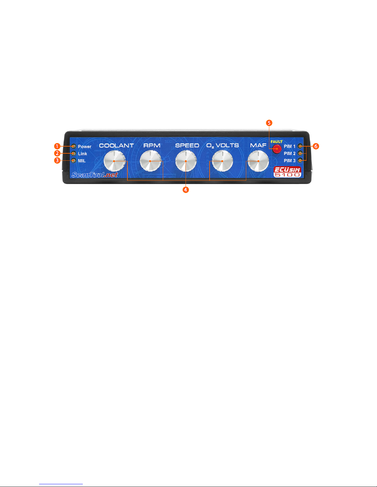
2.0 User Interface...........................................................................................................6
2.1 Front Panel...................................................................................................................... 6
2.2 Back Panel........................................................................................................................ 7
3.0 Basic Operation.......................................................................................................8
3.1 Setup.................................................................................................................................. 8
3.2 Using the Simulator..................................................................................................... 8
4.0 UART Communication ..........................................................................................9
4.1 Installing USB Drivers.................................................................................................. 9
4.2 Terminal Setup .............................................................................................................. 9
5.0 PIM Configuration............................................................................................... 10
5.1 Supported Commands.............................................................................................10
6.0 Advanced Operation .......................................................................................... 11
6.1 ISO 9141-2 and ISO 14230-4 (5 Baud Init) ........................................................11
6.2 ISO 14230-4 (Fast Init)...............................................................................................12
6.3 SAE J1850 and ISO 15765-4....................................................................................12
6.4 Monitoring OBD Traffic ............................................................................................12
6.5 Status Messages..........................................................................................................13
7.0 Virtual ECUs........................................................................................................... 14
7.1 Engine Control Module (ECM)...............................................................................15
7.1.1 ECM: Mode 1 ....................................................................................................15
7.1.2 ECM: Mode 2 ....................................................................................................17
7.1.3 ECM: Mode 3 ....................................................................................................17
7.1.4 ECM: Mode 4 ....................................................................................................17
7.1.5 ECM: Mode 7 ....................................................................................................18
7.1.6 ECM: Mode 9 ....................................................................................................18
7.1.7 ECM: Mode A....................................................................................................18
7.2 Transmission Control Module (TCM) ..................................................................19
7.2.1 TCM: Mode 1 ....................................................................................................19
7.2.2 TCM: Mode 3 ....................................................................................................19
7.2.3 TCM: Mode 4 ....................................................................................................19
7.2.4 TCM: Mode 7 ....................................................................................................20
7.3 ABS Control Module (ABS)......................................................................................20
7.3.1 ABS: Mode 1......................................................................................................20
7.3.2 ABS: Mode 4......................................................................................................20
7.3.3 ABS: Mode 7......................................................................................................20
8.0 Firmware Updates............................................................................................... 21
Appendix A: Specifications....................................................................................... 22
Appendix B: Revision History .................................................................................. 22
Appendix C: Warranty................................................................................................ 22
Appendix D: Contact Information.......................................................................... 22

4 ECUsim™ 5100 User Guide
1.0 Overview
ECUsim 5100 is a small, lightweight, benchtop simulator that can be used for
testing and development of OBD devices and software. It supports all legislated
OBD protocols, fixed and user adjustable parameter IDs (PIDs), diagnostic
trouble codes (DTCs), freeze frames, and many other SAE J1979 services.
The unit has five knobs assigned to common PIDs, a “fault event” button, and
indicator lights for power, connection, and MIL (Malfunction Indicator Light).
Physical connection to the scan tool is made through a standard SAE J1962
female connector.
The simulator can accept from one to three plug-in modules (PIMs), each
configured for a different OBD protocol. The user is able to select any one of
the three protocols using a three position switch, or make them active at the
same time.
ECUsim 5100 features a USB connection which can be used to configure the
PIMs and to monitor OBD traffic.

ECUsim™ 5100 User Guide 5
1.1 General Features
•Support for all legislated OBD-II protocols:
oSAE J1850 PWM
oSAE J1850 VPW
oISO 9141-2
oISO 14230-4 (KWP2000)
oISO 15765-4 (CAN 250/500kbps, 11/29 bit)
•Functional and physical addressing
•Three PIM slots
•Each PIM supports three virtual ECUs: ECM, TCM, and ABS
•Five knobs assigned to frequently used PIDs:
oCoolant Temperature
oEngine Speed (RPM)
oVehicle Speed
oOxygen Sensor Voltage
oMass Airflow (MAF)
•Fixed SAE J1979 modes and PIDs
•“MIL”, “Link” and “Power” indicators
•“FAULT” button
•USB connection for PIM configuration and OBD traffic monitoring
•On-the-fly OBD protocol switching
•Standard J1962F connector
•Firmware upgradeable
1.2 Package Contents
•ECUsim 5100 unit (with 1, 2, or 3 installed PIMs)
•110/220 VAC to 12 VDC switching power supply
•US style power cable
•OBD connector dust cover
•USB cable

6 ECUsim™ 5100 User Guide
2.0 User Interface
ECUsim 5100 can be used as a stand alone simulator, or in conjunction with a
PC. It features a number of interface elements on both the front and back of
the unit.
2.1 Front Panel
1. Power LED
2. Link LED
The function of this LED depends on the protocol in use:
a. ISO 9141-2 and ISO 14230-4 protocols: the LED is on while at
least one ECU is initialized. The LED dims when an OBD
message is received.
b. J1850 and CAN protocols: the LED blinks when an OBD
message is received.
3. Malfunction Indicator Light
4. Knobs assigned to the five commonly used Mode 1 PIDs.
5. FAULT button
When pressed, the following happens:
a. Set MIL and number of stored DTCs (Mode 1, PID 01)
b. Generate pending, stored, and permanent* DTCs
c. Generate freeze frame data
6. PIM indicators
a. OFF: PIM not present
b. RED: PIM is present, not selected
c. GREEN: PIM is active
*SAE J1979 defines permanent DTCs only for ISO 15765-4 (CAN)

ECUsim™ 5100 User Guide 7
2.2 Back Panel
1. PIM Select switch
2. USB connector
3. Diagnostic Link Connector (DLC)
4. Configuration DIP switch
a. PIM ALL. Down position: makes all three PIMs active at the
same time. Up position: PIM selection is controlled by the PIM
Select switch
b. 5BAUD/FAST. Selects the type of initialization for ISO 14230-4.
Down: 5 baud init, up: fast init.
c. 11/29 BIT. Selects the CAN frame ID type. Down: 11-bit, up:
29-bit.
d. 250K/500K. Selects the CAN baud rate. Down: 250 kbps, up:
500 kbps.
5. Power jack (12 VDC)
Use only the provided power supply to power the simulator.
Using a different power supply may cause permanent damage
which is not covered under the warranty.

8 ECUsim™ 5100 User Guide
3.0 Basic Operation
ECUsim is configured at the factory according to your specifications (number of
PIMs, assigned protocols) and is ready to be used out of the box. For custom
configuration, see Section 5.0, PIM Configuration.
3.1 Setup
To set up the simulator, follow these steps:
1. Use the Configuration DIP switch to set the desired options.
2. Plug the power supply into an available electric outlet.
3. Plug the 12 volt end of the power supply into the power jack of the
simulator.
4. Select the desired PIM using the PIM Select switch. The corresponding
LED on the front panel will turn green.
5. Connect the OBD connector of your OBD tester or OBD interface to
the DLC.
3.2 Using the Simulator
Once the simulator is set up and configured, you can use the PIM Select switch
on the back of the unit, to switch between PIM1, PIM2, and PIM3. When you
switch to a new PIM, two things should happen:
1. The corresponding PIM indicator LED should change from red to
green.
2. The Power, Link, and MIL LEDs will turn on and off in sequence, as the
PIM starts up.
To generate a malfunction event, press the FAULT button.
The Link light should be flashing or dimming as the messages are exchanged
between the tester and the simulator.
For more details, see the respective descriptions in Section 2.1.

ECUsim™ 5100 User Guide 9
4.0 UART Communication
ECUsim 5100 features a USB connection. On a Windows or Linux PC, the drivers
create virtual COM ports which allow communication using any suitable serial
port terminal (e.g., HyperTerminal).
Set PIM ALL switch to OFF
In order to communicate with a PIM, the PIM ALL switch must be
in the “up” (off) position.
4.1 Installing USB Drivers
To communicate with the ECUsim, make sure it is powered on, and connect it
to any available USB port. If the operating system does not find & install the
drivers automatically, you can download them from FTDI’s website.
FTDI Virtual Com Port Drivers
http://www.ftdichip.com/Drivers/VCP.htm
4.2 Terminal Setup
Almost any serial port terminal emulation program can be used to
communicate with the ECUsim. Some of the popular terminals include the
HyperTerminal, RealTerm, and TeraTerm.
The default communication settings are:
Baud rate: 115200 bps
Data bits: 8
Parity: none
Stop bits: 1
Turn off local echo
ECUsim echoes back what you type, so you may want to turn off
local echo to avoid “seeing double.”

10 ECUsim™ 5100 User Guide
5.0 PIM Configuration
On startup or reset, the PIM prints the configuration summary that looks similar
to this:
STSP300v2.1.0
(C)2010ScanTool.net,LLC
OBDProtocolJ1850PWM
ECU0Address10
ECU1Address18
ECU2Address28
Press the Enter key to display the command prompt:
>
The PIM is now ready to accept user commands.
5.1 Supported Commands
The following is a summary of currently supported commands:
MON 0/1 OBD bus monitoring off/on
RESET Reboot the PIM
SP xSet OBD protocol
MON 0/1
Turn OBD bus monitoring off (0) or on (1). On power up, OBD monitoring is on
by default. Under certain conditions, turning off bus monitoring can decrease
ECU response time.
RESET
Reboot the PIM. Useful for reading new configuration from the DIP switch.

ECUsim™ 5100 User Guide 11
SP x
Switch protocol to ‘x’, where ‘x’ is the protocol number.
Protocol
Number
Protocol
0 none
1 J1850 PWM
2 J1850 VPW
3 ISO 9141-2
4 ISO 14230-41
5 ISO 15765-42
1 The 5BAUD/FAST switch determines the type of initialization (5 baud or fast).
2 Baud rate and CAN ID type are controlled by the 250K/500K and 11/29 BIT switches.
When this command is executed, the PIM closes the currently active protocol,
reboots, and prints the configuration summary for the newly selected protocol.
6.0 Advanced Operation
This section describes the operation of the simulator in different protocol
modes. It assumes that the simulator is connected to a PC running terminal
emulation software.
6.1 ISO 9141-2 and ISO 14230-4 (5 Baud Init)
After switching to the ISO 9141-2 protocol (or ISO 14230-4 with 5 baud init
option) the PIM will print the following status message:
<WAITINGFOR5BAUDINIT>
It will not respond to any requests until the bus is initialized. After a successful
initialization sequence, the PIM will print:
<5BAUDINIT:OK>
At this point, the virtual ECUs will start responding to OBD requests. However, if
five seconds pass without a supported request (or a keep-alive message) being
received, the ECUs will time out and the PIM will go back to waiting for
initialization:
<ALLECUSTIMEDOUT>
<WAITINGFOR5BAUDINIT>

12 ECUsim™ 5100 User Guide
6.2 ISO 14230-4 (Fast Init)
After switching to the ISO 14230-4 protocol with fast init option, the PIM will
print the following status message:
<WAITINGFORFASTINIT>
It will not respond to any requests until the bus is initialized. After a successful
initialization sequence, the PIM will print:
<FASTINIT:OK>
At this point, the virtual ECUs will start responding to OBD requests. However, if
five seconds pass without a supported request (or a keep-alive message) being
received, the ECUs will time out and the PIM will go back to waiting for
initialization:
<ALLECUSTIMEDOUT>
<WAITINGFORFASTINIT>
6.3 SAE J1850 and ISO 15765-4
Protocols 1, 2, and 5 do not require initialization. Once the PIM reboots after
the set protocol command and prints the configuration summary, it will
immediately start listening to, and responding to OBD requests.
6.4 Monitoring OBD Traffic
By default, each PIM prints incoming and outgoing OBD messages including
the message headers, but without the checkbyte. Here is an example of
communication between a tester and the PIM on J1850 PWM:
Rx:616AF10100
Tx:416B104100BE1B3013
Tx:416B18410088180010
Tx:416B28410000080010
J1850 VPW, ISO 9141-2, and ISO 14230-4 messages follow the same format:
each message has a three byte header followed by data bytes. ISO 15765-4
messages have either 11-bit or 29-bit headers. So a typical 11-bit exchange
would appear as follows:
Rx:7DF0100
Tx:7E84100BE1B3013

ECUsim™ 5100 User Guide 13
Tx:7E9410088180010
Tx:7EA410000080010
Same exchange on 29-bit CAN:
Rx:18DB33F10100
Tx:18DAF1104100BE1B3013
Tx:18DAF118410088180010
Tx:18DAF128410000080010
Monitoring can be turned off using the MON 0 command to increase the
refresh rate. To enable monitoring again, issue MON 1.
6.5 Status Messages
<UART TX OVERFLOW>
UART transmit buffer overflow detected.
<MALFUNCTION EVENT>
User pressed the FAULT button.
<WAITING FOR 5 BAUD INIT>
The simulator is waiting for an ISO 9141-2 or ISO 14230-4 5 baud initialization
sequence.
<WAITING FOR FAST INIT>
The simulator is waiting for an ISO 14230-4 fast initialization sequence.
<5 BAUD INIT: OK>
Detected a successful 5 baud initialization sequence.
<FAST INIT: OK>
Detected a successful ISO 14230-4 fast initialization sequence.
<ALL ECUS TIMED OUT>
All virtual ECUs had timed out, because a supported request had not been
received within P3MAX.

14 ECUsim™ 5100 User Guide
7.0 Virtual ECUs
There are three virtual ECUs: Engine Control Module (ECM), Transmission
Control Module (TCM), and Anti-lock Braking System module (ABS). The ECUs
support both physical and functional addressing, as specified in the SAE J2178,
Part 1 and ISO 15765-4 documents.
Functional address supported by the ECUs depend on the selected protocol
and, in the case of ISO 15765-4, the ID type (11-bit or 29-bit):
Protocol(s) Functional
Address
J1850 PWM
J1850 VPW
ISO 9141-2
$6A
ISO 14230-4
ISO 15765-4 (29-bit)
$33
ISO 15765-4 (11-bit) $7DF
Physical address assignments also depend on the protocol and CAN ID in use,
and are summarized in the following table:
ECU ISO 15765-4
(11-bit ID)
Other
Protocols
Engine Control Module (ECM) $7E0 $10
Transmission Control Module (TCM) $7E1 $18
ABS Module (ABS) $7E2 $28
29-bit ISO 15765-4, SAE J1850, ISO 9141-2, and ISO 14230-4 addresses follow
the physical address assignments outlined in SAE J2178, Part 1.

ECUsim™ 5100 User Guide 15
7.1 Engine Control Module (ECM)
The following summarizes modes, PIDs, and Infotypes supported by the PCM.
7.1.1 ECM: Mode 1
PID Description Fixed/Variable Hex Value Scan Tool
Display
00 Supported PIDs
01-1F
fixed BE1B3013
01 Monitors/DTC
Count/MIL
fixed10007EF80
See PID 01
Monitors table
03 Fuel System
Status
fixed 0201 Closed Loop/
Open Loop
04 Calculated Load
Value
fixed 32 20%
05 Engine Coolant
Temperature
variable, knob #1 00 to FF -40°C to +215°C
06 Short Term Fuel
Trim: Bank 1
fixed 3C -53.1%
07 Long Term Fuel
Trim: Bank 1
fixed 46 -45.3%
0C Engine RPM variable, knob #2 0000 to
FFFF
0.00 to
16383.75 rpm
0D Vehicle Speed
Sensor
variable, knob #3 00 to FF 0 to 255 km/h
0F Intake Air
Temperature
fixed 41 25°C
10 Mass Air Flow variable, knob #4 0000 to
FFFF
0.00 to
655.35 g/s
13 Location of
Oxygen Sensors
fixed 01 Bank 1, Sensor 1
14 Oxygen Sensor
Voltage
variable, knob #5 00 to FF 0.000 to 1.275 V
14 Short Term Fuel
Trim
fixed 80 0%
1C OBD Type fixed 01 OBD II (CARB)
1F Time Since
Engine Start
fixed 0258 600 seconds
1When FAULT button is pressed, the MIL bit and DTC count bits change.

16 ECUsim™ 5100 User Guide
20 Supported PIDs
21-3F
fixed 80022001
21 Distance Traveled
While MIL is
Activated
fixed 03E8 1000 km
2F Fuel Level Input fixed 80 50.2%
33 Barometric
Pressure
fixed 64 100 kPa
40 Supported PIDs
41-5F
fixed 44000000
42 Control Module
Voltage
fixed 2EE0 12 V
46 Ambient Air
Temperature
fixed 3C 20°C
7.1.1.1 PID 01 Monitors
Continuous Monitors
Monitor Supported Ready
Misfire Yes Yes
Fuel System Yes Yes
Comprehensive Component (CCM) Yes Yes
Compression Ignition Supported No
Non-continuous Monitors
Monitor Supported Ready
Catalyst Yes Yes
Heated Catalyst Yes Yes
Evaporative System Yes Yes
Secondary Air System Yes Yes
A/C System Refrigerant No
Oxygen Sensor Yes Yes
Oxygen Sensor Heater Yes Yes
EGR System Yes No

ECUsim™ 5100 User Guide 17
7.1.2 ECM: Mode 2
When the user generates a malfunction event, the following freeze frame is
stored:
PID Description Hex Value Scan Tool
Display
00 Supported PIDs 01-1F 48180000
02 DTC that Caused F.F. Storage 0100 P0100
05 Engine Coolant Temperature 8C 100°C
0C Engine RPM 4E20 5000 rpm
0D Vehicle Speed Sensor 78 120 km/h
7.1.3 ECM: Mode 3
When the MIL is on, Mode 3 reports six DTCs:
P0100
P0200
P0300
C0300
B0200
U0100
7.1.4 ECM: Mode 4
Issuing Mode 4 request performs the following operations:
Turn off MIL (Mode 1, PID 1)
Erase Freeze Frame (Mode 2)
Erase stored DTCs (Mode 3)
Erase pending DTCs (Mode 7)

18 ECUsim™ 5100 User Guide
7.1.5 ECM: Mode 7
When the MIL is on, Mode 7 reports four pending DTCs:
P0107
P0207
P0307
C0307
7.1.6 ECM: Mode 9
The following infotypes are supported:
Infotype Description Scan Tool Display
00 Supported Infotypes
01 VIN Message Count*
02 VIN 1G1JC5444R7252367
03 Calibration ID message count*
04 Calibration ID JMB*36761500
05 CVN Message Count*
06 CVN 1791BC82
0A ECUNAME ECU1-EngineControl
* Message count infotypes are not supported in ISO 15765-4, per SAE J1979.
7.1.7 ECM: Mode A
After the first MIL event (user pressed the “MIL” button), Mode A reports one
permanent DTC:
P1234
This mode is only available for ISO15765-4.
SAE J1979 does not define Mode A for the SAE J1850, ISO 9141-2,
or ISO 14230-4 protocols.
Permanent DTCs cannot be erased using a Mode 04 request.
To erase this DTC, you must reset the PIM by issuing the RESET
command, momentarily deselecting it using the PIM Select switch,
or power cycling the simulator.

ECUsim™ 5100 User Guide 19
7.2 Transmission Control Module (TCM)
The following summarizes modes, PIDs, and Infotypes supported by the TCM.
7.2.1 TCM: Mode 1
PID Description Fixed/Variable Hex Value Scan Tool
Display
00 Supported PIDs
01-1F
fixed 88180010
01 Monitors/DTC
Count/MIL
fixed*00000000 All monitors not
supported
05 Engine Coolant
Temperature
variable, knob #1 00 to FF -40°C to +215°C
0C Engine RPM variable, knob #2 0000 to
FFFF
0.00 to 16383.75
rpm
0D Vehicle Speed
Sensor
variable, knob #3 00 to FF 0 to 255 km/h
1C OBD Type fixed 01 OBD-II (CARB)
*When the FAULT button is pressed, the MIL bit gets set, and the DTC count bits change to reflect
the number of stored DTCs.
7.2.2 TCM: Mode 3
When MIL is on, Mode 3 reports one DTC:
P0101
7.2.3 TCM: Mode 4
Issuing Mode 4 request performs the following operations on the TCM:
Erase stored DTCs (Mode 3)
Erase pending DTCs (Mode 7)

20 ECUsim™ 5100 User Guide
7.2.4 TCM: Mode 7
When MIL is on, Mode 7 reports two DTCs:
P0102
U1600
7.3 ABS Control Module (ABS)
The following summarizes modes, PIDs, and Infotypes supported by the ABS.
7.3.1 ABS: Mode 1
PID Description Fixed/Variable Hex Value Scan Tool
Display
00 Supported
PIDs 01-1F
fixed 00080010
0D Vehicle Speed
Sensor
variable, knob #3 00 to FF 0 to 255 km/h
1C OBD Type fixed 01 OBD-II (CARB)
7.3.2 ABS: Mode 4
Issuing Mode 4 request performs the following operations on the ABS:
Erase pending DTCs (Mode 7)
7.3.3 ABS: Mode 7
When MIL is on, Mode 7 reports one DTC:
B2245
Table of contents