Scantronic KEY-K01 User manual

Scantronic
12V
0V
A
B
LED
0V
12V
OP
A
B
ADDR 4
ADDR 3
ADDR 2
BRIGHT
TERM
D1
D0
0V
12V
Z1
Z2
KEY-K01/KEY-KP01/KEY-KPZ01
UK Installation Instructions
FR Guide d’installation
NL Installatiehandleiding
Figure 1. Key usage / Abb. 1. Verwendung derTasten / Figure 1. Fonction des touches / Figura 1. Uso dei tasti / Afbeelding 1. Toetsgebruik
1
Programmable keys / ProgrammierbareTasten / Touches programmables /Tasti programmabili / Programmeerbare toetsen
Hold-up keys / Überfalltasten / Touches Agression /Tasti allarme panico / Overval-toetsen
LCD display / LCD-Display / Afficheur LCD / Display LCD / LCD-scherm
Programming keys / Programmiertasten /Touches de programmation /Tasti di programmazione / Programmeertoetsen
Navigation key / Navigationstaste /Touche de navigation /Tasto di navigazione / Navigatietoets
Unset key / Deaktivierungstaste / Touche de désarmement /Tasto disinserimento / Uitschakeltoets
Figure 2. Removing the cover
Abb. 2. Die Abdeckung entfernen
Figure 2. Dépose du couvercle
Figura 2. Rimozione del coperchio
Afbeelding 2. Deksel verwijderen
Cable-entry holes (also on each side) / Öffnungen für Kabeleingang (auch an jeder Seite) / Trous de
passage de câble (de chaque côté) / Fori di ingresso cavi (anche su ciascun lato) / Kabelopening
(ook aan weerskanten)
Use the supplied 3mm x 19mm (No4) screw for the tamper block.
Verwenden Sie die im Lieferumfang enthaltene Schraube (3 mm x 19 mm,
Nr. 4) für den Sabotageblock.
Utilisez la vis 3 mm x 19 mm (No4) fournie pour le bloc d’autoprotection.
Utilizzare la vite di 3 mm x 19 mm (N. 4) in dotazione per il blocco
antimanomissione.
Gebruik de meegeleverde 3 mm x 19 mm (Nr. 4) schroef als
sabotage-beveiliging.
Minimum 3 off 4mm x 25mm (No8) countersunk screws
Verwenden Sie mindestens drei Senkkopfschrauben (4mm x 25mm, Nr.8)
Au moins 3 vis à tête fraisée 4mm x 25mm (No 8)
Minimo 3 viti svasate di 4 mm x 25 mm (N. 8)
Minimaal 3 van 4 mm x 25 mm (Nr. 8) verzonken schroeven
Figure 3. Mounting the backplate / Abb. 3. Die Rückplatte montieren / Figure 3. Montage de la plaque
arrière / Figura 3. Montaggio della piastra posteriore / Afbeelding 3. Grondplaat monteren
DE Installationsanweisungen
IT Istruzioni per l’installazione
Figure 4. Keypad PCB / Abb. Keypad-Leiterplatte / Figure 4. Carte électronique du clavier (PCB) / Figura 4. PCB tastiera /
Afbeelding 4. Printplaat toetsenbord
This product must be installed and maintained only by qualified service personnel. /
Dieses Produkt darf nur von qualifiziertem Servicepersonal installiert und gewartet werden. /
Ce produit doit être installé et entretenu par un technicien qualifié. /
Questo prodotto deve essere installato e sottoposto a manutenzione solo da personale di servizio qualificato. /
Dit product moet steeds door gekwalificeerde vakmensen worden geïnstalleerd en onderhouden.
Bus
Bus device / Busgerät / Dispositif de
bus / Dispositivo bus / Busapparaat
Open-collector output (KEY-KPZ01 only) / Open-Kollektor-
Ausgang (nur KEY-KPZ01) / Sortie à collecteur ouvert
(KEY-KPZ01 uniquement) / Uscita open-collector (solo
KEY-KPZ01) / Open-collector uitgang (alleen KEY-KPZ01)
Address links / Adressverbindungen /
Cavaliers d’adressage / Collegamenti indirizzi /
Adresverbindingen
Brightness/ Helligkeit / Luminosité /
Luminosità / Helderheid
RS485 termination / RS485-Abschluss / Raccordement
RS485 /Terminazione RS485 / RS485-afsluiting
Volume / Lautstärke /
Volume / Volume / Volume
Blue/Blau/Bleu/Blu/Blauw
White/Weiß/Blanc/Bianco/Wit
Green/Grün/Vert/Verde/Groen
Red/Rot/Rouge/Rosso/Rood
Black/Schwarz/Noir/Nero/Zwart
KEY-EP (KEY-KP01 and KEY-KPZ01 only) /
KEY-EP (nur KEY-KP01 und KEY-KPZ01) /
KEY-EP (KEY-KP01 et KEY-KPZ01 uniquement) /
KEY-EP (solo KEY-KP01 e KEY-KPZ01) /
KEY-EP (alleen KEY-KP01 en KEY-KPZ01)
Zones 1-2 (KEY-KPZ01 only) /
Zonen 1-2 (nur KEY-KPZ01) /
Zones 1-2 (KEY-KPZ01 uniquement) /
Zone 1-2 (solo KEY-KPZ01) /
Zones 1-2 (alleen KEY-KPZ01)

Page 2
UK
Introduction
The KEY-K01, KEY-KP01 and KEY-KPZ01 are wired
keypads for use with i-on intrusion systems.
Features:
•
Allows installers to access the Installer menu,
and users to set/unset the system or access
the User menu.
•
Built-in proximity reader, and terminals for an
external KEY-EP proximity reader (KEY-KP01
and KEY-KPZ01 only).
•
Two zones and a programmable output (KEY-
KPZ01 only).
•
Backlit display and keys.
•
Navigation key for menus, with built-in alert
LEDs.
•
Configurable A, B, C, D keys for setting,
unsetting or operating outputs, with built-in
LEDs to show set state.
•
Cover and back tamper detection.
Step 1: Choose the mounting
location
•
Locate the keypad out of sight of potential
intruders and within the area protected by the
intrusion system.
•
Choose a convenient location and height
for users.
•
Check that the maximum cable lengths
will not be exceeded (see the control unit’s
Installation Manual).
•
Make sure that a KEY-KP01 or KEY-KPZ01 is
not closer than 1 metre to another proximity
reader, or located behind a door, coat rack or
other covering.
Step 2: Mount the backplate
1. Using a thumb (not a tool), flip down the
screw covers and remove the screws (Figure
2).
2. Lift the cover upwards, off its hinges.
3. Mount the backplate to the wall (Figure 3).
Step 3: Congure the links
ADDR 2-4 − If you are using a legacy i-on16
or i-on40*, each keypad must have a separate
address. Leave all links off for address 1, or fit
the appropriate link for address 2, 3 or 4. For
other control units, leave all ADDR links off.
*Please do not confuse the i-on40 with the
modern i-on40H.
BRIGHT − If you are using a legacy i-on16 or
i-on40*, fit the link to enable full brightness
for the backlight, or remove the link for normal
brightness. For other control units, leave the
link off (brightness can be controlled from the
Installer or local menu).
TERM − Fit the link if the keypad is at one end
of the bus. RS485 termination can improve
performance in electrically noisy environments.
Step 4: Connect all wiring
Connect all wiring to the PCB (Figure 4).
The bus connections are the only mandatory
connections to the keypad. Note:
•
Before you install any wiring, disconnect
all power to the control unit, including the
battery.
•
In general, the keypad requires 7/0.2
unscreened alarm cable. Screened cable may
be needed if the site has high levels of radio
interference.
•
Keep the keypad cable separate from any
other wiring such as mains supply cables,
telephone cables, computer network cables,
R.F. cables, and cables supplying sounders or
extension loudspeakers.
•
For full details of wiring requirements, please
refer to the control unit’s Installation Manual.
External proximity reader
Please refer to the KEY-EP instructions for
details of how to install a KEY-EP. Also enable EP
Tamper (see
Using the local menu
).
Output
The default polarity for the OP terminal is 0V
when active, and 12Vdc when inactive. You
can invert the polarity using the
Wired Outputs
option in the Installer menu.
Zones
To use the keypad zones, you must enable them
using the keypad’s
Edit Keypad
option in the
Installer menu.
Fully-Supervised Loop (FSL), 4-wire CC and
2-wire CC zone connections are supported.
If you require details of how to wire zones,
please refer to the control unit’s Installation
Manual.
The zone number the control unit allocates to
each zone is dependent on the type of control
unit you are using and whether expanders
are already configured. For details of zone
numbering, please refer to the control unit’s
Installation Manual.
Step 5: Attach the front cover
Attach the front cover of the keypad, and secure
it with the two screws.
Step 6: Address and congure the
keypad
Use the
Wired Keypads
option in the Installer
menu to:
•
Set the address. Select Address Bus Device in
the Installer menu, then press and hold A and
together. (For legacy panels, see “Step 3:
Configure the links”.)
Note: You can delete the keypad’s address
by pressing D and together while the cover
is open.
•
Select partitions (if applicable).
•
Configure the A, B, C, D keys (optional).
Note: You can enable the A, B, C, D LEDs
using the local menu (see “Using the local
menu”).
•
Enable the keypad zones and external
proximity reader (if applicable).
•
Change settings such as the backlight
brightness and wired zone type (as required).
Optionally, you may want to adjust the tone
volume or set local options, as described next.
Adjusting tone volume
You can use the volume control shown in Figure
4 to adjust the volume of non-alarm tones (such
as the entry/exit tone).The volume of alarm
tones is fixed.
Before opening the keypad, enter the Installer
menu (to avoid an alarm), then turn the control
clockwise to increase volume, or anticlockwise
to reduce volume.
Using the local menu
The keypad has a local menu, which has a
number of settings that are specific to the
keypad you are using. To access the menu:
1. Display the Installer menu.
2. Remove the front cover of the keypad (if it is
not already removed) to activate the tamper
switch.
3. Press and hold B and for two seconds.You
will see the following.
MENU
ABCD LEDs x
4. Press uor nto select the required option
(do not press ).
5. Press or to change the setting (on the
display, a cross means disabled, and a tick
means enabled).
6. Press to save changes or to cancel
changes.
The following options are available:
ABCD LEDs
This option enables or disables the LEDs behind
the ABCD keys.The LEDs show the set status
of the system (for example, setting part-set A
illuminates the LED behind key A).
Backlight
This option enables or disables the local
backlight setting. Enabling the backlight at the
keypad overrides the keypad backlight setting
in the Installer menu and results in permanent
illumination of the backlight at normal
brightness.
Disabling the backlight at the keypad allows
the settings in the Installer menu to specify
the backlight mode (on, off or timed) and
brightness.
Status OK LED
This option relates to the green “OK” LED
located behind the navigation keys. When
enabled, it causes the LED to illuminate steadily
when there is no uncleared fault or alarm
condition present.
If you disable Status OK LED, the LED does not
illuminate while the keypad backlight is off. As
soon as a key is pressed (which switches on the
backlight), the green LED will illuminate if there
is no uncleared fault or alarm.
The option may be of use if, for example, the
keypad is installed in a bedroom and the user
requires the keypad to remain dark.
Status FLT LED
This option relates to the red fault LED located
behind the navigation keys. When enabled,
it causes the LED to illuminate steadily when
there is an uncleared fault or alarm that the
control unit has reported, such as a mains fail
or a tamper. The red LED continues to be lit until
the fault or alarm is cleared.
If you disable Status FLT LED, the LED does not
illuminate while the keypad backlight is off. As
soon as a key is pressed (which switches on the
backlight), the red LED will illuminate if there is
an uncleared fault or alarm.
The option may be of use if, for example,
the keypad is installed in a bedroom and
the user requires the keypad to remain dark
(for example, to prevent the LED from being
continually lit until an engineer clears an alarm).
Note: This option controls the red LED only
for faults and alarms that the control unit has
reported to the keypad.The following faults are
detected by the keypad, and therefore always
illuminate the red LED, irrespective of the
setting of Status FLT LED:
•
No address (expandable systems only) —
slow flash of red fault LED.
•
Communications problem — fast flash of red
fault LED.
EP Tamper (KEY-KP01/KEY-KPZ01)
Enable this option if a KEY-EP external proximity
reader is connected. When enabled, the keypad
polls the KEY-EP at intervals and reports a
tamper event if the KEY-EP does not respond.
Maintenance
The only maintenance required is cleaning
and an annual test of the keypad using the Test
menu at the control unit.
Clean the outside of the case using a soft
dry cloth. Do not use water, solvents or any
proprietary cleaning agents.
Specications
Supply Voltage: 12Vdc.
Current Consumption (max):
•
KEY-K01: 58mA in alarm with backlight bright.
18mA quiescent with backlight off.
•
KEY-KP01: 60mA with internal proximity
reader on, and backlight bright (no external

Page 3
1. Schritt: Den Montageort wählen
•
Positionieren Sie das Keypad außerhalb der
Sicht potentieller Eindringlinge und innerhalb
des Bereichs, der vom Einbruchschutzsystem
geschützt werden soll.
•
Wählen Sie einen geeigneten Ort und eine
geeignete Höhe für Benutzer.
•
Prüfen Sie, dass die maximalen Kabellängen
nicht überschritten werden (siehe
Installationshandbuch der Steuereinheit).
•
Stellen Sie sicher, dass sich das KEY-KP01
bzw. das KEY-KPZ01 nicht näher als 1Meter
zu einem anderen Chip-Leser oder hinter
einerTür, einer Garderobe oder einer anderen
Abdeckung befindet.
2. Schritt: Die Rückplatte montieren
1. Klappen Sie die Schraubenabdeckungen mit
dem Daumen (nicht mit einem Werkzeug)
nach unten, und entfernen Sie die Schrauben
(Abb.2).
2. Heben Sie die Abdeckung nach oben, aus
ihren Scharnieren heraus.
3. Montieren Sie die Rückplatte an der Wand
(Abb.3).
3. Schritt: Kongurieren Sie die
Verbindungen
ADDR 2-4 − Wenn Sie ein älteres i-on16 oder
i-on40* verwenden, muss jedes Keypad
eine separate Adresse haben. Lassen Sie
alle Verbindungen für Adresse1 weg oder
bringen Sie die entsprechende Verbindung für
Adresse2, 3 oder 4 an. Lassen Sie für andere
Steuereinheiten alle ADDR-Verbindungen weg.
*Bitte verwechseln Sie das i-on40 nicht mit dem
modernen i-on40H.
BRIGHT − Wenn Sie ein älteres i-on16 oder
i-on40* verwenden, bringen Sie die Verbindung
an, um volle Helligkeit für das Hintergrundlicht
zu aktivieren, oder entfernen Sie die Verbindung
für normale Helligkeit. Lassen Sie für andere
Steuereinheiten die Verbindung weg (die
Helligkeit kann vom Installations- oder vom
lokalen Menü gesteuert werden).
TERM − Bringen Sie die Verbindung an, wenn
sich das Keypad an einem Ende des Busses
befindet. Der RS485-Abschluss kann die
Leistung in elektrisch lauten Umgebungen
verbessern.
4. Schritt: Schließen Sie alle Kabel
an
Schließen Sie alle Kabel an der Leiterplatte an
(Abb.4). Die Busverbindungen sind die einzigen
Verbindungen, die am Keypad angeschlossen
werden müssen. Hinweis:
•
Bevor Sie Kabel installieren, unterbrechen
Sie die Stromversorgung zur Steuereinheit
inklusive der Batterie.
•
Das Keypad erfordert in der Regel ein 7/0,2
ungeschirmtes Alarmkabel. Ein geschirmtes
Kabel ist u.U. erforderlich, wenn der Standort
ein hohes Maß an Funkstörungen hat.
•
Halten Sie das Keypad-Kabel getrennt von
anderen Kabeln wie z.B. Netzstromkabeln,
Telefonkabeln, Computernetzwerkkabeln,
Funkfrequenzkabeln und Kabeln, dieTongeber
oder Erweiterungslautsprecher versorgen.
•
Vollständige Details der
Verkabelungsanforderungen finden Sie im
Installationshandbuch der Steuereinheit.
Externer Chip-Leser
Bitte lesen Sie die Anweisungen für das KEY-EP
für Details, wie ein KEY-EP installiert wird.
Aktivieren Sie auch den EPTamper (siehe
„Verwenden des lokalen Menüs“).
Ausgang
Die Standardpolarität für den OP-Anschluss ist
0V (= aktiv) und 12VDC (= inaktiv). Sie können
die Polarität über die Option „Draht Ausgänge“
im Installationsmenü umkehren.
proximity reader). 25mA quiescent with
backlight off.
•
KEY-KPZ01: 65mA with internal proximity
reader on, and backlight bright (no external
proximity reader). 27mA quiescent with
backlight off.
Output (KEY-KPZ01): Open collector, 12Vdc
when inactive, 0V when active, 500mA max,
fuse protected.
Proximity Tag Frequency: 125KHz.
Dimensions: 127 x 127 x 25 mm (h,w,d).
Weight: 220g.
Operating Temp.: -10°C to +55°C.
Max Relative Humidity: 95%, non-condensing.
Case Material: ABS.
Intrusion Standards: EN 50131-3:2009 grade 3;
PD6662:2017.
Environmental: Class II.
Protection: IP40, IK06.
EU Compliance: R&TTE: 1999/5/EC, EMC:
2004/108/EC, RoHS: 2011/65/EC, WEEE: 2012/19/
EC, EUP: 2005/32/EC, Low voltage: 2006/95/EC,
General safety: 2001/95/EC.
The information, recommendations, descriptions and
safety notations in this document are based on Eaton
Corporation’s (“Eaton”) experience and judgment and
may not cover all contingencies. If further information is
required, an Eaton sales office should be consulted. Sale
of the product shown in this literature is subject to the
terms and conditions outlined in appropriate Eaton selling
policies or other contractual agreement between Eaton and
the purchaser.
THERE ARE NO UNDERSTANDINGS, AGREEMENTS,
WARRANTIES, EXPRESSED OR IMPLIED, INCLUDING
WARRANTIES OF FITNESS FOR A PARTICULAR PURPOSE
OR MERCHANTABILITY, OTHERTHANTHOSE SPECIFICALLY
SET OUT IN ANY EXISTING CONTRACT BETWEENTHE
PARTIES. ANY SUCH CONTRACT STATESTHE ENTIRE
OBLIGATION OF EATON. THE CONTENTS OFTHIS
DOCUMENT SHALL NOT BECOME PART OF OR MODIFY
ANY CONTRACT BETWEENTHE PARTIES.
In no event will Eaton be responsible to the purchaser
or user in contract, in tort (including negligence), strict
liability or other-wise for any special, indirect, incidental or
consequential damage or loss whatsoever, including but
not limited to damage or loss of use of equipment, plant
or power system, cost of capital, loss of power, additional
expenses in the use of existing power facilities, or claims
against the purchaser or user by its customers resulting
from the use of the information, recommendations and
descriptions contained herein.The information contained in
this manual is subject to change without notice.
© 2020 Eaton
Eaton, Security House, Vantage Point Business Village,
Mitcheldean, GL17 0SZ.
www.touchpoint-online.com
Product Support (UK)Tel: +44 (0) 1594 541978 available
08:30 to 17:00 Monday to Friday.
email: securitytechsuppor[email protected]
DE
Einleitung
Das KEY-K01, KEY-KP01 und der KEY-KPZ01
sind verkabelte Keypads zur Verwendung mit
i-on-Einbruchschutzsystemen.
Merkmale:
•
Ermöglicht Installateuren, auf das
Installationsmenü zuzugreifen, und Benutzern,
das System zu aktivieren/deaktivieren oder
auf das Benutzermenü zuzugreifen.
•
Integrierter Chip-Leser und Anschlüsse
für einen externen KEY-EP Chip-Leser (nur
KEY-KP01 und KEY-KPZ01).
•
Zwei Zonen und ein programmierbarer
Ausgang (nur KEY-KPZ01).
•
Hintergrundbeleuchtetes Display und
hintergrundbeleuchteteTasten.
•
Navigationstaste für Menüs, mit integrierten
Warn-LEDs.
•
Konfigurierbare A-, B-, C-, D-Tasten zur
Aktivierung, Deaktivierung oder für
Betätigungsausgänge, mit integrierten LEDs
zur Anzeige des Aktivierungsstatus.
•
Detektion bei Manipulation der Abdeckung
oder der Rückseite.
Zonen
Um die Keypad-Zonen zu verwenden, müssen
Sie sie über die Option „BT bearbeiten“ des
Keypads im Installationsmenü aktivieren.
Fully-Supervised Loop (FSL), geschlossene
4-Draht-Verbindung und geschlossene 2-Draht-
Verbindung für Zonenanschlüsse werden
unterstützt.
Details zur Verkabelung von Zonen finden Sie
im Installationshandbuch der Steuereinheit.
Die Zonennummer, die die Steuereinheit
jeder Zone zuweist, hängt von der Art der von
Ihnen verwendeten Steuereinheit sowie davon
ab, ob bereits Expander konfiguriert sind.
Details zur Zonennummerierung finden Sie im
Installationshandbuch der Steuereinheit.
5. Schritt: Bringen Sie die vordere
Abdeckung an
Bringen Sie die vordere Abdeckung am Keypad
an und befestigen Sie sie mit den beiden
Schrauben.
6. Schritt: Adressieren und
kongurieren Sie das Keypad
Verwenden Sie die Option „Verdrahtetes BT“ im
Installationsmenü, um:
•
die Adresse festzulegen. Wählen Sie
„Adresse Bus-Gerät“ im Installationsmenü
aus und drücken und halten Sie dann A
und gleichzeitig. (Für ältere Bedienpanels
siehe „3.Schritt: Konfigurieren Sie die
Verbindungen“.)
Hinweis: Sie können die Adresse des Keypads
löschen, indem Sie D und gleichzeitig
drücken, während die Abdeckung geöffnet ist.
•
Wählen Sie Partitionen aus (sofern
zutreffend).
•
Konfigurieren Sie die A-, B-, C-, D-Tasten
(optional).
Hinweis: Sie können die A-, B-, C-, D-LEDs
über das lokale Menü aktivieren (siehe
„Verwenden des lokalen Menüs“).
•
Aktivieren Sie die Keypad-Zonen und den
externen Chip-Leser (sofern zutreffend).
•
Ändern Sie Einstellungen wie z.B. die
Helligkeit des Hintergrundlichts und den
verkabelten Zonentyp (wie erforderlich).
Optional können Sie dieTonlautstärke anpassen
oder lokale Optionen einstellen, wie im
Folgenden beschrieben.
Einstellen der Tonlautstärke
Sie können die in Abb.4 gezeigte
Lautstärkeregelung verwenden, um die
Lautstärke von Nicht-Alarmtönen (z.B. denTon,
der beim Betreten oder Verlassen eines Bereichs
zu hören ist) anzupassen. Die Lautstärke von
Alarmtönen ist fest eingestellt und kann nicht
geändert werden.
Bevor Sie das Keypad öffnen, rufen Sie das
Installationsmenü auf (damit kein Alarm
ausgelöst wird), und drehen Sie dann die
Regelung im Uhrzeigersinn, um die Lautstärke
zu erhöhen, oder gegen den Uhrzeigersinn, um
die Lautstärke zu verringern.
Verwenden des lokalen Menüs
Das Keypad hat ein lokales Menü mit einer
Reihe von Einstellungen, die spezifisch für das
von Ihnen verwendete Keypad sind. Aufrufen
des Menüs:
1. Zeigen Sie das Installationsmenü an.
2. Entfernen Sie die vordere Abdeckung des
Keypads (wenn sie noch nicht entfernt ist),
um den Sabotageschalter zu aktivieren.
3. Drücken und halten Sie B und für zwei
Sekunden. Sie sehen jetzt Folgendes.
MENU
ABCD LEDs x
4. Drücken Sie uoder n, um die gewünschte
Option auszuwählen (drücken Sie nicht ).

Page 4
5. Drücken Sie oder , um die Einstellung
zu ändern (ein Kreuz auf dem Display
bedeutet „deaktiviert“, ein Häkchen bedeutet
„aktiviert“).
6. Drücken Sie , um Änderungen zu speichern,
oder , um Änderungen zu verwerfen.
Die folgenden Optionen sind verfügbar:
ABCD-LEDs
Diese Option aktiviert bzw. deaktiviert die LEDs
hinter den ABCD-Tasten. Die LEDs zeigen den
Aktivierungsstatus des Systems (zum Beispiel
leuchtet bei Aktivierung des TeilsetsA die LED
hinterTasteA auf).
Hintergrundlicht
Diese Option aktiviert bzw. deaktiviert die
lokale Hintergrundlicht-Einstellung. Wenn das
Hintergrundlicht am Keypad aktiviert wird, wird
hierdurch die Hintergrundlicht-Einstellung des
Keypads im Installationsmenü überschrieben,
was in einem dauerhaften Leuchten des
Hintergrundlichts bei normaler Helligkeit
resultiert.
Wenn das Hintergrundlicht am Keypad
deaktiviert wird, können der Hintergrundlicht-
Modus (ein, aus oderTimer) und die Helligkeit
im Installationsmenü festgelegt werden.
Status OK-LED
Diese Option bezieht sich auf die „OK“-LED,
die sich hinter den Navigationstasten befindet.
Wenn sie aktiviert ist, leuchtet die LED ständig,
wenn kein unquittierter Fehler bzw. keine
Alarmbedingung vorliegt.
Wenn Sie „Status OK-LED“ deaktivieren,
leuchtet die LED nicht, während das
Hintergrundlicht des Keypads aus ist. Sobald
eineTaste gedrückt wird (wodurch das
Hintergrundlicht eingeschaltet wird), leuchtet die
grüne LED auf, sofern kein unquittierter Fehler
oder Alarm vorliegt.
Die Option kann beispielsweise nützlich sein,
wenn das Keypad in einem Schlafzimmer
installiert ist und der Benutzer möchte, dass das
Keypad dunkel bleibt.
Status FLT-LED
Diese Option bezieht sich auf die rote Fehler-
LED, die sich hinter den Navigationstasten
befindet. Wenn sie aktiviert ist, leuchtet die LED
ständig, wenn ein unquittierter Fehler oder
Alarm vorliegt, den die Steuereinheit gemeldet
hat, z.B. bei einem Stromausfall oder einer
Sabotage. Die rote LED leuchtet so lange, bis
der Fehler oder der Alarm quitiiert ist.
Wenn Sie „Status FLT-LED“ deaktivieren,
leuchtet die LED nicht, während das
Hintergrundlicht des Keypads aus ist. Sobald
eineTaste gedrückt wird (wodurch das
Hintergrundlicht eingeschaltet wird), leuchtet die
rote LED auf, sofern ein unquittierter Fehler oder
Alarm vorliegt.
Die Option kann beispielsweise nützlich sein,
wenn das Keypad in einem Schlafzimmer
installiert ist und der Benutzer möchte, dass
das Keypad dunkel bleibt (zum Beispiel, um zu
verhindern, dass die LED dauerhaft leuchtet, bis
einTechniker einen Alarm quittiert).
Hinweis: Diese Option steuert die rote LED nur
für Fehler und Alarme, die die Steuereinheit
dem Keypad gemeldet hat. Die folgenden Fehler
werden vom Keypad erkannt und illuminieren
somit immer die rote LED, unabhängig von der
Einstellung der Status FLT-LED:
•
Keine Adresse (nur erweiterbare Systeme)–
rote Fehler-LED blinkt langsam.
•
Kommunikationsproblem– rote Fehler-LED
blinkt schnell.
EP Tamper (KEY-KP01/KEY-KPZ01)
Aktivieren Sie diese Option, wenn ein externer
KEY-EP Chip-Leser angeschlossen ist. Wenn
diese Option aktiviert ist, pollt das Keypad
das KEY-EP in Intervallen ab und meldet sein
Sabotageereignis, wenn das KEY-EP nicht
reagiert.
Wartung
Die einzige erforderliche Wartung ist die
Reinigung und ein jährlicher Test des Keypads
über dasTestmenü an der Steuereinheit.
Reinigen Sie die Außenflächen des Gehäuses
mit einem weichen, trockenen Tuch. Verwenden
Sie kein Wasser, keine Lösungsmittel und keine
speziellen Reinigungsmittel.
Technische Daten
Versorgungsspannung: 12VDC.
Stromaufnahme (max.):
•
KEY-K01: 58mA bei Alarm mit hellem
Hintergrundlicht. 18mA im Ruhezustand bei
ausgeschaltetem Hintergrundlicht.
•
KEY-KP01: 60mA bei eingeschaltetem
internem Chip-Leser und hellem
Hintergrundlicht (kein externer Chip-Leser)-
25mA im Ruhezustand bei ausgeschaltetem
Hintergrundlicht.
•
KEY-KPZ01: 65mA bei eingeschaltetem
internem Chip-Leser und hellem
Hintergrundlicht (kein externer Chip-Leser)-
27mA im Ruhezustand bei ausgeschaltetem
Hintergrundlicht.
Ausgang (KEY-KPZ01): Open-Kollektor, 12VDC
im inaktiven Zustand, 0V im aktiven Zustand,
max. 500mA, durch Sicherung geschützt.
Chipschlüssel-Frequenz: 125kHz.
Abmessungen: 127x 127x 25mm (H,B,T).
Gewicht: 220g.
Betriebstemperatur: -10 °C bis +55 °C.
Max. relative Luftfeuchtigkeit: 95%, nicht
kondensierend.
Gehäusematerial: ABS.
Einbruchschutznormen: DIN EN 50131-3:2009
Grad 3. PD6662:2017.
Umweltklasse: II.
Schutzklasse: IP40, IK06.
EU-Konformität: R&TTE: 1999/5/EG, EMV:
2004/108/EG, RoHS: 2011/65/EG, WEEE: 2012/19/
EG, EuP: 2005/32/EG, Niederspannung: 2006/95/
EG, Allgemeine Sicherheit: 2001/95/EG.
Die Informationen, Empfehlungen, Beschreibungen und
Sicherheitshinweise im vorliegenden Dokument basieren
auf den Erfahrungswerten und der Beurteilung der Eaton
Corporation („Eaton“) und decken möglicherweise nicht
alle Eventualitäten ab. Sollten darüberhinausgehende
Informationen benötigt werden, stehen Mitarbeiter des
Vertriebsbüros von Eaton gern zur Verfügung. Der Verkauf
des in diesem Dokument beschriebenen Produkts unterliegt
den in den entsprechenden Eaton-Verkaufsrichtlinien oder
anderen vertraglichen Vereinbarungen zwischen Eaton und
dem Käufer festgelegten Geschäftsbedingungen.
ES BESTEHEN KEINERLEI ABSPRACHEN,
VEREINBARUNGEN, GARANTIEN (AUSDRÜCKLICHE ODER
STILLSCHWEIGENDE), EINSCHLIESSLICH GARANTIEN
HINSICHTLICH DER EIGNUNG FÜR EINEN BESTIMMTEN
ZWECK ODER DER GEBRAUCHSTAUGLICHKEIT, MIT
AUSNAHME DER IN BESTEHENDEN VERTRÄGEN
ZWISCHEN DEN PARTEIEN AUSDRÜCKLICH
AUFGEFÜHRTEN. IN DERARTIGEN VERTRÄGEN SIND
SÄMTLICHE VERPFLICHTUNGEN SEITENS EATON
FESTGELEGT. DER INHALT DES VORLIEGENDEN
DOKUMENTS DARF NICHT ALS TEIL ODER ZUR
ABÄNDERUNG EINES VERTRAGS ZWISCHEN DEN
PARTEIEN DIENEN.
Unter keinen Umständen ist Eaton dem Käufer oder
Benutzer gegenüber vertraglich, aus unerlaubter Handlung
heraus (einschließlich Fahrlässigkeit), in Kausalhaftung oder
anderweitig für etwaige besondere, mittelbare, Neben-
oder Folgeschäden oder Verluste haftbar, einschließlich
Schäden oder Verluste in Bezug auf die Nutzung von
Geräten, Anlagen oder des Stromsystems, Kapitalkosten,
Stromausfälle, Zusatzkosten für die Verwendung
bestehender Energieversorgungsanlagen oder für
Ansprüche gegen den Käufer oder Benutzer seitens seiner
Kunden, die sich aus der Nutzung der hierin enthaltenen
Informationen, Empfehlungen und Beschreibungen
ergeben. Änderungen der in diesem Dokument enthaltenen
Informationen vorbehalten.
© 2020 Eaton
Eaton, Security House, Vantage Point Business Village,
Mitcheldean, GL17 0SZ, Vereinigtes Königreich
www.touchpoint-online.com
Produkt-Support (Großbritannien)Tel.: +44 (0) 1594
541978, montags bis freitags 08:30 bis 17:00 Uhr. E-Mail:
securitytechsuppor[email protected]
FR
Introduction
Remarque: en France, le clavier KEY-KPZFR est
disponible. Il est fonctionnellement identique au
clavier KEY-KPZ01, mais conforme aux normes
NF et A2P.
Les claviers KEY-K01, KEY-KP01 et KEY-KPZ01
sont des claviers câblés destinés aux systèmes
anti-intrusion i-on.
Caractéristiques:
•
Permet aux installateurs d’accéder au menu
d’installation et aux utilisateurs d’armer/
désarmer le système ou d’accéder au menu
utilisateur.
•
Lecteur de proximité intégré et bornes pour
un lecteur de proximité externe KEY-EP (KEY-
KP01 et KEY-KPZ01 uniquement).
•
Deux zones et une sortie programmable (KEY-
KPZ01 uniquement).
•
Afficheur et touches rétroéclairés.
•
Touche de navigation pour les menus, avec
LED de signalisation intégrées.
•
Touches A, B, C, D programmables pour
armer, désarmer ou contrôler les sorties,
avec des LED intégrées pour indiquer l’état
d’activation.
•
Détection d’effraction du couvercle et de la
plaque arrière.
Étape1: choisissez l’emplacement
de montage
•
Placez le clavier hors de la vue des intrus
potentiels et dans la zone protégée par le
système anti-intrusion.
•
Choisissez un emplacement et une hauteur
commodes pour les utilisateurs.
•
Vérifiez que les longueurs de câble
maximales ne seront pas dépassées (voir le
manuel d’installation de la centrale d’alarme).
•
Un clavier KEY-KP01 ou KEY-KPZ01 ne doit
pas se trouver à moins d’un mètre d’un autre
lecteur de proximité ou derrière une porte,
un porte-manteau ou toute autre chose le
recouvrant.
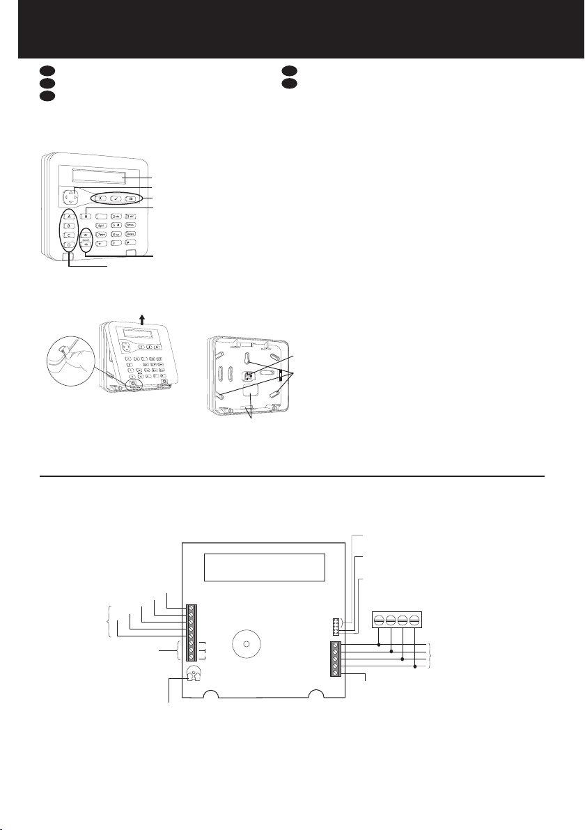
Étape2: montez la plaque arrière
1. Avec votre pouce (et non pas un outil),
rabattez les cache-vis et retirez les vis
(Figure 2).
2. Soulevez le couvercle pour le dégager de ses
charnières.
3. Montez la plaque arrière sur le mur (Figure 3).
Étape3: congurez les cavaliers
ADDR 2-4 − Si vous utilisez un modèle ancien
i-on16 ou i-on40*, chaque clavier doit avoir
une adresse séparée. Laissez tous les cavaliers
déconnectés pour l’adresse 1, ou montez le
cavalier approprié pour l’adresse 2, 3 ou 4. Pour
les autres centrales d’alarmes, laissez tous les
cavaliers ADDR déconnectés.
*Ne confondez pas l’i-on40 et le modèle i-on40H
moderne.
BRIGHT − Si vous utilisez un modèle ancien
i-on16 ou i-on40*, montez le cavalier de
façon à obtenir une luminosité totale du
rétroéclairage, ou retirez le cavalier pour une
luminosité normale. Pour les autres centrales
d’alarmes, laissez le cavalier déconnecté (la
luminosité peut être contrôlée à partir du menu
d’installation ou du menu local).
TERM − Montez le cavalier si le clavier se trouve
à une extrémité du bus. Le raccordement RS485
peut améliorer les performances dans des
environnements parasités de bruits électriques.
Étape4: raccordez tous les câbles
Raccordez tous les câbles à la carte électronique
(Figure 4). Les connexions du bus sont les

Page 5
seules connexions obligatoires vers le clavier.
Remarque:
•
avant de faire les raccordements, coupez
toute alimentation de la centrale d’alarme, y
compris la batterie.
•
En général, le clavier nécessite un câble
d’alarme 7/0.2 non blindé. Un câble blindé
peut être nécessaire si le site présente des
niveaux élevés d’interférence radio.
•
Maintenez le câble du clavier séparé
de tout autre câblage tel que les câbles
d’alimentation secteur, les câbles
téléphoniques, les câbles de réseau
informatique, les câbles RF et les câbles
d’alimentation des haut-parleurs ou des haut-
parleurs d’extension.
•
Pour plus de détails sur les besoins de
câblage, veuillez consulter le manuel
d’installation de la centrale d’alarme.
Lecteur de proximité externe
Veuillez vous reporter aux instructions
du KEY-EP pour les détails d’installation
d’un KEY-EP. Activez également la fonction
d’autoprotection EPTamper (voir la section
Utilisation du menu local).
Sortie
La polarité par défaut de la borne OP est 0
V lorsqu’elle est active et 12 Vcc lorsqu’elle
est inactive. Vous pouvez inverser la polarité
en utilisant l’option Sorties Filaires du menu
d’installation.
Zones
Pour utiliser les zones du clavier, vous devez
les activer en utilisant l’option Editer Clavier du
menu d’installation.
Les connexions de zone ZFS (zone filaire
supervisée), NF 4 fils et NF 2 fils sont prises
en charge.
Pour plus de détails sur la façon de câbler les
zones, veuillez consulter le manuel d’installation
de la centrale d’alarme.
Le numéro attribué à chaque zone par l’unité
de commande dépend du type de centrale
d’alarme que vous utilisez et si des extensions
ont déjà été configurées. Pour plus de détails
sur la numérotation des zones, veuillez
consulter le manuel d’installation de la centrale
d’alarme.
Étape5: mettez le cache avant en
place
Mettez le cache avant du clavier en place et
fixez-le à l’aide des deux vis.
Étape6: adressez et congurez le
clavier
Utilisez l’option Claviers Filaires du menu
d’installation pour:
•
Définir l’adresse. Sélectionnez Adresse BUS
Ext. dans le menu d’installation, puis appuyez
longuement sur A et simultanément. (Pour
les anciens panneaux, reportez-vous à la
section «Étape 3: configurez les cavaliers».)
Remarque: vous pouvez supprimer l’adresse
du clavier en appuyant simultanément sur D
et avec le boitier ouvert.
•
Sélectionnez les partitions (le cas échéant).
•
Configurez les touches A, B, C, D (facultatif).
Remarque: vous pouvez activer les LED
A, B, C, D en utilisant le menu local (voir
«Utilisation du menu local»).
•
Activez les zones du clavier et le lecteur de
proximité externe (le cas échéant).
•
Changez les paramètres tels que la luminosité
du rétroéclairage et le type de zone câblée (en
fonction des besoins).
Au besoin, vous pouvez régler le volume de la
tonalité ou régler les options locales, comme
décrit ci-dessous.
Réglage du volume de tonalité
Vous pouvez utiliser la commande de volume
illustrée à la Figure 4 pour régler le volume des
tonalités ne correspondant pas à des alarmes
(comme la tonalité d’entrée/sortie). Le volume
de tonalité des alarmes est prédéfini.
Avant d’ouvrir le clavier, accédez au menu
d’installation (pour éviter une alarme), puis
tournez la commande dans le sens horaire pour
augmenter le volume, ou dans le sens inverse
pour le réduire.
Utilisation du menu local
Le clavier est associé à un menu local, qui
propose des paramètres spécifiques au clavier
que vous utilisez. Pour accéder au menu:
1. Affichez le menu d’installation.
2. Enlevez le cache avant du clavier pour activer
l’interrupteur d’autoprotection.
3. Appuyez longuement sur B et pendant
deux secondes. Le texte suivant s’affiche.
MENU
ABCD LEDs x
4. Appuyez sur uou npour sélectionner
l’option souhaitée (n’appuyez pas sur ).
5. Appuyez sur ou pour modifier le réglage
(sur l’afficheur, une croix signifie désactivé et
une coche signifie activé).
6. Appuyez sur pour enregistrer les
changements ou sur pour les annuler.
Les options suivantes sont disponibles:
ABCD LEDs (LED ABCD)
Cette option permet d’activer ou de désactiver
les LED derrière les touches ABCD. Les LED
indiquent l’état d’armement du système (par
exemple, un armement partiel de A illumine la
LED derrière la touche A).
Backlight (Rétroéclairage)
Cette option permet d’activer ou de désactiver
le rétroéclairage local. L’activation du
rétroéclairage du clavier annule le réglage
de rétroéclairage du clavier défini dans le
menu d’installation et permet d’obtenir un
éclairage permanent du rétroéclairage avec une
luminosité normale.
La désactivation du rétroéclairage du clavier
permet de spécifier le mode de rétroéclairage
(allumé, éteint ou temporisé) et la luminosité
dans le menu d’installation.
Status OK LED (LED d’état OK)
Cette option concerne la LED «OK» verte située
derrière les touches de navigation. Lorsqu’elle
est activée, la LED s’allume en permanence
lorsqu’il n’y a pas d’anomalie non acquittée ou
de condition d’alarme présente.
Si vous désactivez la LED d’état OK, elle ne
s’allume pas quand le rétroéclairage du clavier
est éteint. Dès qu’une touche est appuyée
(ce qui allume le rétroéclairage), la LED verte
s’allume s’il n’y a pas d’anomalie ou d’alarme
non acquittée.
Cette option peut être utile si, par exemple, le
clavier est installé dans une chambre et s’il est
préférable qu’il reste éteint.
Status FLT LED (LED d’état FLT)
Cette option concerne la LED d’anomalie rouge
située derrière les touches de navigation.
Lorsqu’elle est activée, la LED s’allume en
permanence lorsqu’il y a une anomalie non
acquittée ou une condition d’alarme signalée
par la centrale d’alarme, comme une panne
se secteur ou une tentative de sabotage. La
LED rouge continue à s’allumer jusqu’à ce que
l’anomalie ou l’alarme soit éliminée.
Si vous désactivez la LED d’état FLT, la LED ne
s’allume pas quand le rétroéclairage du clavier
est éteint. Dès qu’une touche est appuyée (ce
qui allume le rétroéclairage), la LED rouge
s’allume s’il y a une anomalie ou une alarme
non acquittée.
Cette option peut être utile si, par exemple,
le clavier est installé dans une chambre et s’il
est préférable qu’il reste éteint (par exemple,
pour empêcher la LED de rester allumée en
permanence en attendant qu’un technicien
élimine l’alarme).
Remarque: cette option contrôle seulement la
LED rouge pour les anomalies et les alarmes
signalées au clavier par la centrale d’alarme.
Les anomalies suivantes sont détectées par le
clavier, et allument donc toujours la LED rouge,
quel que soit le réglage de la LED d’état FLT:
•
Pas d’adresse (systèmes extensibles
seulement) — LED d’anomalie rouge ou
clignotement lent.
•
Problèmes de communications — LED
d’anomalie rouge ou clignotement lent.
EP Tamper (KEY-KP01/KEY-KPZ01)
(Autoprotection EP)
Activez cette option si un lecteur de proximité
externe KEY-EP est connecté. Quand elle
est activée, le clavier interroge le KEY-EP à
intervalles réguliers et signale un événement de
sabotage si le KEY-EP ne répond pas.
Entretien
Pour l’entretien du clavier, il suffit de le nettoyer
et d’effectuer un test annuel à l’aide du menu
Test de la centrale d’alarme.
Nettoyez l’extérieur du boîtier à l’aide d’un
chiffon doux et sec. N’utilisez pas d’eau, de
solvants, ni tout autre produit de nettoyage du
commerce.
Caractéristiques
Tension d’alimentation: 12 Vcc.
Consommation de courant (max):
•
KEY-K01: 58 mA en alarme avec le
rétroéclairage activé. 18 mA au repos avec le
rétroéclairage éteint.
•
KEY-KP01: 60 mA avec lecteur de proximité
interne activé et le rétroéclairage allumé (pas
de lecteur de proximité externe). 25 mA au
repos avec le rétroéclairage éteint.
•
KEY-KPZ01: 65 mA avec lecteur de proximité
interne activé et le rétroéclairage allumé (pas
de lecteur de proximité externe). 27 mA au
repos avec le rétroéclairage éteint.
Sortie (KEY-KPZ01): collecteur ouvert, 12 Vcc
si inactif, 0 V si actif, 500 mA max, protégé par
fusible.
Fréquence du badge: 125 KHz
Dimensions: 127 x 127 x 25 mm (h,l,p).
Poids: 220 g
Température de fonctionnement: -10 à +55°C
Humidité relative maximale: 95%, sans
condensation
Matériau du boîtier: ABS
Normes de détection des intrusions: EN50131-
3:2009 Grade 3. PD6662:2017.
Environnement : classe II.
Protection: IP40, IK06.
Conformité EU: R&TTE: 1999/5/CE, CEM:
2004/108/CE, RoHS: 2011/65/CE, WEEE: 2012/19/
CE, EUP: 2005/32/CE, Basse tension: 2006/95/
CE, Sécurité générale: 2001/95/CE.
Certification NF et A2P
Remarque: La certification est pour le
KEY-KPZFR seulement.
Node composant répertorié NF et A2P avec
centrale i-on30RFR, i-on40HFR ou i-on200FR
Référentiel de certification NF 324-H58 (NF
et A2P).
AFNOR CERTIFICATION: www.marque-nf.com
Centre National de Prévention et de
Protection (CNPP Cert.): www.cnpp.com
COOPER Sécurité S.A.S:
www.cooperfrance.com
L’ensemble des informations, recommandations,
descriptions et consignes de sécurité formulées dans le
présent document reposent sur l’expérience et le jugement
d’Eaton Corporation (« Eaton ») et peuvent ne pas couvrir

Page 6
toutes les éventualités. Pour obtenir de plus amples
informations, contactez votre agence commerciale Eaton.
La vente du produit faisant l’objet du présent document
est soumise aux Conditions générales précisées dans les
politiques de vente d’Eaton applicables ou dans tout autre
accord contractuel établi entre Eaton et l’acquéreur.
IL N’EXISTE AUCUN ACCORD, AUCUNE ENTENTE
OU AUCUNE GARANTIE, EXPRESSE OU IMPLICITE,
NOTAMMENT AUCUNE GARANTIE D’ADÉQUATION
À UN USAGE PARTICULIER OU DE BONNE QUALITÉ
MARCHANDE, AUTRE QUE CEUX OU CELLES
EXPRESSÉMENT ÉNONCÉS DANS LES ÉVENTUELS
CONTRATS CONCLUS ENTRE LES PARTIES. L’INTÉGRALITÉ
DES OBLIGATIONS D’EATON SONT STIPULÉES DANS
CES CONTRATS. LE CONTENU DU PRÉSENT DOCUMENT
NE FAIT EN AUCUN CAS PARTIE, NI NE MODIFIE LES
ÉVENTUELS CONTRATS CONCLUS ENTRE LES PARTIES.
Eaton décline toute responsabilité contractuelle, délictuelle
(négligence y compris), stricte ou autre envers l’acquéreur
ou l’utilisateur quant à d’éventuels dommages ou pertes
particuliers, indirects, accessoires ou consécutifs de
quelque sorte que ce soit, y compris mais sans s’y limiter,
quant à tout dommage ou toute perte d’utilisation d’un
équipement, d’une installation ou d’un système électrique,
tout coût de capital, toute perte de puissance, toute dépense
supplémentaire liée à l’utilisation d’installations électriques
existantes, ou toute réclamation à l’encontre de l’acquéreur
ou de l’utilisateur par ses clients résultant de l’utilisation
des informations, recommandations et descriptions fournies
dans le présent document. Les infor¬mations contenues
dans le présent manuel sont susceptibles d’être modifiées
sans préavis.
© 2020 Eaton
Eaton Cooper Sécurité SAS PEE - rue Beethoven, 63204
Riom France www.cooperfrance.com
Service après-vente (France)Tél. : +33 (0) 820 867867,
de 08h30 à 17 h00 du lundi au vendredi Email: sales@
cooperfrance.com
Eaton Industries Belgium bvba-sprl Industrialaan 1, 1702
Groot-Bijgaarden Belgium www.coopersafety.be T: +32
IT
Introduzione
KEY-K01, KEY-KP01 e KEY-KPZ01 sono tastierini
cablati utilizzabili con i sistemi di rilevamento
delle intrusioni i-on.
Caratteristiche:
•
Consente agli installatori di accedere al menu
dell’Installatore e agli utenti di impostare/
disinserire il sistema o accedere al menu
Utente.
•
Lettore di prossimità integrato e terminali per
un lettore di prossimità KEY-EP esterno (solo
KEY-KP01 e KEY-KPZ01).
•
Due zone e un’uscita programmabile (solo
KEY-KPZ01).
•
Display e tasti retroilluminati.
•
Tasto di navigazione per menu, con LED di
avviso integrati.
•
Tasti A, B, C, D configurabili per la
configurazione, il disinserimento o l’uso delle
uscite, con LED integrati per visualizzare lo
stato impostato.
•
Rilevazione di manomissioni coperchio e
pannello posteriore.
Passo 1: selezionare la posizione di
montaggio
•
Posizionare la tastiera in un luogo non visibile
a eventuali intrusi e all’interno dell’area
protetta dal sistema di rilevamento delle
intrusioni.
•
Selezionare una posizione e un’altezza
convenienti per l’utente.
•
Verificare che la lunghezza massima dei cavi
non sia stata superata (consultare il Manuale
di installazione dell’unità di controllo).
•
Assicurarsi che un KEY-KP01 o un KEY-KPZ01
si trovino ad almeno 1 metro di distanza da
un altro lettore di prossimità e che non siano
posizionati dietro una porta, un attaccapanni
o altra barriera.
Passo 2: montare la piastra
posteriore
1. Con il pollice (e non un attrezzo), sollevare
i coperchi delle viti e rimuovere le viti
(Figura 2).
2. Sollevare il coperchio verso l’alto,
disimpegnandolo dalle cerniere.
3. Fissare la piastra posteriore alla parete
(Figura 3).
Passo 3: Congurazione dei
collegamenti
ADDR 2-4 − se si utilizza un i-on16 o i-on40*
legacy, ciascuna tastiera deve avere un
indirizzo separato. Lasciare tutti i collegamenti
per l’indirizzo 1 disattivati o impostare il
collegamento appropriato per gli indirizzi 2, 3 o
4. Per le altre unità di controllo, lasciare tutti i
collegamenti ADDR disattivati.
*Non confondere l’i-on40 con il moderno
i-on40H.
BRIGHT − se si utilizza un i-on16 o i-on40*
legacy, utilizzare il collegamento per abilitare
la luminosità piena per la retroilluminazione o
rimuovere il collegamento per una luminosità
normale. Per le altre unità di controllo, lasciare
il collegamento disattivato (la luminosità
può essere controllata tramite il menu
dell’Installatore o il menu locale).
TERM − usare il collegamento se la tastiera si
trova a un’estremità del bus. La terminazione
RS485 può migliorare le prestazioni in ambienti
elettricamente rumorosi.
Passo 4: Collegamento del
cablaggio
Collegare tutti i cavi al PCB (Figura 4). I
collegamenti del bus sono gli unici collegamenti
alla tastiera obbligatori. Nota:
•
Prima di installare il cablaggio, scollegare
l’alimentazione elettrica dall’unità di controllo,
compresa la batteria.
•
In generale, la tastiera richiede un cavo
di allarme non schermato 7/0,2. Un cavo
schermato può essere necessario se il sito
presenta alti livelli di interferenze radio.
•
Tenere il cavo della tastiera separato da altri
cavi, come i cavi dell’alimentazione di rete,
cavi telefonici, cavi di rete di computer, cavi
R.F. e cavi per cicalini o altoparlanti.
•
Per ulteriori i dettagli sui requisiti del
cablaggio, consultare il Manuale di
installazione dell’unità di controllo.
Lettore di prossimità esterno
Per i dettagli sull’installazione del KEY-EP, fare
riferimento alle istruzioni per il KEY-EP. Abilitare
inoltre EPTamper (consultare “Uso del menu
locale”).
Uscita
La polarità predefinita per il terminale OP è 0
V quando attivo e 12 V CC quando è inattivo.
È possibile invertire la polarità utilizzando
l’opzione Uscite Filari nel menu dell’Installatore.
Zone
Per utilizzare le zone della tastiera, è necessario
abilitarle usando l’opzione di modifica
della tastiera (EditaTastiera) nel menu
dell’Installatore.
Sono supportati collegamenti di zona quali FSL
(Fully-Supervised Loop), CC a 4 fili e CC a 2 fili.
Per dettagli sul cablaggio delle zone, fare
riferimento al Manuale di installazione dell’unità
di controllo.
Il numero di zona che l’unità di controllo
assegna a ciascuna zona dipende dal tipo di
unità di controllo che si sta utilizzando e se gli
espansori sono già configurati. Per dettagli sulla
numerazione delle zone, consultare il Manuale
di installazione dell’unità di controllo.
Passo 5: Montaggio del coperchio
anteriore
Montare il coperchio anteriore della tastiera e
fissarlo con le due viti.
Passo 6: Impostazione degli
indirizzi e congurazione della
tastiera
Utilizzare l’opzioneTastiere Filari nel menu
dell’Installatore per:
•
Impostare l’indirizzo. Selezionare Indirizzo
Disp.Bus nel menu dell’Installatore, quindi
tenere premuti A e insieme. (Per i pannelli
legacy, vedere il “Passo 3: Configurazione dei
collegamenti”.)
Nota: è possibile eliminare l’indirizzo della
tastiera premendo D e insieme con il
coperchio aperto.
•
Selezionare le partizioni (se applicabile).
•
Configurare i tasti A, B, C, D (opzionale).
Nota: è possibile abilitare i LED A, B, C, D
utilizzando il menu locale (vedere “Uso del
menu locale”).
•
Abilitare le zone della tastiera e il lettore di
prossimità esterno (se applicabile).
•
Modificare le impostazioni come la luminosità
della retroilluminazione e il tipo di zona
cablata (secondo le necessità).
Facoltativamente, è anche possibile regolare il
volume dei toni o impostare le opzioni locali,
come descritto di seguito.
Regolazione del volume dei toni
È possibile utilizzare il controllo del volume
mostrato nella Figura 4 per regolare il volume
dei toni non di allarme (come il tono di entrata/
uscita). Il volume dei toni di allarme è fisso.
Prima di aprire la tastiera, accedere al menu
dell’Installatore (per evitare un allarme),
quindi ruotare la manopola in senso orario
per aumentare il volume o in senso antiorario
per ridurlo.
Uso del menu locale
La tastiera è dotata di un menu locale con
diverse impostazioni specifiche per la tastiera
che si sta utilizzando. Per accedere al menu:
1. Visualizzare il menu dell’Installatore.
2. Rimuovere il coperchio anteriore della tastiera
(se non è già stato rimosso) per attivare
l’interruttore antimanomissione.
3. Premere senza rilasciare B e per due
secondi. Verranno visualizzate le seguenti
informazioni.
MENU
ABCD LEDs x
4. Premere uo nper selezionare l’opzione
richiesta (non premere ).
5. Premere o per modificare l’impostazione
(sul display, una croce significa disabilitato e
un segno di spunta significa abilitato).
6. Premere per salvare le modifiche o per
annullare le modifiche.
Le seguenti opzioni sono disponibili:
ABCD LEDs
Questa opzione abilita o disabilita i LED dietro i
tasti ABCD. I LED visualizzano lo stato impostato
del sistema (per esempio, l’impostazione del set
parziale A illumina il LED dietro il tasto A).
Retroilluminazione
Questa opzione abilita o disabilita
l’impostazione della retroilluminazione
locale. L’abilitazione della retroilluminazione
sulla tastiera annulla l’impostazione della
retroilluminazione della tastiera nel menu
dell’Installatore e abilita l’illuminazione
permanente della retroilluminazione, alla
luminosità normale.
La disattivazione della retroilluminazione sulla
tastiera consente di specificare la modalità

Page 7
di retroilluminazione (attivata, disattivata
o temporizzata) e la luminosità tramite le
impostazioni nel menu dell’Installatore.
Status OK LED
Questa opzione è correlata al LED verde
“OK” ubicato dietro i tasti di navigazione. Se
questa opzione è abilitata, il LED si illumina
costantemente se non sono presenti guasti non
rettificati o condizioni di allarme.
Se si disabilita Status OK LED, il LED non
si illumina quando la retroilluminazione
della tastiera è spenta. Non appena un
tasto viene premuto (con attivazione della
retroilluminazione), il LED verde si illumina
se non sono presenti guasti non rettificati o
allarmi.
L’opzione può essere utile se, per esempio, la
tastiera è installata in una camera da letto e
l’utente desidera che la tastiera non si illumini.
Status FLT LED
Questa opzione è correlata al LED rosso di
errore, ubicato dietro i tasti di navigazione.
Se abilitato, il LED si illumina costantemente
in caso di guasto non rettificato o allarme
segnalato dalla centralina, come un’interruzione
della corrente elettrica o una manomissione.
Il LED rosso continua a rimanere acceso fino
a quando il guasto o l’allarme non vengono
eliminati.
Se si disabilita Status FLT LED, il LED non
si illumina quando la retroilluminazione
della tastiera è spenta. Non appena un
tasto viene premuto (con attivazione della
retroilluminazione), il LED rosso si illumina se
un guasto non rettificato o un allarme sono
presenti.
L’opzione può essere utile se, per esempio, la
tastiera è installata in una camera da letto e
l’utente desidera che la tastiera non si illumini
(per esempio, per evitare che il LED si accenda
continuamente fino a quando un tecnico non
elimina l’allarme).
Nota: questa opzione controlla il LED rosso
solo per guasti e allarmi che l’unità di controllo
ha segnalato alla tastiera. I seguenti guasti
vengono rilevati dalla tastiera e illuminano
sempre il LED rosso, indipendentemente
dall’impostazione di Status FLT LED:
•
Nessun indirizzo (solo sistemi espandibili)
− lampeggiamento lento del LED di errore
rosso.
•
Problema di comunicazione −
lampeggiamento rapido del LED di errore
rosso.
EP Tamper (KEY-KP01/KEY-KPZ01)
Abilitare questa opzione se un lettore di
prossimità esterno KEY-EP è collegato. Se
abilitata, la tastiera esegue il polling di KEY-EP
a intervalli regolari e segnala un evento di
manomissione se KEY-EP non risponde.
Manutenzione
L’unica manutenzione richiesta è la pulizia e un
test annuale della tastiera tramite il menuTest
dell’unità di controllo.
Pulire l’esterno dell’involucro con un panno
morbido e asciutto. Non utilizzare acqua,
solventi o detergenti proprietari.
Speciche tecniche
Tensione di alimentazione: 12 V CC.
Assorbimento elettrico (max):
•
KEY-K01: 58 mA in allarme con
retroilluminazione alta. 18 mA a riposo con
retroilluminazione spenta.
•
KEY-KP01: 60 mA con lettore di prossimità
interno acceso e retroilluminazione alta
(nessun lettore di prossimità esterno). 25 mA
a riposo con retroilluminazione spenta.
•
KEY-KPZ01: 65 mA con lettore di prossimità
interno acceso e retroilluminazione alta
(nessun lettore di prossimità esterno). 27 mA
a riposo con retroilluminazione spenta.
Uscita (KEY-KPZ01): Open collector, 12 V cc
inattivo, 0 V attivo, 500 mA max, protetto con
fusibile.
Frequenza tag di prossimità: 125 KHz.
Dimensioni: 127 x 127 x 25 mm (a,l,p).
Peso: 220 g.
Temp. di esercizio: da -10°C a +55°C.
Umidità relativa massima: 95%, senza
condensa.
Materiale involucro: ABS.
Standard intrusione: EN50131-3:2009 Grade 3.
PD6662:2017.
Ambiente: Classe II.
Grado di protezione: IP40, IK06.
Conformità UE: R&TTE: 1999/5/EC, EMC:
2004/108/EC, RoHS: 2011/65/EC, WEEE: 2012/19/
EC, EUP: 2005/32/EC, Bassa tensione: 2006/95/
CE, Sicurezza generale: 2001/95/CE.
Le informazioni, raccomandazioni, descrizioni e indicazioni
di sicurezza contenute nel presente documento sono basate
sull’esperienza e sul giudizio di Eaton Corporation (“Eaton”)
e potrebbero non coprire tutte le eventualità. Per ulteriori
informazioni, consultare l’ufficio vendite di Eaton. La vendita
del prodotto illustrato nel presente materiale informativo
è soggetta ai termini e alle condizioni definiti nelle relative
politiche di vendita di Eaton o in altri accordi contrattuali tra
Eaton e l’acquirente.
NON SUSSISTONO INTESE, ACCORDI O GARANZIE,
INCLUSE GARANZIE DI IDONEITÀ A UN DETERMINATO
SCOPO O DI COMMERCIABILITÀ, NÉ ESPRESSI NÉ
IMPLICITI, DIVERSI DA QUELLI SPECIFICATAMENTE
INDICATI NEI CONTRATTI ESISTENTI TRA LE PARTI. OGNI
CONTRATTO DI QUESTO TIPO COSTITUISCE L’INTERO
OBBLIGO DI EATON. I CONTENUTI DEL PRESENTE
DOCUMENTO NON COSTITUISCONO PARTE INTEGRANTE
NÉ MODIFICA DEI CONTRATTI ESISTENTITRA LE PARTI.
Eaton non sarà in alcun caso responsabile nei confronti
dell’acquirente o dell’utente in base a contratto, atto illecito
(negligenza compresa), responsabilità oggettiva o altro
per nessun tipo di danno o perdita speciale, indiretto,
incidentale o conseguente, tra cui, a titolo esemplificativo,
danni o perdite di utilizzo dell’attrezzatura, dell’impianto
o del sistema di alimentazione, spese di investimento,
perdite di energia, costi aggiuntivi per l’utilizzo degli
impianti energetici esistenti o rivendicazioni sollevate nei
confronti dell’acquirente o utente dai rispettivi clienti che
derivino dall’utilizzo delle informazioni, raccomandazioni
e descrizioni contenute nel presente documento. Le
informazioni contenute nel presente manuale sono soggette
a modifica senza preavviso.
© 2020 Eaton
Cooper CSA srl, Via San Bovio 3, 20090 Segrate (MI) Italia
Tel. +39 02959501 Fax. +39 0295950597
www.coopercsa.it
Email: [email protected]
NL
Inleiding
De KEY-K01, KEY-KP01 en KEY-KPZ01 zijn
bekabelde toetsenborden, geschikt voor i-on
inbraak detectie systemen.
Kenmerken:
•
Geeft installateurs toegang tot het
installatiemenu, laat gebruikers het systeem
in/uitschakelen of naar het gebruikersmenu
gaan.
•
Interne proximity lezer, en klemmen voor
een externe KEY-EP proximity lezer (alleen
KEY-KP01 en KEY-KPZ01).
•
Twee zones en een programmeerbare uitgang
(alleen KEY-KPZ01).
•
Scherm en toetsen met
achtergrondverlichting.
•
Navigatietoets voor menu’s, met ingebouwde
waarschuwings-LED’s.
•
Configureerbare A, B, C, D toetsen voor in- en
uitschakeling of uitgangen, met ingebouwde
LED’s om status te tonen.
•
Deksel en achterkant met sabotage-detectie.
Stap 1: Montageplaats kiezen
•
Plaats toetsenbord buiten het zicht van
mogelijke indringers en binnen het bewaakte
(middels bewegingsdetector) gebied van uw
inbraak detectie systeem
•
Kies een passende plaats en hoogte voor de
gebruikers.
•
Controleer dat de maximale kabellengten
niet worden overschreden (zie
installatiehandleiding van controlepaneel).
•
Plaats een KEY-KP01 of KEY-KPZ01 nooit
dichter dan 1 meter bij andere proximity
lezers en niet achter een deur, kapstok of
andere obstakels.
Stap 2: Grondplaat monteren
1. Wip de kapjes met uw duim (geen
gereedschap) omhoog, zodat u de schroeven
ziet waarmee het bedieningspaneel aan de
grondplaat vastzit (afb. 2).
2. Draai de twee schroeven los en til het deksel
omhoog uit zijn scharnieren.
3. Monteer de grondplaat tegen de wand
(afb. 3).
Stap 3: Congureer de verbindingen
ADRES 2-4 − Als u een oudere i-on16 of i-on40*
gebruikt, moet elk toetsenbord een apart adres
hebben. Laat alle verbindingen eruit voor adres
1, of plaats de juiste verbinding voor adres 2,
3 of 4. Bij andere controlepanelen laat u alle
adresverbindingen weg.
*Verwar de i-on40 niet met de moderne i-on40H.
HELDER − Als u een oudere i-on16 of i-on40*
gebruikt, plaatst u de verbinding om een zo
helder mogelijke achtergrondverlichting te
krijgen, of u verwijdert de verbinding voor de
normale helderheid. Bij andere controlepanelen
laat u de verbinding weg (helderheid regelbaar
via installatiemenu of lokaal menu).
AFSLUITING − Plaats de verbinding als het
toetsenbord aan het ene uiteinde van de bus
zit. RS485-afsluiting kan prestaties verbeteren in
omgevingen met veel elektrische stoorsignalen.
Stap 4: Sluit de hele bedrading aan
Sluit alle draden aan op de printplaat (afb. 4).
De busaansluitingen zijn de enige verplichte
aansluitingen op het toetsenbord. Opmerking:
•
Voordat u enige bedrading aanbrengt, moet
u de hele voeding van het controlepaneel
afkoppelen, inclusief de batterij.
•
Het toetsenbord heeft doorgaans een 7/0,2
niet-afgeschermde alarmkabel nodig. Een
afgeschermde kabel is eventueel nodig op
punten met sterke stoorsignalen.
•
Houd de toetsenbordkabel gescheiden van
enige andere bedrading, zoals 220V leidingen,
telefoondraden, computer-netwerkkabels,
coaxkabels en voedingskabels voor sirenes
en luidsprekers op afstand.
•
De volledige bedradingsvoorschriften
vindt u in de installatiehandleiding van het
controlepaneel.
Externe proximity lezer
Raadpleeg de KEY-EP instructies en lees hoe u
een KEY-EP installeert. Activeer ook EP Sabotage
(zie Lokaal menu gebruiken).
Uitgang
De standaard polariteit van de OP-klem is 0V
indien actief en 12Vdc indien inactief. U kunt de
polariteit omkeren via de optie Bekab uitgangn
in het installatiemenu.
Zones
Om de toetsenbordzones te gebruiken, moet u
ze activeren via de optie Bedpan wyzigen in het
installatiemenu.
Volledig bewaakte kring (FSL), 4-draads CC
en 2-draads CC zone-aansluitingen worden
ondersteund.
Als u meer over de bedrading van de zones wilt
weten, raadpleegt u de installatiehandleiding
van het controlepaneel.
Het zone-nummer van het controlepaneel,
toegekend aan elke zone, hangt af van het
gebruikte type controlepaneel en of de
expanders al zijn geconfigureerd. Meer

Page 8
informatie over de zone-nummering vindt u in
de installatiehandleiding van het controlepaneel.
Stap 5: Bevestig het voordeksel
Zet het voordeksel van het controlepaneel met
de twee schroeven vast.
Stap 6: Adresseer en congureer
het toetsenbord
Gebruik de optie Bekab bed pan in het
installatiemenu om:
•
Het adres in te stellen. Kies Adres busapp.
in het installatiemenu en houd A en
gelijktijdig ingedrukt (bij oudere panelen, zie
“Stap 3: Configureer de verbindingen”).
Opmerking: U kunt het adres van het
toetsenbord wissen door D en tegelijk
ingedrukt te houden terwijl het deksel
geopend is.
•
Kies de partities (indien van toepassing).
•
Configureer de toetsen A, B, C en D
(optioneel).
Opmerking: U kunt de LED’s A, B, C en D
activeren via het lokale menu (zie “Lokaal
menu gebruiken”).
•
Activeer de toetsenbordzones en de externe
proximity lezer (indien van toepassing).
•
Verander de instellingen, zoals helderheid
achtergrondverlichting en type bekabelde
zone (zo nodig).
U kunt desgewenst ook het geluidsvolume
veranderen of lokale opties instellen, zoals
hieronder beschreven.
Geluidsvolume veranderen
U kunt de volumeregeling uit afb. 4 gebruiken
om het volume van niet-alarmsignalen te
veranderen (zoals geluidssignaal bij inloop/
uitloop). Het volume van de alarmsignalen
staat vast.
Voordat u het toetsenbord opent, gaat u naar
het installatiemenu (zodat het alarm niet
afgaat), daarna draait u de knop rechtsom om
het volume te verhogen of linksom om het te
verlagen.
Lokaal menu gebruiken
Het toetsenbord heeft een lokaal menu met een
aantal instellingen, die specifiek zijn voor het
gebruikte toetsenbord. Zo opent u het menu:
1. Open het installatiemenu.
2. Verwijder het voordeksel van het toetsenbord
(indien nog niet verwijderd) om de
sabotageschakelaar te activeren.
3. Houd B en twee seconden tegelijk
ingedrukt. Nu ziet u het volgende.
MENU
ABCD LEDs x
4. Druk op uof nom de gewenste optie te
kiezen (druk niet op ).
5. Druk op of om de instellingen te
veranderen (een kruis op het scherm
betekent gedeactiveerd, een vinkje betekent
geactiveerd).
6. Druk op om de veranderingen te bewaren
of op om ze te annuleren.
De volgende opties zijn beschikbaar:
LED’s ABCD
Via deze optie activeert of deactiveert u de LED’s
achter de toetsen ABCD. De LED’s tonen de
instelstatus van het systeem (als u bijv. gedeelte
A instelt, brandt de LED achter toets A).
Achtergrondverlichting
Via deze optie activeert of deactiveert u de
lokale instelling van de achtergrondverlichting.
Als u de achtergrondverlichting op het
toetsenbord activeert, dan wordt de
dezelfde instelling in het installatiemenu
onderdrukt, wat resulteert in een permanente
achtergrondverlichting met normale helderheid.
Als u de achtergrondverlichting op
het toetsenbord deactiveert, kunt u de
achtergrondverlichtingsmodus (aan, uit,
timer) en de helderheid in het installatiemenu
instellen.
Status OK-LED
Deze optie gaat over de groene OK-LED achter
de navigatietoetsen. Na activering zal de LED
continu branden als er geen onopgeloste fout of
alarmtoestand aanwezig is.
Als u de Status OK-LED deactiveert, brandt de
LED niet als de achtergrondverlichting van het
toetsenbord uitstaat. Zodra u een toets indrukt
(die de achtergrondverlichting inschakelt), licht
de groene LED op als er geen onopgeloste fout
of alarmtoestand is.
Deze optie kan bijvoorbeeld nuttig zijn als het
toetsenbord in een slaapkamer is gemonteerd
en de gebruiker wenst dat het onverlicht blijft.
Status FLT-LED
Deze optie gaat over het rode fout-LED achter
de navigatietoetsen. Na activering zal de LED
continu branden als er een onopgeloste fout of
alarmtoestand is, die het controlepaneel heeft
gemeld, zoals een stroomuitval of sabotage.
De rode LED blijft aan totdat de fout of
alarmtoestand is opgelost.
Als u de Status FLT-LED, deactiveert, brandt de
LED niet als de achtergrondverlichting van het
toetsenbord uitstaat. Zodra u een toets indrukt
(die de achtgrondverlichting inschakelt), licht
de rode LED op als er een onopgeloste fout of
alarmtoestand is.
Deze optie kan bijvoorbeeld nuttig zijn als het
toetsenbord in een slaapkamer is gemonteerd
en de gebruiker wenst dat het onverlicht blijft
(bijv. om te verhinderen dat de LED continu
aanblijft totdat een monteur komt om het alarm
op te heffen).
Opmerking: Via deze optie stelt u de rode
LED alleen in voor fouten en alarmen die
het controlepaneel aan het toetsenbord
heeft gemeld. De volgende fouten worden
gedetecteerd door het toetsenbord en daardoor
zullen ze de rode LED altijd laten branden,
ongeacht de instelling van de Status FLT-LED:
•
Geen adres (alleen uitbreidbare systemen) —
rode fout-LED knippert langzaam.
•
Communicatieprobleem — rode fout-LED
knippert snel.
EP Sabotage (KEY-KP01/KEY-KPZ01)
Activeer deze optie als een KEY-EP externe
proximity lezer is aangesloten. Na activering zal
het toetsenbord de KEY-EP periodiek afvragen
en een sabotage melden als de KEY-EP niet
reageert.
Onderhoud
Het enige vereiste onderhoud is de reiniging
en jaarlijkse test van het toetsenbord via het
testmenu op het controlepaneel.
Reinig de buitenkant van de behuizing
met een zachte droge doek. Gebruik geen
water, oplosmiddelen of huishoudelijke
schoonmaakmiddelen.
Specicaties
Voedingsspanning: 12Vdc.
Stroomverbruik (max.):
•
KEY-K01: 58mA in alarm met heldere
achtergrondverlichting. 18mA ruststroom met
achtergrondverlichting uit.
•
KEY-KP01: 60mA met interne proximity lezer
aan en heldere achtergrondverlichting (geen
externe proximity lezer). 25mA ruststroom
met achtergrondverlichting uit.
•
KEY-KPZ01: 65mA met interne proximity lezer
aan en heldere achtergrondverlichting (geen
externe proximity lezer). 27mA ruststroom
met achtergrondverlichting uit.
Uitgang (KEY-KPZ01): Open collector, 12Vdc
inactief, 0V actief, 500mA max, beveiligd met
zekering.
Frequentie toegangslabel: 125KHz.
Afmetingen: 127 x 127 x 25mm (h,b,d).
Gewicht: 220g.
Gebruikstemperatuur: -10 °C tot +55 °C.
Max. relatieve vochtigheid: 95%,
niet-condenserend.
Materiaal behuizing: ABS.
Inbraaknormen: EN50131-3:2009 Grade 3.
PD6662:2017.
Milieu: Klasse II.
Bescherming: IP40, IK06.
EU-conformiteit: R&TTE: 1999/5/EC, EMC:
2004/108/EC, RoHS: 2011/65/EC, WEEE: 2012/19/
EC, EUP: 2005/32/EC, Laagspanning: 2006/95/EC,
Algemene veiligheid: 2001/95/EC.
De informatie, aanbevelingen, beschrijvingen en
veiligheidsaanbevelingen in dit document zijn gebaseerd
op de ervaring en de beoordeling van Eaton Corporation
(‘Eaton’) en dekken niet alle eventualiteiten. Indien u
meer informatie nodig heeft, raadpleegt u een Eaton-
verkoopkantoor. De verkoop van het in dit document
getoonde product valt onder de algemene voorwaarden
zoals die zijn beschreven in het betreffende Eaton-
verkoopbeleid en andere contractuele overeenkomsten
tussen Eaton en de koper.
ER GELDEN GEEN ANDERE EXPLICIETE OF IMPLICIETE
AFSPRAKEN, OVEREENKOMSTEN, GARANTIES
WAARONDER GARANTIES M.B.T. DE GESCHIKTHEID
VOOR EEN BEPAALD DOEL OF VERKOOPBAARHEID DAN
DIE UITDRUKKELIJK GENOEMD ZIJN IN EEN BESTAAND
CONTRACTTUSSEN DE PARTIJEN. EEN DERGELIJK
CONTRACT BEVAT ALLE VERPLICHTINGEN VAN EATON.
DE INHOUD VAN DIT DOCUMENT MAAKT GEEN DEEL UIT
VAN HET CONTRACT TUSSEN PARTIJEN EN WIJZIGT HET
CONTRACT NIET.
Eaton is in geen geval verantwoordelijk jegens de koper of
de gebruiker op grond van het contract, een onrechtmatige
daad (inclusief nalatigheid), strikte aansprakelijkheid of
anderszins voor enige bijzondere, indirecte, incidentele
of gevolgschade of verlies, inclusief maar niet beperkt tot
beschadiging of verlies van het gebruik van apparatuur,
centrale of elektriciteitssysteem, kapitaalkosten,
stroomverlies, extra uitgaven bij het gebruik van bestaande
stroomfaciliteiten of claims jegens de koper of gebruiker
door zijn klanten die voortvloeien uit het gebruik van
informatie, aanbevelingen en beschrijvingen in dit
document. De informatie in deze handleiding kan worden
gewijzigd zonder enige aankondiging vooraf.
© 2020 Eaton
Eaton, Security House, Vantage Point Business Village,
Mitcheldean, GL17 0SZ.
www.touchpoint-online.com
Product Support (UK)Tel: +44 (0) 1594 541978 available
09:30 to 18:00 Monday to Friday.
email: securitytechsuppor[email protected]
Part number 13404129 Issue 3
06/01/20
This manual suits for next models
2
Table of contents
Other Scantronic Keypad manuals