User guide OC 2010 (UK 07/2011 CE) page 6 of 16
2.0. Installation
2.1. Control at delivery
Afterunpacking,pleaseconrmthatthedelivereditemsareinaccordancewiththepackinglist.
Possible inconsistencies should be reported to the supplier immediately. If some parts are dam-
aged please contact the shipping company.
2.2. Instrument identication
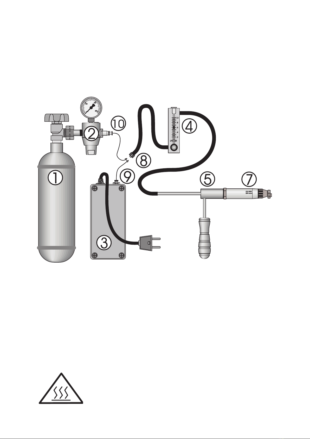
The oxygen control system OC 2010-LSU, as standard, consists of a measuring probe OS 2014,
andsignalamplierOC2010-LSU,aguidetubeincludingagasketand4mountingscrewsare
optional.
Measuring probe
The measuring probe contains a measuring cell,
a heating element and a connection cable with
a multipole connector.
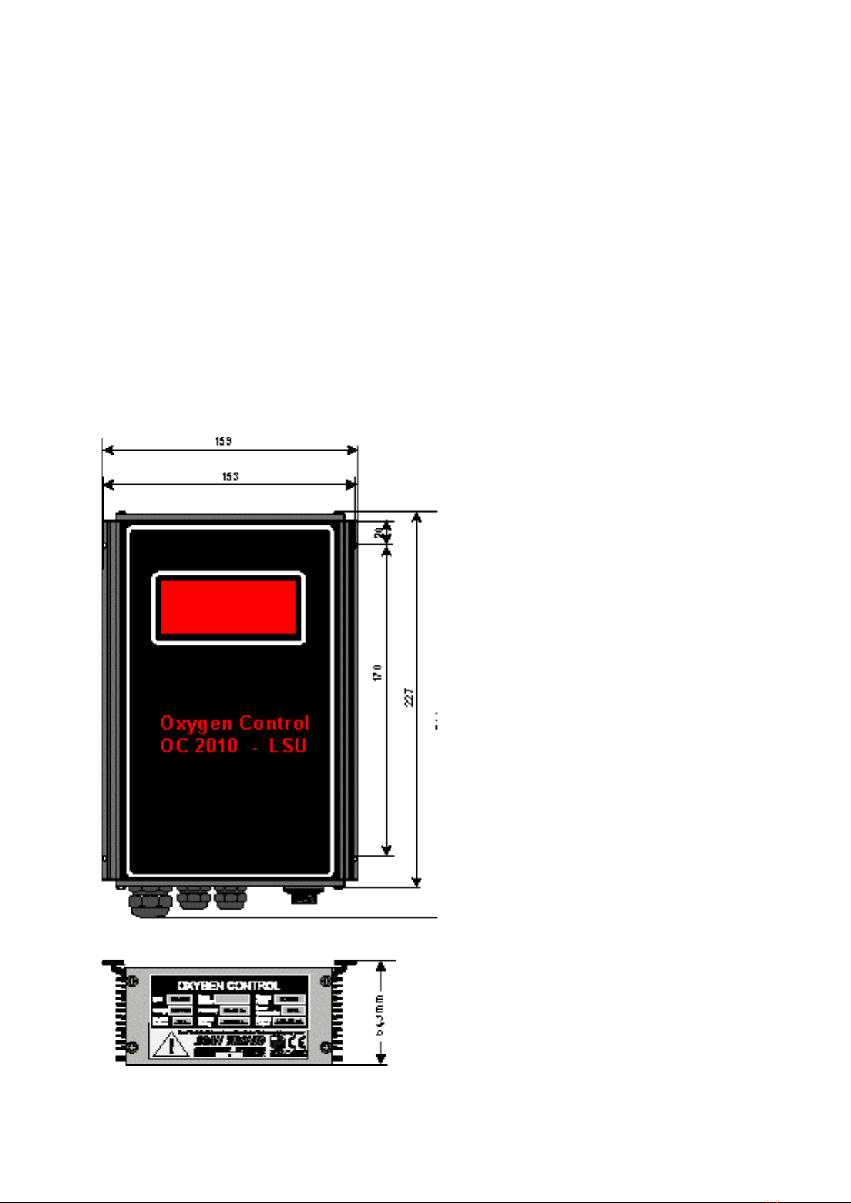
Signal amplier
Themeasuringamplierisbuiltintoanalu-
minium cabinet, and contains a power-supply,
ameasuringamplier,alinearizationunit,an
alarm circuit and a current loop output circuit.
2.3. Place of installation
Satisfactory operation, faultless function and
minimal maintenance is achieved by paying
attention to the following notes:
1)The tting place for the probe should
be chosen in a way that protects the probe
againstmechanical damage.Theuegas-
temperature has to lie within the given
limits of the probe at the measuring point.
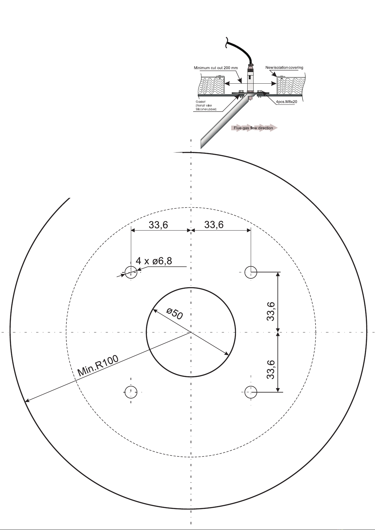
2) The gas, which passes the probe, must
be representative.At large crosssections it is
recommended to use the guide-tube (which
leads the gas to the probe).
3)The ue-gas channel must be controlled
forholesandleakages.Oozingofsurroun-
ding air into the channel, before and
after the probe, inuences the accuracy
af to the oxygen measurement in an
unwanted direction.
4) The zirkoniumdioxide measuring cell re-
acts on changes in the concentration
of oxygen (e.g. the partial pressure of the
oxygen), and on changes in the negative
pressure at the measuring point.
To keep this effect at a minimum, the
probe must not be installed between id-
fans and their regulation valves or in the
immedate vicinity of these. The pressure
difference must be kept under 100 mm
water column (H2O).
5) The installation place of the signal
ampliermustbechosensothattheambient
temperature at any time lies over 0 o C,
and below 60 o C.
6) The distance between measuring probe
andsignalampliercannotexceed2,0m.
7) At high gas-temperatures a special guide
tube to be welded into the ue channel
wall can be delivered.
Attention
Mounting of the probe itself should not take
place before the completion of all pipe- and
ue-worksattheboiler,andtheburnerisready
to start.
Care should be taken to assure that the system
is constantly powered and the probe is heated
also when the boiler is out of service.