manuals.online logo
Brands
  1. Home
  2. •
  3. Brands
  4. •
  5. Schacht
  6. •
  7. Other
  8. •
  9. Schacht MIGHTY WOLF LOOM Series User manual

Schacht MIGHTY WOLF LOOM Series User manual

MIGHTY WOLF LOOMTM
Assembly InstructIons
Find out more at schachtspindle.com
Schacht Spindle Company 6101 Ben Place Boulder, CO 80301
p. 303.442.3212 f. 303.447.9273
© 2018 Schacht Spindle Company, Inc. 12.18
4. Continue holding onto the front and
rear beams and allow the loom to unfold
all the way. If there is a warp on the loom,
you may need to hold down the brake
release pedal with your foot to loosen the
warp as you unfold the loom.
UNFOLDING THE LOOM
1. Remove all plastic wrap from the loom.
Remove both shipping braces by slightly
loosening the back beam knobs and
front beam screws holding them in place.
Discard the braces and tighten the knobs
and screws.
2. Slightly loosen the black fold knobs
on each side of the loom (Figure 1).
Generally, a single turn will do.
Loosening the knobs all the way or
removing them can cause the loom to
collapse, which could result in injury.
3. Stand at the side of the loom. Hold the
front and rear beams together slightly. Pull
the slide lock bars out toward the back of
the loom.
BEFORE YOU BEGIN
■All Wolf looms assemble in a similar way. Watch the Baby Wolf assembly video on our
Youtube channel (www.youtube.com/user/schachtspindle).
■You’ll nd a complete labelled diagram of the Wolf loom in your Maintenance and
Warranty manual and at schachtspindle.com.
■Wolf loom legs are called out by where they cross each other. The legs that touch the
ground at the front of the loom are called “inside” legs because they are covered by the
“outside” legs when they cross at the loom center.
■The beater is at the front of the loom. The brake is on the right side of loom.
FIGURE 1: UNFOLDING THE LOOM
slot in
castle
FRONT OF
LOOM
slide lock bar
shipping brace
front beam
screw
fold knob
back beam
knob
FL3002
FL3004
FL3012
FL3014
FL3022
FL3024
1X 3/8" cap nut for warp beam crank
handle
1X 3/8" washer for warp beam crank
handle
3X extra 8/32" hex nuts for shafts
Maintenance and Warranty Manual
4-shaft looms:
800X heddles
24X tie-up cords
8-shaft and 4 Now-4 Later looms:
1000X heddles
80X tie-up cords
PARTS
Wrapped onto warp beam:
3X apron bars
2X lease sticks (with holes)
2X additional 37" dowels (cherry looms
only)
Accessory pack:
1X brass reed hook
1X warp beam crank handle
14X 29" apron cords (or 2X 30-foot apron
cords for cherry looms only)
– 2 –
ATTACHING THE APRON BARS
For cherry Wolf looms, see the special
instructions for attaching the apron bars.
There is one cord for each hole in the
cloth and warp beams. Insert one end of a
cord through a hole in the beam and pull
the cord through. Then insert the other
end through the second hole in the end
of the cord that you just put through the
beam. Pull rmly on the cord to tighten
(Figure 3A). Repeat across the cloth beam
and the warp beam.
To attach the apron bar to the apron
cords, take a pinch of the cord about
4" from the end (Figure 3B). Insert the
5. When the loom has completely
opened, push the fold knobs down to the
bottom of the slots in the castle. Tighten
the knobs. You can push in the slide lock
bars to get them out of the way.
FOLDING THE LOOM
6. To prevent treadles from dragging on
the oor when the loom is folded, attach
every treadle to at least one tie-up cord.
7. Start folding the loom: Loosen the fold
knobs one full turn and pull them up in
their slots.
8. With one hand on the rear beam and
one hand on the front beam, push the
loom together as far as it will go.
9. Tighten the fold knobs. Push the slide
lock bars in towards the front of the loom.
ATTACHING THE WARP BEAM
CRANK HANDLE
The warp beam crank handle attaches
to a threaded rod on the inside right leg
(Figure 2). Locate the washer, cap nut,
and the warp beam crank handle in the
accessory pack. Place the 3/8" washer and
then the metal handle on the rod, with the
wooden handle facing out. Secure with the
the 3/8" cap nut.
When you’re weaving, the crank should
be pushed off of the cap nut. To engage
the crank for turning the warp beam, pull
the hexagonal hole in the crank onto the
cap nut.
FIGURE 2: WARP BEAM CRANK HANDLE
FIGURE 3: INSTALLING APRON CORDS
A B DC loop
Visit youtube.com/user/schachtspindle for an apron cord installation video.
3/8"
washer
cap nut
threaded rod
wooden
handle
metal
handle
– 3 –
one of the slots in the shaft frame. Using
very gentle pressure, ex the heddle
bar just enough to t the other end into
the slot on the opposing side of the shaft
frame. Push approximately half of the
heddles to each end of the shaft.
Put the shaft back in the loom and secure
the jack pin with the hex nut. Repeat
for the other shafts. Be sure to keep the
heddles oriented in the same direction for
easier threading.
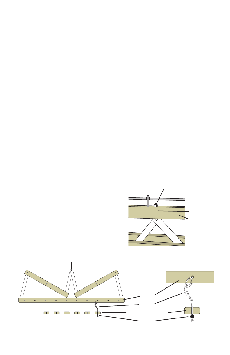
INSTALLING THE TIE-UP CORDS
There is one tie-up cord for every lamm
hole: 24 for 4-shaft looms; 80 for 8-shaft
and 4 Now-4 Later looms. Loop one end
of each tie-up cord through a hole in the
lamm.
Loop one end of each tie-up cord through
a hole in the lamm. Tie shafts to a treadle
by slipping a tie-up cord into the slot in a
treadle (Figure 5). Work from the front
lamm to the rear lamm for each treadle.
pinched cord through the second hole in
the cord. Pull on the pinched cord until
a new loop forms that is large enough
for the apron bar to slip through (Figure
3C). Slide the apron bar through the loop
(Figure 3D) and pull tight. Repeat until all
cords are attached to the apron bar. Attach
the other apron bar to its beam in the
same way.
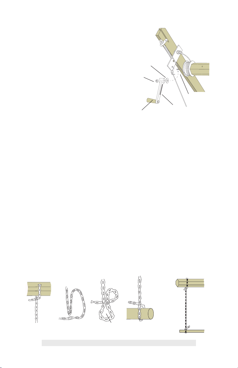
USING THE BEATER PIN
The small metal pin attached to the inside
right leg holds the beater upright during
warping. Push the pin through the hole
in the leg and then through the slot in the
beater side. Pull out the beater pin and
replace it in its holder before weaving or
before folding the loom.
INSTALLING THE HEDDLES
There are 800 heddles for 4-shaft looms
and 1000 for 8-shaft and 4 Now-4 Later
looms.
Remove the shafts from the loom
by removing the rubber rings and
unscrewing the small hex nuts from the
jack pins (Figure 4). Pull the shaft straight
up and out of the loom. When you put the
shaft back in the loom, be sure to insert
the jack pin back into the hole and secure
it with the hex nut. Replacing the rubber
ring is optional.
Lay the shaft on a at surface. Lay two
heddle bars next to the heddles. Carefully
slide a group of heddles onto the heddle
bars. Fit one end of each heddle bar into
FIGURE 5: INSTALLING TIE-UP CORDS
FIGURE 4: JACK PIN ATTACHMENT
shaft
frame
hex nut
jack pin
lamm
tie-up
end of treadle (rear)
button
– 4 –
After you have completed your tie-up,
check each treadle by pushing it all the
way to the oor and releasing it, making
sure that the button of each tie-up cord is
up against the treadle and that each cord
hangs straight down to the treadle.
There is a 1/2" round depression on the
underside of each treadle end to prevent
the tie-ups from slipping off when the
loom is folded.
ADJUSTING THE FRICTION BRAKE
The friction brake can be adjusted by
tightening or loosening the eye bolt. This
will increase or decrease the tension on
the spring, which will in turn increase or
decrease the tension on the brake bar and
the brake cable.
Always press down on the brake pedal
while you are winding on the warp or
advancing the warp on the cloth beam.
REMOVING THE BACK BEAM
The back beam can be removed for better
access to the heddles when you thread
the loom. Loosen the back beam knobs
on each side of the back beam and lift
the beam out (Figure 7). To replace the
back beam, slide it back into the legs and
tighten the knobs.
When moving the loom, be sure to lift it
using the cloth and warp beams, not the
front and back beams.
ADJUSTING THE BEATER
The height of your beater has been set at
the factory to accommodate most weaving
situations. If you want to raise or lower the
beater, loosen the two nuts on the inside of
each of the metal beater supports. Position
the beater at the desired height and
tighten the nuts. Be sure that you have set
both beater sides at the same height. •
FIGURE 7: REMOVING BACK BEAM
back beam knob
FIGURE 6: FRICTION BRAKE ADJUSTMENT
eye
bolt
spring

This manual suits for next models

12

Other Schacht Other manuals

Schacht FL3051 User manual

Schacht

Schacht FL3051 User manual

Schacht WOLF FL3051 User manual

Schacht

Schacht WOLF FL3051 User manual

Schacht WOLF PUP 8.10 User manual

Schacht

Schacht WOLF PUP 8.10 User manual

Popular Other manuals by other brands

Maxspect Jump owner's manual

Maxspect

Maxspect Jump owner's manual

Nedap COMBI-BOOSTER installation guide

Nedap

Nedap COMBI-BOOSTER installation guide

DANA Spicer Drive Axles Service manual

DANA

DANA Spicer Drive Axles Service manual

Xiaomi Mi VR Helmet manual

Xiaomi

Xiaomi Mi VR Helmet manual

Whirlpool 8535841 installation instructions

Whirlpool

Whirlpool 8535841 installation instructions

Siemens OpenAir ASK791.165 installation instructions

Siemens

Siemens OpenAir ASK791.165 installation instructions

IBM HS21 BLADECENTER - FOR SPECWEB2005 specification

IBM

IBM HS21 BLADECENTER - FOR SPECWEB2005 specification

Rupes KR2 quick start guide

Rupes

Rupes KR2 quick start guide

impey Radiate Shower Tray installation guide

impey

impey Radiate Shower Tray installation guide

Eureka 4880 Series owner's guide

Eureka

Eureka 4880 Series owner's guide

Fossil FUEL DIGITAL manual

Fossil

Fossil FUEL DIGITAL manual

Nordson NT-T10 operating manual

Nordson

Nordson NT-T10 operating manual

Water Claw Flash Xtractor II AC002 manual

Water Claw

Water Claw Flash Xtractor II AC002 manual

Master Halco PostMaster Installation guidelines

Master Halco

Master Halco PostMaster Installation guidelines

SNOWJOE 320E-PRO Operator's manual

SNOWJOE

SNOWJOE 320E-PRO Operator's manual

RiDD RDD SKATE95 SERIES manual

RiDD

RiDD RDD SKATE95 SERIES manual

Delta Electronics MA0505-SAOIN-A0 Specifications

Delta Electronics

Delta Electronics MA0505-SAOIN-A0 Specifications

Oase Vitronic Series operating instructions

Oase

Oase Vitronic Series operating instructions

manuals.online logo
manuals.online logoBrands
  • About & Mission
  • Contact us
  • Privacy Policy
  • Terms and Conditions

Copyright 2025 Manuals.Online. All Rights Reserved.