Modula 6100
4/61
Content
Safety measures........................................................................................................................................... 3
1
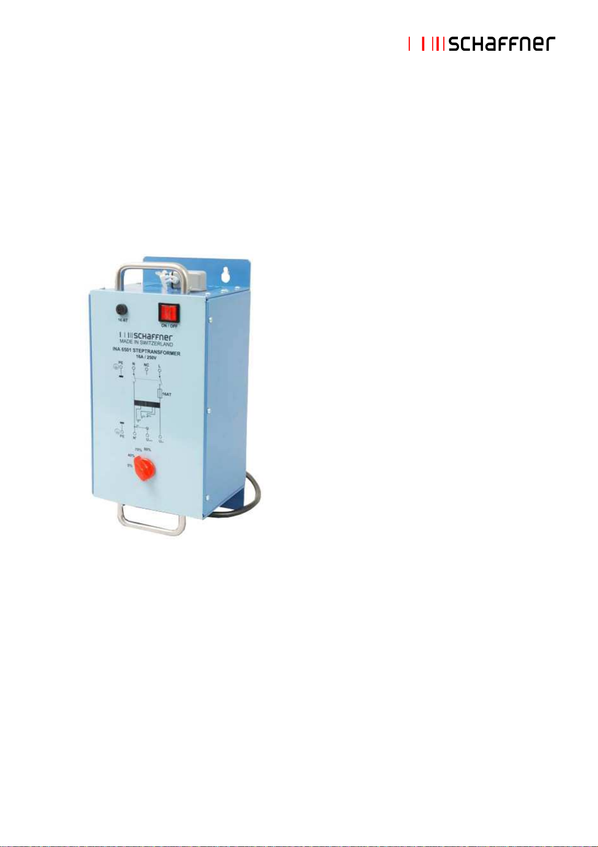
Manual step transformer INA 6501............................................................................................ 7
1.1
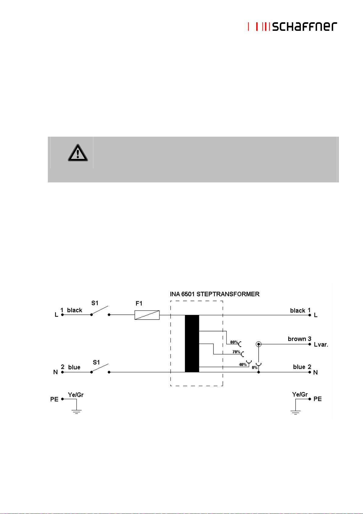
Circuit diagram INA 6501.............................................................................................................. 7
1.2
Technical specifications INA 6501................................................................................................ 8
1.2.1
Parts description ........................................................................................................................... 8
1.3
Installation - connection to Modula ............................................................................................... 8
2
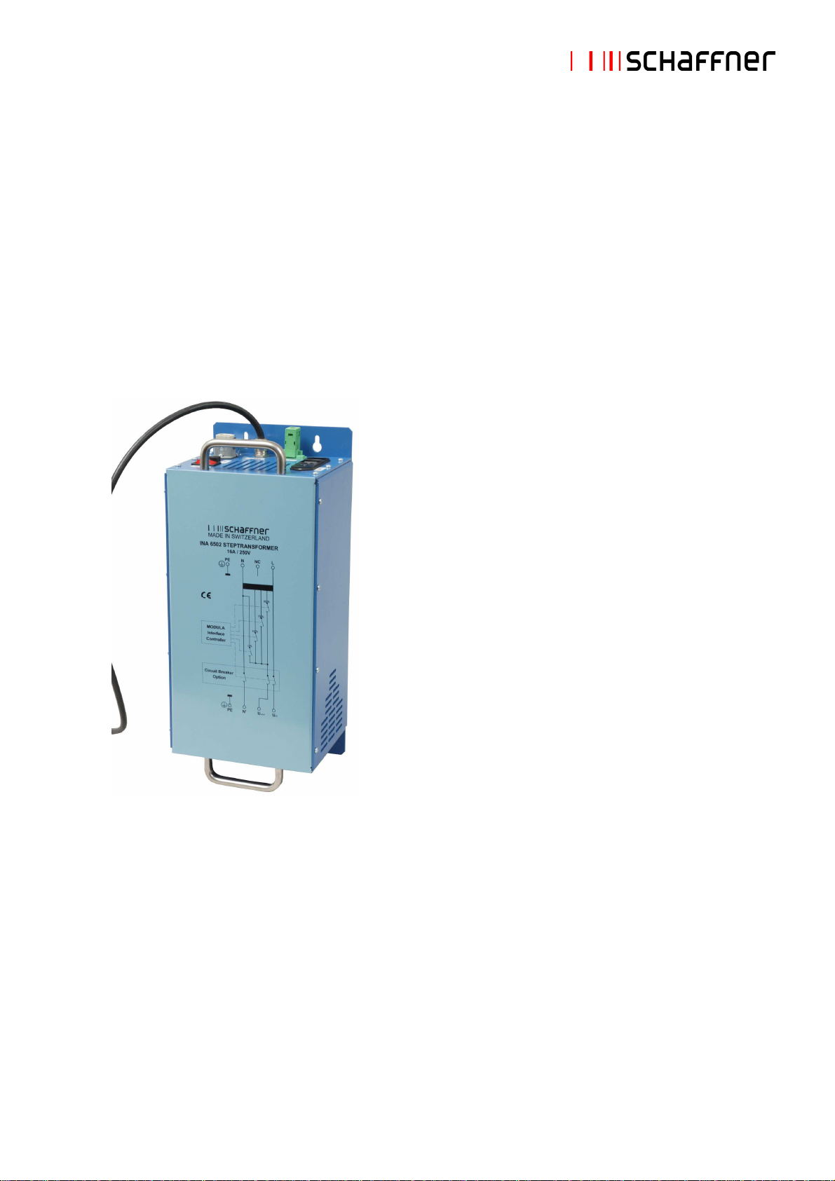
Automatic step transformer INA 6502 .................................................................................... 10
2.1
Circuit diagram INA 6502............................................................................................................ 10
2.2
Technical specifications INA 6502.............................................................................................. 11
2.2.1
Parts description ......................................................................................................................... 11
2.2.2
Compatibility ............................................................................................................................... 12
2.3
Installation - connection to Modula ............................................................................................. 13
2.4
HW Detection.............................................................................................................................. 14
2.4.1
Operation .................................................................................................................................... 14
3
Automatic variable transformer VAR 6501............................................................................. 16
3.1
Circuit diagram VAR 6501 .......................................................................................................... 16
3.2
Technical specifications VAR 6501 ............................................................................................ 17
3.2.1
Parts description ......................................................................................................................... 17
3.2.2
Compatibility ............................................................................................................................... 18
3.3
Installation - connection to Modula ............................................................................................. 18
3.4
Using WinModula standard variation test................................................................................... 19
3.5
Specials using Winmodula and variation test............................................................................. 20
3.5.1
Operation .................................................................................................................................... 20
4
Automatic variable transformer VAR 6502............................................................................. 22
4.1
Circuit diagram VAR 6502 .......................................................................................................... 22
4.2
Technical specifications VAR 6502 ............................................................................................ 23
4.3
Variable transformer VAR 6502.................................................................................................. 23
4.3.1
Parts description ......................................................................................................................... 24
4.4
Compatibility ............................................................................................................................... 24
4.4.1
Installation - connection to Modula ............................................................................................. 25
4.4.2
Operation .................................................................................................................................... 25
5
Manual variable transformer VAR 6503.................................................................................. 27
5.1
Circuit diagram VAR 6503 .......................................................................................................... 27
5.2
Technical specifications VAR 6503 ............................................................................................ 28
5.2.1
Parts description ......................................................................................................................... 28
5.3
Installation - connection to Modula ............................................................................................. 28
6
Magnetic fields options MFO 650X ......................................................................................... 30
6.1
Magnetic field loops INA 701 and INA 702................................................................................. 30
6.2
Manual magnetic field option MFO 6501.................................................................................... 32
6.2.1
Circuit diagram MFO 6501.......................................................................................................... 33
6.2.2
Technical specifications MFO 6501............................................................................................ 33
6.2.3
Parts description ......................................................................................................................... 34
6.2.4
Installation................................................................................................................................... 34
6.2.5
Operation – adjustments............................................................................................................. 35
6.3
Automatic magnetic field option MFO 6502................................................................................ 36
6.3.1
Circuit diagram MFO 6502.......................................................................................................... 37
6.3.2
Technical specifications MFO 6502............................................................................................ 37
6.3.3
Parts description ......................................................................................................................... 38
6.3.4
Compatibility ............................................................................................................................... 38
6.3.5
Installation - connection to Modula ............................................................................................. 38
6.3.6
Operation .................................................................................................................................... 39