6
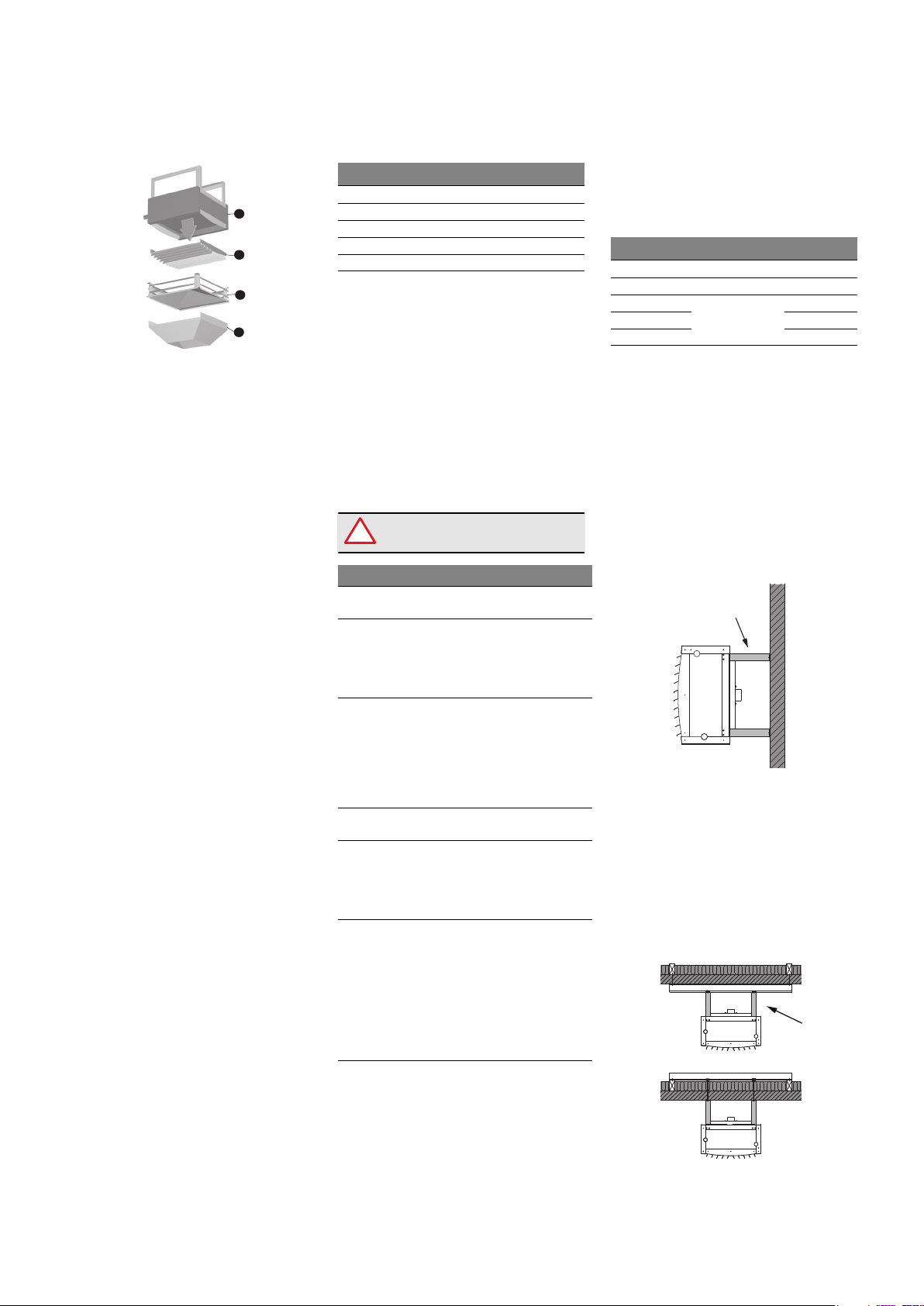
3.5 Electrical connections
The electrical connections
must be made according to
current regulations and by
authorised personnel.
Connect the motors to the electrical
supply.
The fans can be connected to
different types of speed regulators.
See the wiring diagrams on pages 10
to 13.
After connecting the motor, check
the direction of rotation from the fan
inlet side.
Directions of rotation
• VM-4 and –5: Counter-
clockwise
• VM-6, -7 and –8: Clockwise
Access to the fan motor on units with
mixing housings is typically done by
removing a side plate opposite the
damper shaft.
The damper motor has a terminal
box for direct cable connection.
4. Maintenance
The air heaters are designed to give
long and reliable operation and to
require little service.
The electric system must be
switched off and locked to
avoid unintentionally starts
when the air heaters are
undergoing maintenance.
The air heaters must be kept clean at
all times for optimum performance
and best level of comfort. Inspect
and clean the units as needed. Units
installed indust-filled environments
require more frequent maintenance.
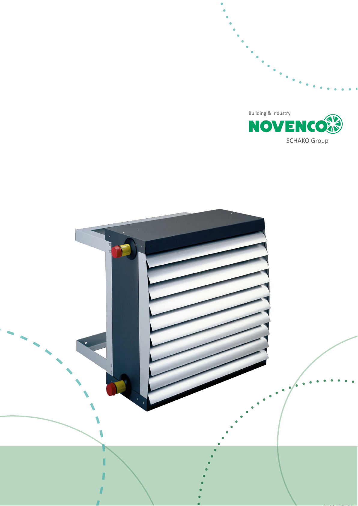
Refer to figure 1. Basic unit in the
following sections.
4.1 Inspection
Air heaters without accessories on
the inlet side can be checked directly.
Inspection of the inlet on units with
mixing housings is typically done by
removing a vertical side plate of the
mixing housing opposite to the
damper shaft.
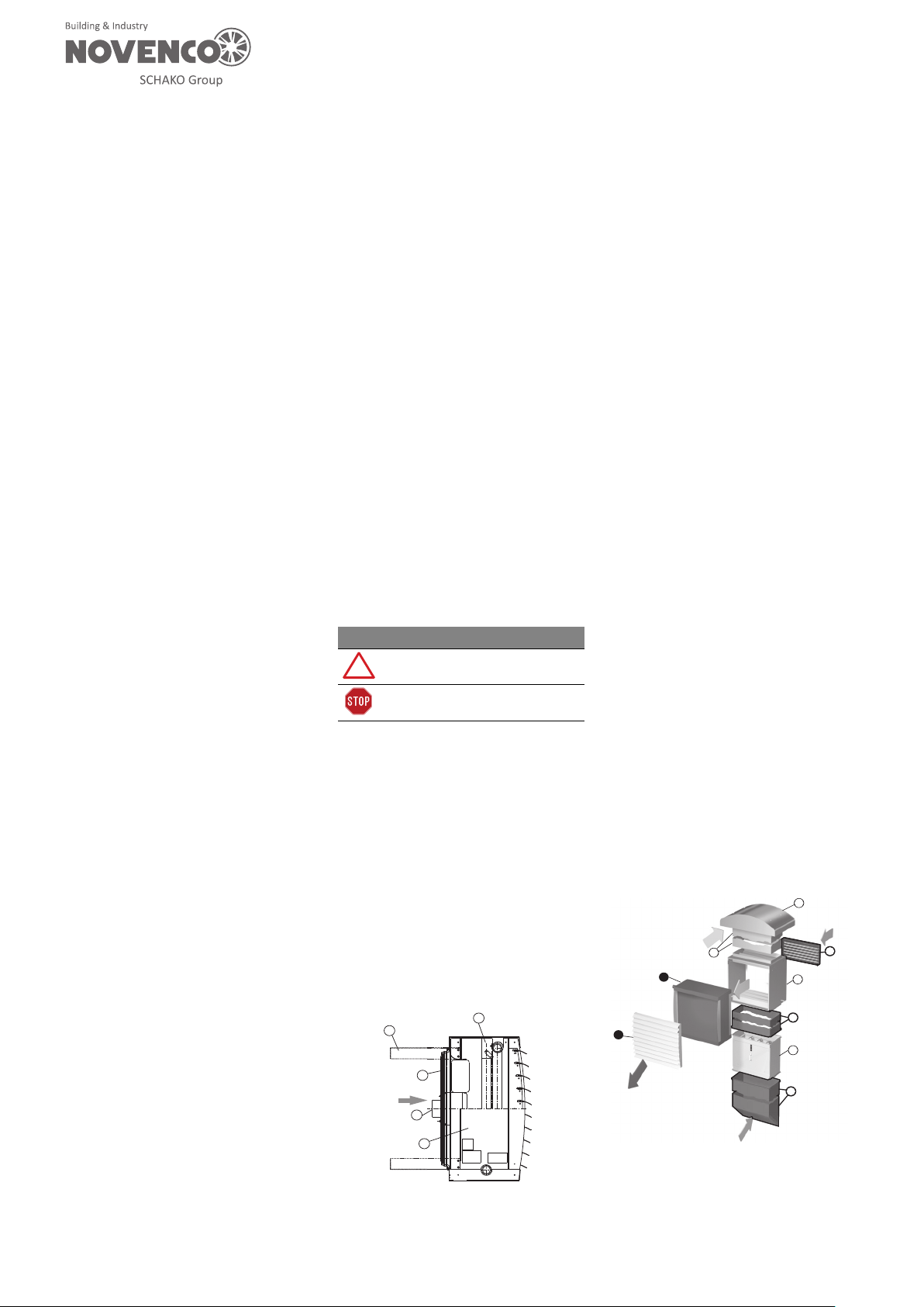
4.2 Cleaning
Dust builds up inside the unit
cabinets and reduce the
performance if not removed.
Build-ups on fan suspensions, wire
guards, heating coils and dampers
can usually be removed by vacuum
cleaning. Cleaning the inlet of the
heating coil can be done after
removing the fan unit with
suspension. See section “4.4 Motor”.
On the outlet side it is possible to
remove the front grille.
Wall grilles for fresh air and wire
guards for return air ducts must also
be kept free from dust and foreign
particles.
4.3 Impeller
Prior to delivery, the fan unit has
been carefully balanced. If
vibrations occur during operation, it
is normally due to dust on the fan
blades. If vibrations persist after
cleaning; stop the unit and call for
skilled assistance. Continued
operation may damage the motor
bearings.
4.4 Motor
The motor and impeller is a one
piece assembly. The motor bearings
are greased for life, i.e. approx.
30.000 working hours and cannot be
greased anew. When the service life
of the bearings has run out, they
should be replaced. Replacement of
the bearings should be carried out by
a specialist. During replacement,
remove the entire unit comprising
fan suspension and fan. Afterwards,
remove the suspension from the fan.
When re-mounting, the fan must be
centred carefully with equal blade
clearance around the circumference.
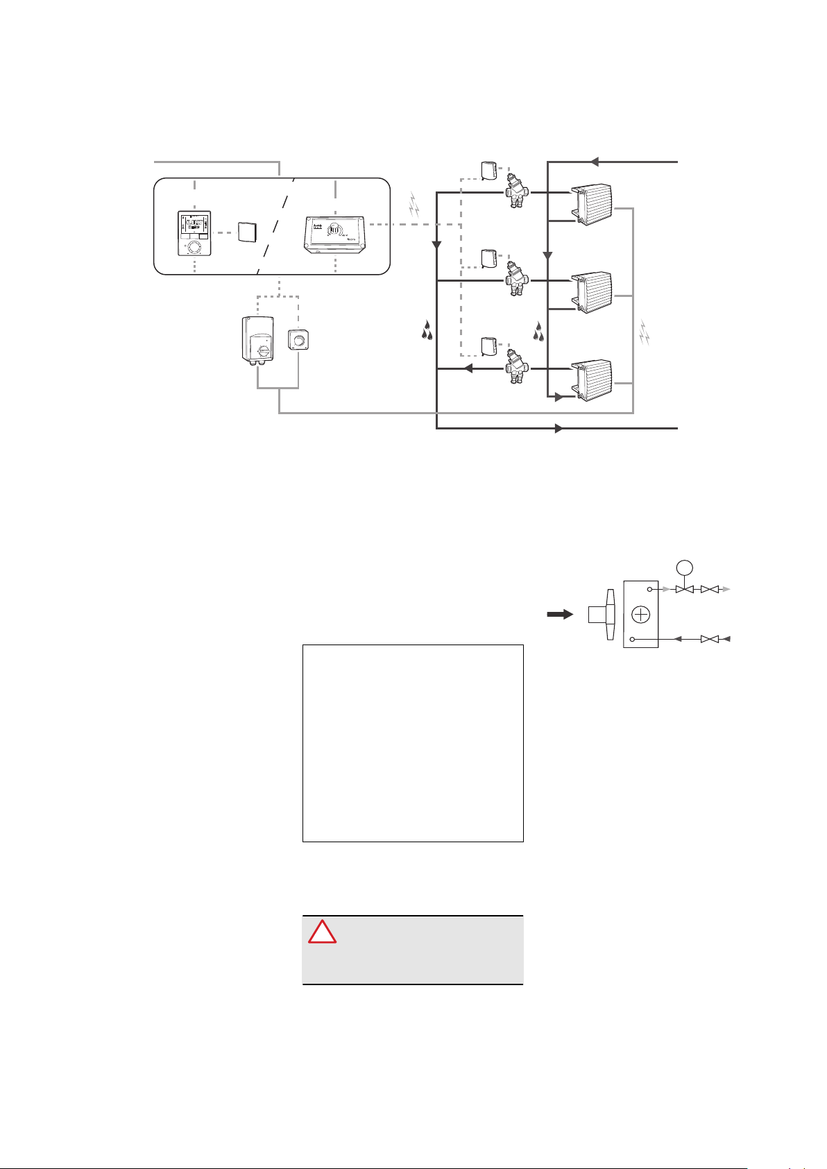
4.5 Heating coil
The heating coil has copper tubes
with aluminium fins and is sensitive
to frost. If there is a risk of hard frost,
it might be necessary – besides the
established frost protection at the
fresh air inlet – to empty the heating
coilofwater.Inexposedinstallations
it is recommended to supply the
plant with antifreeze.
4.6 Damper
The damper function should be
checked on occasion.
4.7 Filters
Filters from Novenco are made of
synthetic material and must be
cleaned occasionally to maintain fan
performance. Cleaning is done
either by vacuum cleaning the dirty
side of the filter mat, rinsing from the
clean side or by washing in
lukewarm soap water at max. 40 °C.
The filter mat can be washed four
times, before it must be replaced.
During cleaning or replacement of
the filter, draw out the filter cassette
and insert a new filter after cleaning
the mat retainers. The filter cassette
is fitted with a handle. The retainers
are of Velcro and reusable.
When ordering a new filter mat,
observe the type and size of fan, e.g.
VMA-62.
The filter condition must be checked
2 weeks after start-up of the fan and
then once every month.
Recommended rise in differential
pressure above the filter mat is
100 Pa.
4.8 Other components
Components for regulation,
ventilation, water outlet and other
accessories essential for the correct
operation of the fan, need regular
inspection and maintenance
according to the manufacturer’s
instructions.