Schenker ZEN 150 User manual

COD: 150Z24.B.2021
Installation, use and maintenance manual
ZEN 150
24 V dc

COD: 150Z24.B.2021
THE PRESENT MANUAL BELONGS TO - Schenker Italia -ALL RIGHTS RESERVED
INDEX
1. LAYOUT OF MANUAL........................................................................................................................................3
1.1 STRUCTURE OF THE MANUAL ............................................................................................................................3
1.2 DESCRIPTION OF THE SYMBOLS .......................................................................................................................3
2. GENERAL WARNINGS AND INFORMATION TO THE RECIPIENT .....................................................4
2.1 IMPORTANT INFORMATION ................................................................................................................................4
2.2 SAFETY WARNINGS ............................................................................................................................................4
2.3WARRANTY..........................................................................................................................................................5
2.4IDENTIFICATION OF THE UNIT ..........................................................................................................................6
2.5LEGISLATIVE REFERENCE ..................................................................................................................................6
2.5.1 DIRECTIVES AND STANDARDS CONCERNING MACHINE SAFETY .................................................................6
2.5.2 RESPECT FOR THE ENVIRONMENT –REQUIREMENTS FOR REMOVAL AND DISPOSAL...............................6
3. PRESENTATION OF THE PRODUCT ............................................................................................................8
3.1 TRANSPORT AND MATERIAL HANDLING ...........................................................................................................8
3.2 STOCKAGE ..........................................................................................................................................................9
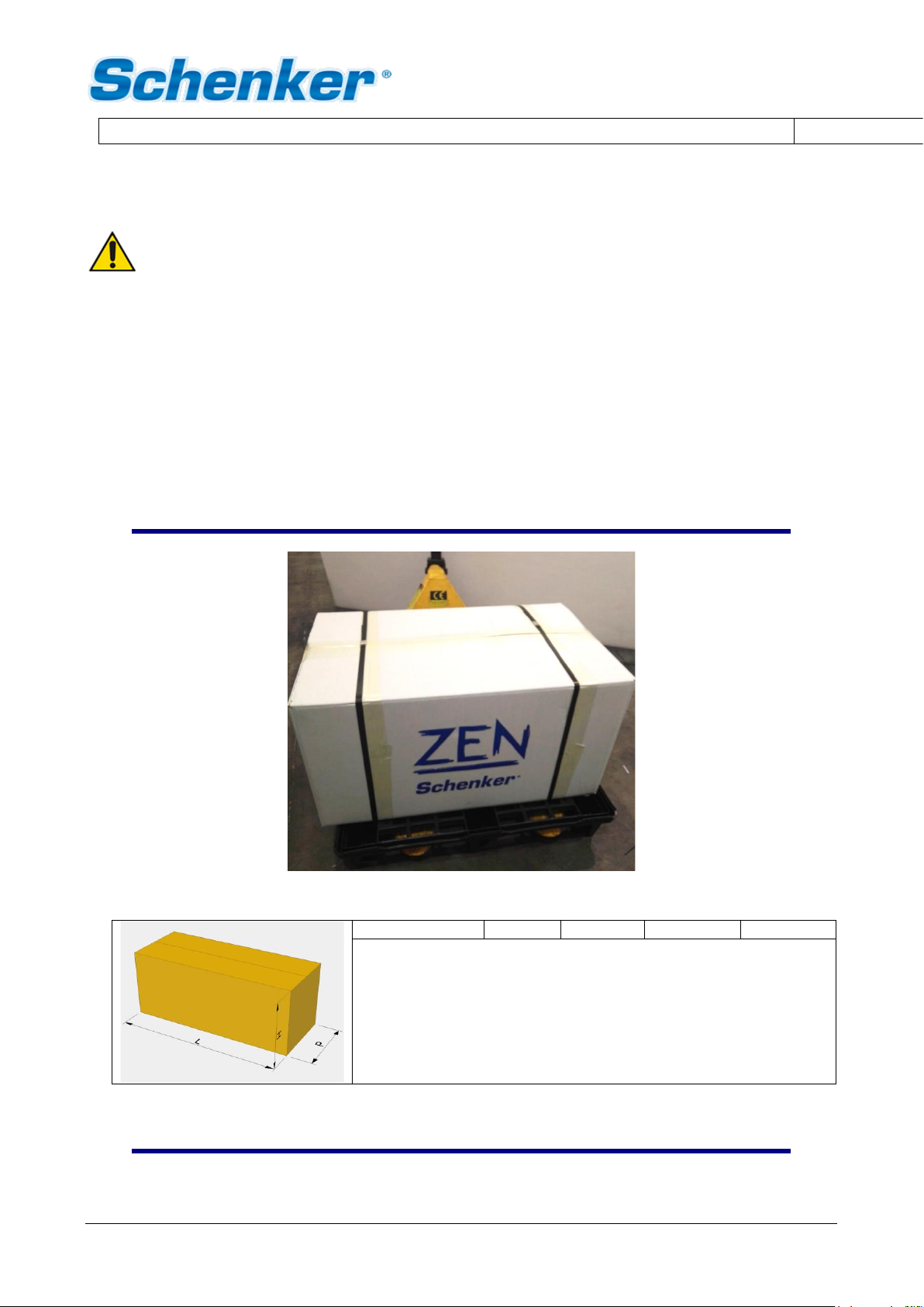
3.3 PACKAGING.........................................................................................................................................................9
3.3.1 PACKAGING CONTENTS...................................................................................................................................9
3.4 ATTACHED DOCUMENTS ..................................................................................................................................10
3.5 TECHNICAL DATA .............................................................................................................................................10
3.6 FEATURES OF THE PRODUCT ...........................................................................................................................11
3.7 ADVANTAGES OF THE ENERGY RECOVERY SYSTEM ......................................................................................12
3.8 COMPOSITION OF THE MACHINE ....................................................................................................................13
3.8.1 PUMP GROUP ..................................................................................................................................................13
3.8.2 WATERMAKER GROUP....................................................................................................................................14
3.8.3 ACCESSORIES ................................................................................................................................................16
4. INSTALLATION.................................................................................................................................................17
4.1 GENERAL CRITERIA ..........................................................................................................................................17
4.2 COMPONENTS INSTALLATION..........................................................................................................................18
4.2.1 PUMP GROUP..................................................................................................................................................18
4.2.2 WATERMAKER GROUP ...................................................................................................................................18
4.2.3 ACCESSORIES................................................................................................................................................21
4.3 INSTALLATION ..................................................................................................................................................21
4.3.1 WATER INTAKE AND DISCHARGE.................................................................................................................21
4.3.2 SEAWATER INTAKE........................................................................................................................................21
4.3.3 FRESH WATER CONNECTION FOR FLUSHING ..............................................................................................22
4.3.4 BRINE DISCHARGE ........................................................................................................................................22
4.4 HYDRAULIC CONNECTIONS .............................................................................................................................23
4.5 ELECTRIC CONNECTIONS.................................................................................................................................26
4.5.1 REMOTE CONTROL PANEL INSTALLATION ...................................................................................................26
4.5.2 ELECTRIC CONNECTIONS:WIRES (ZEN 150 12/24V DC)...................................................................26
5. FUNCTIONING AND USE..............................................................................................................................28
5.1 COMMAND DESCRIPTION..................................................................................................................................28
5.1.1 ALARMS DESCRIPTION ..................................................................................................................................28
5.2FIRST START UP PROCEDURE ..........................................................................................................................28
5.2.1 PRELIMINARY CHECKS BEFORE PROCEEDING WITH THE START-UP PROCEDURE ...................................29
5.2.2 START-UP.......................................................................................................................................................29
5.3NORMAL OPERATING PROCEDURE ..................................................................................................................30

COD: 150Z24.B.2021
THE PRESENT MANUAL BELONGS TO - Schenker Italia -ALL RIGHTS RESERVED
5.3.1 NORMAL OPERATING PROCEDURE WITHOUT FINAL FLUSHING .................................................................30
5.3.2 NORMAL OPERATING PROCEDURE WITH FINAL FLUSHING (RECOMMENDED PROCEDURE)...................30
5.3.3 WORKING CYCLE WITH TIMER .....................................................................................................................31
5.3.4 LONG FLUSHING PROCEDURE.......................................................................................................................31
5.4RESET PROCEDURE .......................................................................................................................................31
6. MAINTENANCE (ROUTINE AND SPECIAL).............................................................................................34
6.1 CHECK FILTER CLEANLINESS ..........................................................................................................................34
6.2 CHECK THE WATERMAKER WORKING PRESSURE...........................................................................................35
6.3 CHECK FOR LEAKS............................................................................................................................................35
6.4 CHECK FOR MEMBRANES REPLACEMENT ........................................................................................................35
6.5 SHUTDOWN PROCEDURE .................................................................................................................................35
6.5.1 NECESSARY EQUIPMENT ..............................................................................................................................36
6.5.2 SHUTDOWN OPERATING PROCEDURE..........................................................................................................37
6.6 ANTIFREEZE PROCEDURE (WINTERIZING PROCEDURE IN COLD CLIMATE -UNDER 5°C).......................39
6.7 PERIODIC MAINTENANCE.................................................................................................................................40
6.7.1 MEMBRANE REPLACEMENT............................................................................................................................40
6.8 ADJUSTMENTS ..................................................................................................................................................40
7. TROUBLESHOOTING......................................................................................................................................41
7.1 TROUBLESHOOTING CHART.............................................................................................................................41
8. SUGGESTED SPARE PARTS.........................................................................................................................42
8.1 SHORT TERM CRUISING...................................................................................................................................42
8.2 LONG TERM CRUISING .....................................................................................................................................42

1 –LAYOUT OF MANUAL COD: 150Z24.B.2021
EN
THE PRESENT MANUAL BELONGS TO - Schenker Italia -ALL RIGHTS RESERVED
3
1. LAYOUT OF MANUAL
1.1 Structure of the manual
The manual is divided into chapters, which gather all the information necessary to use the system without
risks.
In each chapter there is a subdivision in paragraphs to focus on essential points; each paragraph can be found
with a subtitle and a description.
Within the chapter, for example chapter 1, we will have:
1 Chapter title
1.1 Paragraph title
1.1.1 Subtitle
1.1.1.1 Further subtitles
The numbering of the figures and tables, is reset to each chapter; therefore, we will find the prefix indicating
the chapter and the page number, figure or table in progressive that starts from number 1 at the beginning of
each chapter.
1.2 Description of the symbols
The following symbols will be used in the manual to highlight important indications and warnings:
ATTENTION:
This symbol indicates accident prevention regulations for the operator and / or for any exposed
persons.
CAUTION:
This symbol indicates that there is the possibility of damaging the system and / or its components.
NOTE:
This symbol indicates useful information.

2 - GENERAL WARNINGS & INFORMATION TO THE RECIPIENT COD: 150Z24.B.2021
EN
THE PRESENT MANUAL BELONGS TO - Schenker Italia -ALL RIGHTS RESERVED
4
2. GENERAL WARNINGS AND INFORMATION TO THE RECIPIENT
2.1 Important information
In order to safeguard the operator's safety and avoid possible damages to the machine, before carrying out
any operation on the machine, it is essential to read carefully all the instructions.
This manual must be left complete and legible in its entirety, every operator involved in the use of the machine,
or responsible for maintenance or adjustment operations, must know its location and must have the possibility
to consult it any time.
All rights of reproduction of this manual are reserved to SCHENKER ITALIA. This manual cannot be transferred
to third parties without the written authorization of SCHENKER ITALIA.
The text cannot be used in other documents without the written permission of SCHENKER ITALIA.
The descriptions and illustrations provided in this publication are not binding.
SCHENKER ITALIA reserves the right to make any modifications considered appropriate.
© SCHENKER ITALIA
THIS MANUAL IS PROPERTY OF SCHENKER ITALIA, ANY REPRODUCTION, EVEN PARTIAL, IS
PROHIBITED.
This manual was drafted according to the requirements of the 2006/42 / EC Machinery Directive.
2.2 Safety warnings
•Wear protective equipment suitable for service operation.
•Do not remove safety devices or accident prevention protection.
•Check if the system is properly installed contacting a Schenker service point.
•Verify that the electric and hydraulic connections follow the indicated specifications.
•Avoid using the watermaker if the sea water is polluted.
•Children and inexperienced people shall not touch or use the system.
•Check periodically that no leaks are present. Avoid installing the system where a leak may cause damage
and/or jeopardize the safety of the vessel.
•Maintenance should only be carried out by qualified people or Schenker technicians.

2 - GENERAL WARNINGS & INFORMATION TO THE RECIPIENT COD: 150Z24.B.2021
EN
THE PRESENT MANUAL BELONGS TO - Schenker Italia -ALL RIGHTS RESERVED
5
ATTENTION
Any technical changes or operating conditions indicated which affect the correct operation or
safety of the machine must only be carried out by the manufacturer's technical staff or by
technicians formally authorized by the manufacturer. Otherwise, SCHENKER ITALIA declines
any responsibility for changes or damages that may result from it.
2.3 Warranty
The equipment and the relevant accessories are under 12-month warranty from delivery date. The warranty
does not include consumable items (filters, carbon filters, membranes, etc.). The “ERS” pressure amplification
device is under 36-month warranty, as long as the watermaker is given a proper maintenance by a specialized
Schenker technician. The warranty covers faults due to defected materials and parts. It is limited to the
replacement or repair of faulty parts. The charge for the disconnecting and reinstalling on the vessel, as well
as the transport from or to our Service Point (or our factory) shall be at the customers own expenses.
The under warranty delivered parts transport shall be at customer’s own risk.
In case of repairs under warranty performed by our technicians on the customer’s vessel, the faulty parts
replacement cost shall be at Schenker's expense, while manpower and travel expenses will be charged on the
customer. The warranty does not include faults caused by negligence in operating, maintenance and
installation of the device (if not carried out by an authorised Schenker Service point).
Dismantling by non-authorized personnel will invalidate the warranty. Schenker Italia will not be responsible
for any direct or indirect damage caused by the malfunctioning equipment, limiting its liability to the repair and
replacement of faulty parts.
ATTENTION
SCHENKER ITALIA declines any responsibility for improper use of the machine, for damages
caused as a result of operations not covered by this manual or unreasonable use.

2 - GENERAL WARNINGS & INFORMATION TO THE RECIPIENT COD: 150Z24.B.2021
EN
THE PRESENT MANUAL BELONGS TO - Schenker Italia -ALL RIGHTS RESERVED
6
2.4 Identification of the unit
The Zen Watermaker can be identified by a serial number printed on the top valve of the unit.
Serial number
Fig. 2-1
2.5 Legislative reference
2.5.1 Directives and standards concerning machine safety
•Machinery Directive 2006/42 / EC, in force since December 29, 2009;
•Low Voltage Directive 73/23 / EEC and subsequent amendments and additions: 93/68 / CEE
implemented by the Law of 18 October 1997 n. 791.
•Electromagnetic Compatibility Directive 89/336 / EEC and subsequent amendments and additions:
93/31 / CEE implemented with D.L. December 4, 1992 n. 476.
•Standards UNI EN 292/1 and 292/2 (safety of machinery);
2.5.2 Respect for the environment –requirements for removal and disposal
ATTENTION
Removal and disposal of materials, as result of the decommissioning of the machine, must be
performed in accordance with the regulations in force, for the safeguard and protection of the
environment.
According to removal and disposal, it should be highlighted that the construction materials of the machine are
not dangerous for the environment and consist essentially of:
- Stainless Steel;
- Plastic;
- Carbon fibre;
- Motors, cables and consumable electrical materials;
- Rubber and polyurethane seals.

2 - GENERAL WARNINGS & INFORMATION TO THE RECIPIENT COD: 150Z24.B.2021
EN
THE PRESENT MANUAL BELONGS TO - Schenker Italia -ALL RIGHTS RESERVED
7
The various materials must be discarded according to the regulations of the country where the machine has
been uninstalled.
The machine does not contain dangerous components or substances that require special removal procedures.
ATTENTION
Different legislations are in force in the different countries, therefore the prescriptions imposed
by the laws and by the agencies designated by the Countries must be observed.

3 –PRESENTATION OF THE PRODUCT COD.30Z12/24.B.2021
3 –PRODUCT PRESENTATION COD: 150Z24.B.2021
THE PRESENT MANUAL BELONGS TO - Schenker Italia -ALL RIGHTS RESERVED
8
3. PRESENTATION OF THE PRODUCT
ATTENTION
Be sure to follow general safety instructions.
•Wear protective equipment suitable for the transport and handling operations.
•Lift the machine with equipment appropriate to the weight and size of the box, taking the utmost care
and following carefully the instructions on the present use and maintenance manual (attachment points
for loading devices, etc.).
•Make sure that the lifting equipment used is in good condition and properly maintained.
•Do not stand under the package during lifting or transport operations.
3.1 Transport and material handling
The watermaker unit is transported in a cardboard box. Dimensions and weight are indicated in the following
table.
MATERIALS HANDLING
fig. 3-1
Packaging dimensions and weight
tab.3-1
Model
L cm.
W cm.
H cm.
Weight Kg.
Zen 150
87
64
55
80

3 –PRESENTATION OF THE PRODUCT COD.30Z12/24.B.2021
3 –PRODUCT PRESENTATION COD: 150Z24.B.2021
THE PRESENT MANUAL BELONGS TO - Schenker Italia -ALL RIGHTS RESERVED
9
3.2 Stockage
ATTENTION
To avoid damage to the system, be sure to keep the unit in a dry place with a temperature
between 5°C and 45°C. Very cold temperatures could led to a freezing of the fluid inside the
system and, as a clear consequence, a permanent damage of the latter.
3.3 Packaging
3.3.1 Packaging contents
PACKAGING (picture for purely information)
FIG. 3-2
ZEN 150
Watermaker
Pump group
Active carbon filter with electrovalve
5 microns filter with accumulator
Mesh filter
Non-return valve with Tee fitting
Remote panel
10 mt extension cable for remote panel
Installation kit
Filter key
6x8 hose for production

3 –PRESENTATION OF THE PRODUCT COD.30Z12/24.B.2021
3 –PRODUCT PRESENTATION COD: 150Z24.B.2021
THE PRESENT MANUAL BELONGS TO - Schenker Italia -ALL RIGHTS RESERVED
10
3.4 Attached documents
The package contains the technical documentation (use and maintenance manual, electric and hydraulic
scheme, warnings and instructions).
ATTENTION
•Read carefully the use and maintenance
manual before installing the system.
•Use only recommended material for the
installation (especially hoses, fittings and
seals) in accordance with the manual.
•Do not store the unit under temperature
below 5°C and above 45 °C
DOCUMENTS INCLUDED IN THE PACKAGING (picture for purely information)
FIG. 3-3
3.5 Technical data
WATERMAKER
WATERMAKER DIMENSIONS
FIG. 3-4

3 –PRESENTATION OF THE PRODUCT COD.30Z12/24.B.2021
3 –PRODUCT PRESENTATION COD: 150Z24.B.2021
THE PRESENT MANUAL BELONGS TO - Schenker Italia -ALL RIGHTS RESERVED
11
Weight 46,1 Kg (empty)
Hydraulic Connection
Seawater inlet: hose barb for 20mm internal diameter reinforced hose.
Brine Discharge: hose barb for 16mm internal diameter reinforced hose.
Fresh water: ¼’’ fitting, 6x8mm hose.
PUMP
Dimensions
Length: 42 cm
Width: 15 cm
Height: 23 cm
Weight: 14,3 Kg
Hydraulic Connection
Water inlet: hose barb for 20mm internal diameter reinforced hose.
Water outlet: hose barb for 16mm internal diameter reinforced hose.
Feed pump type: Rotative pump
Filters: n. 1 Cartridge filter 5 microns 2.32" x 9 ¾’’
n. 1 Active carbon filter 2.32" x 9 ¾’’
Power supply: 24 VDC +/- 15% (150Z24 version)
Average electric consumption: 600 Wh average
Nominal fresh water production: 150 Lit/h +/- 20% @ seawater 25 °C salinity 35.000 ppm
CEE conformity: In compliance with directives 89/392 CEE sect.1 (general safety machines
requirements), 89/336 CEE (electromagnetic compatibility), 73/23 CEE
(electric safety requirements)
3.6 Features of the product
The fresh water produced by a Schenker watermaker, obtained by clean seawater, has a high purity. Despite
this, the potability may not be guaranteed: bacterium caused by non-observance of shutdown and cleaning
procedures may be present in the watermaker. Therefore, it is essential that the correct shut down and storage
procedures are followed to ensure continued purity of the fresh water. UV treatment of the fresh water may
well be beneficial.

3 –PRESENTATION OF THE PRODUCT COD.30Z12/24.B.2021
3 –PRODUCT PRESENTATION COD: 150Z24.B.2021
THE PRESENT MANUAL BELONGS TO - Schenker Italia -ALL RIGHTS RESERVED
12
3.7 Advantages of the Energy recovery system
Introduction
Thank you for choosing a Schenker Watermaker.
The knowledge of operating and maintenance procedures allows to use the system in the best way, and to
guarantee a perfect functioning throughout the years. We invite you to read carefully this manual and to keep
it for a quick reference.
Functioning principles
The Schenker watermakers, as an alternative to the high-pressure pumps of traditional systems, use the
ENERGY RECOVERY SYSTEM patented device, which amplifies the pressure of common low-pressure
pumps, and recover all the hydraulic energy back from the membranes, allowing a high energy efficiency.
The lack of high-pressure pumps makes the system silent and vibration-free and enormously simplifies its use
since no adjustment is necessary for its operating.
FUNCTIONING SCHEME
FIG. 3-5

3 –PRESENTATION OF THE PRODUCT COD.30Z12/24.B.2021
3 –PRODUCT PRESENTATION COD: 150Z24.B.2021
THE PRESENT MANUAL BELONGS TO - Schenker Italia -ALL RIGHTS RESERVED
13
3.8 Composition of the machine
The machine is composed of the following parts:
1. PUMP GROUP
2. WATERMAKER GROUP
3.8.1 Pump group
This pump draws sea water and sends it to the watermaker group, through the pre-filter.
The pump group is composed of the following components:
•5 micron cartridge filter
•Pressure transducer
•Pump box
•Accumulator
PUMP GROUP
FIG. 3-6
5 micron filter + accumulator
Pump head + motor
Pressure transducer
Pump box
Pressure transducer. It Is hydraulically connected to the pump group. It stops the system if the pump pressure
exceeds 14 bar or if it doesn’t reach 1,3 bar.
Pump box. Plastic Box with all the electric connections for the power supply of motor, motherboard, pressure
transducer, remote panel and electrovalve.
Accumulator. This is a polypropylene air reservoir. Its function is to reduce and stabilize the pressure peaks
during the watermaker functioning. The device has to be pre-charged with air through the Schrader valve. The
pressure is about 6 Bar. The accumulator is preloaded in factory to the correct pressure.

3 –PRESENTATION OF THE PRODUCT COD.30Z12/24.B.2021
3 –PRODUCT PRESENTATION COD: 150Z24.B.2021
THE PRESENT MANUAL BELONGS TO - Schenker Italia -ALL RIGHTS RESERVED
14
3.8.2 Watermaker group
WATERMAKER GROUP (SIDE VIEW W/O COVER)
FIG. 3-7
Watermaker outlet/discharge
Watermaker inlet
Reverse osmosis membranes
Fresh water production
WATERMAKER GROUP (FRONT VIEW W/O COVER)
FIG. 3-8
Reset valve
Manometer
Depressurization valve
Positioner knob

3 –PRESENTATION OF THE PRODUCT COD.30Z12/24.B.2021
3 –PRODUCT PRESENTATION COD: 150Z24.B.2021
THE PRESENT MANUAL BELONGS TO - Schenker Italia -ALL RIGHTS RESERVED
15
The watermaker group is composed of the following parts:
•Reverse osmosis membranes
•Energy Recovery System
•Manometer
•Depressurization valve
•Positioner
•Reset valve
Reverse osmosis membranes. They are installed inside the carbon fibre high-pressure housing. Membranes
are n.2 x SW4021 type. Their purpose is to separate the intake high-pressure seawater in two flows: one for
the salt-water drain and one for the fresh water production.
Energy Recovery System. The heart of the system. It has the function of amplifying the pressure supplied by
the pumps and to recoup the hydraulic energy back from the membranes. The ERS device makes periodic
cycling by a hydraulically controlled automatic valve. The cycles are noticeable through a ”beat” issued by the
watermaker unit. The unit is based on cylinders and a central body containing the hydraulic valve necessary
for the system to function.
Manometer. Located on the right side of the watermaker, it measures the working pressure of the watermaker.
Depressurization valve. It is used for the air bleeding of the unit. It is located on the top of the watermaker.
Its function is to depressurize the system and to allow the bleeding of air. The valve must be closed during
normal working conditions (completely screwed in) and it is opened during the air bleeding operations (slightly
unscrewed).
Positioner. It is a stainless steel threaded arm, with a black knob, located on the right hand side of the
watermaker. Its function is to reset the unit in case of hydraulic block.
Reset valve. It is installed on top of the ERS it is recognizable by the little blue lever. The valve must be closed
during normal functioning (lever perpendicular to the valve). This valve has the function ofallowing the resetting
of the ERS in case of a system block. It must be opened before screwing in the valve positioner.

3 –PRESENTATION OF THE PRODUCT COD.30Z12/24.B.2021
3 –PRODUCT PRESENTATION COD: 150Z24.B.2021
THE PRESENT MANUAL BELONGS TO - Schenker Italia -ALL RIGHTS RESERVED
16
3.8.3 Accessories
The main accessories of the watermaker are the following:
•Active carbon filter
•Electrovalve (or solenoid valve)
•Non-return valve (or check valve)
•Mesh filter (strainer)
ACCESSORIES
FIG. 3-9
Non-return valve
Active carbon filter
Mesh filter (strainer)
Electrovalve
Active carbon filter. This filter is connected between the fresh water pressurized system of the boat and the
electro valve on the filter holder. A manual valve positioned on the filter inlet allows replacement of the cartridge
without depressurizing the fresh water system of the vessel.
Electrovalve (or solenoid valve). It has the function of switching from seawater intake to fresh water tank
when washing the watermaker.
Non-return valve (or check valve). It stops water flowing out of the inlet hose. It must be installed vertically.
It stops leaking of fresh water from the seacock while the washing procedure starts.
Mesh filter. The machine is equipped with a strainer to protect the pump from macro sediments. This is placed
between the seacock and the pump.

4 –INSTALLATION COD: 150Z24.B.2021
EN
THE PRESENT MANUAL BELONGS TO - Schenker Italia -ALL RIGHTS RESERVED
17
4. MOUNTING AND INSTALLATION
4.1 General criteria
Before starting the installation, it is important to carefully plan all the activities, by evaluating all the siting
locations of the equipment. The main points to focus on are the followings:
•Selecting of seawater inlet/outlet
•Positioning of the main units (pump group, watermaker group, active carbon filter).
•Positioning of the thermal-magnetic circuit breaker.
•Routing of the hoses and electric cables.
CAUTION
For a correct installation of the watermaker please follow the instructions below:
•The through-hull fitting should be located in a central and low position on the hull, so that air
can’t be drawn into the pump and subsequently into the watermaker itself.
•The non-return valve has to be installed under seawater level and as close as possible to the
through-hull fitting, in vertical position.
•The pump must be installed as low as possible in respect of the waterline and as close as
possible to the seawater intake (through-hull fitting). No more that 2m away unless a positive
feed is achieved by locating the pump below the waterline.
•The watermaker unit must be positioned and arranged on an adequate support which is able
to sustain the weight (about 60 kg). The max permitted room temperature must not exceed
40°C.
CAUTION
The pump group must be installed in a ventilated place, in order to facilitate the cooling of the
electric motor.
ATTENTION
The external surface of motor of the pump can reach high temperatures; therefore, it is
recommended to avoid possible contacts with inflammable liquids and materials.
NOTE
Once an installation plan has been made, it is recommended to make a schematic drawing of
the hydraulic and electric connections and attach them to the manual for future reference.

4 –INSTALLATION COD: 150Z24.B.2021
EN
THE PRESENT MANUAL BELONGS TO - Schenker Italia -ALL RIGHTS RESERVED
18
4.2 Components installation
4.2.1 Pump group
The pump group must be installed as close as possible to the waterline as (maximum no more than 600mm
above) and as close as possible to the water inlet (2m max). Therefore, it is very important to avoid starting
the system if the intake valve is closed or if inlet filters are clogged.
The pump group should be installed in a ventilated area, with the purpose of aiding the cooling of the motor.
The max allowed room temperature must not exceed 40°C.
Avoid the contact or the proximity with inflammable material or liquid, since the motor surfaces can reach
elevated temperatures. Avoid locating the pump wherever a possible loss of water can involve damages or
jeopardize its safety. The pump group must be installed on a base sufficiently horizontal, suitable to sustain
the weight of the group. The pump group is normally fixed on the support structure by passing bolts.
4.2.2 Watermaker group
Install the watermaker above the pump. The max permitted room temperature must not exceed 40°C. It
can be placed either horizontally or vertically. The watermaker must lie completely on a flat surface. The
supplied rubber-based adhesive must absolutely be stuck to the supporting surface. Once in place on
the supporting surface, the watermaker must be fastened with the provided L-brackets. In no way must the
watermaker be suspended using solely the L-brackets but it must rest on a flat surface at all times.
Otherwise a shelf is necessary as base to support the weight of the watermaker.
VERTICAL AND HORIZONTAL FIXING
FIG. 4-1

4 –INSTALLATION COD: 150Z24.B.2021
EN
THE PRESENT MANUAL BELONGS TO - Schenker Italia -ALL RIGHTS RESERVED
19
MOUNTING PROCEDURE
FIG. 4-2
POSSIBLE CONFIGURATIONS
FIG. 4-3
For a complete installation, antivibration rubber stickers are provided.
ok
ok
NO
NO
Other manuals for ZEN 150
1
This manual suits for next models
1
Table of contents
Other Schenker Boating Equipment manuals
Popular Boating Equipment manuals by other brands

SeaView
SeaView LTBU1A7800 installation instructions

Johnson Outdoors
Johnson Outdoors MINN KOTA MKA-50 quick start guide

Columbia Boat Alarms
Columbia Boat Alarms 411 installation manual

NUCANOE
NUCANOE 2520 Assembly/installation instructions

Thule
Thule HULL-A-PORT 835XTR instruction manual

Muir
Muir HR1600 Cougar user manual